EP0078854A1 - Speed detecting device - Google Patents
Speed detecting device Download PDFInfo
- Publication number
- EP0078854A1 EP0078854A1 EP82901439A EP82901439A EP0078854A1 EP 0078854 A1 EP0078854 A1 EP 0078854A1 EP 82901439 A EP82901439 A EP 82901439A EP 82901439 A EP82901439 A EP 82901439A EP 0078854 A1 EP0078854 A1 EP 0078854A1
- Authority
- EP
- European Patent Office
- Prior art keywords
- speed
- pulses
- motor
- counter
- position sensor
- Prior art date
- Legal status (The legal status is an assumption and is not a legal conclusion. Google has not performed a legal analysis and makes no representation as to the accuracy of the status listed.)
- Withdrawn
Links
Images

Classifications
-
- G—PHYSICS
- G01—MEASURING; TESTING
- G01P—MEASURING LINEAR OR ANGULAR SPEED, ACCELERATION, DECELERATION, OR SHOCK; INDICATING PRESENCE, ABSENCE, OR DIRECTION, OF MOVEMENT
- G01P3/00—Measuring linear or angular speed; Measuring differences of linear or angular speeds
- G01P3/42—Devices characterised by the use of electric or magnetic means
- G01P3/44—Devices characterised by the use of electric or magnetic means for measuring angular speed
- G01P3/48—Devices characterised by the use of electric or magnetic means for measuring angular speed by measuring frequency of generated current or voltage
- G01P3/481—Devices characterised by the use of electric or magnetic means for measuring angular speed by measuring frequency of generated current or voltage of pulse signals
- G01P3/489—Digital circuits therefor
Definitions
- the present invention relates to a speed detecting apparatus and, more particularly, to a speed detecting apparatus capable of detecting speeds with great/ accuracy during low speed operation.
- two-phase signals which are x /2 out of phase with each other and which have a frequency f proportional to the rotational speed of a motor are generated by a pulse coder. These two-phase signals are then converted into signals of a frequency 4f via a quadru- pling circuit. Finally, a frequency-to-voltage converter, for generating a voltage proportional to the frequency 4f, produces a voltage output (actual speed voltage TSA) that is proportional to the rotational. speed.
- TSA actual speed voltage
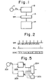
- Fig. 1 is an explanatory view of an example of the prior art, in which pulses generated by a pulse coder are counted for a predetermined period of time and applied to a microcomputer. According to this method, a pulse coder 11 is provided for generating a pulse each time a motor rotates by a predetermined amount.
- the pulses are counted by a counter 12 the content'whereof is transferred to a register 13 regularly at predetermined times, the counter being reset simultaneously therewith. Thenceforth the content of the register is read as the actual speed by a microcomputer 14. The foregoing operation is repeated thereafter to read the actual speed in digital fashion. While this method enables speed to be sensed with good accuracy when the motor is rotating at high speed, this is not the case at low motor speeds because the period of the pulses generated by the pulse coder becomes too large at such time. To improve resolution at low speed, the number of pulses generated by the pulse coder per revolution must be increased, or the reading period must be lengthened.
- SPi denotes the sampling pulses
- Pc the pulses produced by the pulse coder 11, and (CN1 the value of the count in counter 12.
- the speed data input to the microcomputer is the intermittent data 1,0,0,0,0,0. This makes it impossible to achieve accurate control of speed with a quick response.
- the object of the present invention is to provide a novel speed detecting apparatus which enables motor speed prevailing during low-speed operation to be detected with great accuracy in the form of a digital quantity without any deleterious effect upon motor response.
- Another object of the present invention is to provide a speed detecting apparatus capable of detecting the rotational speed of a motor with great accuracy from very low to high speeds.
- the present invention discloses a speed detecting apparatus having a position sensor for generating pulses the number whereof is proportional to the amount of rotation of a motor or the amount of movement of a movable machine element, the speed of the motor or of the movable machine element being detected by using the pulses generated by the position sensor.
- the speed sensing apparatus is provided with a counter which counts clock pulses for timing the period of the pulses generated by the position sensor, a register in which the content of the counter is set in synchronism with the pulses generated by the position sensor, and dividing means for performing binary or decimal division, wherein an arithmetic dividing operation is performed by the dividing means using the period stored in the register to detect the speed of the motor or movable machine element.
- the speed of the motor or movable machine element during low speed operation can be detected with great accuracy as a digital quantity. Furthermore, speed detection with great accuracy from low to high speeds is capable of being achieved by switching, in accordance with the speed of the motor or of the movable machine element, between a method of detecting speed based on counting the number of pulses generated by the position sensor, and a method of detecting speed based on timing the period of the pulses.
- Fig. 1 is a block diagram of a conventional speed detecting circuit
- Fig. 2 is an explanatory view for describing the defect of the conventional system
- Fig. 3 is a block diagram of a speed detecting circuit according to the present invention
- Fig. 4 is a waveform diagram of signal indicative of speed detected according to the present invention
- Fig. 5 is a block diagram of another embodiment according to the present invention.
- Fig. 3 is a block diagram illustrating an embodiment of the present invention
- numeral 101 denotes a pulse coder for producing two pulsed signals Pc, Pc' displaced in phase from each other by ⁇ /2, the pulses in each signal being generated whenever a motor, not shown, rotates by a predetermined amount.
- Numeral 102 denotes a rotational direction discriminating circuit for producing a rotational direction signal SGN upon sensing which of the pulsed signals Pc, Pc' leads in phase.
- Numeral 103 denotes a counter having a clear terminal CLR, a count enable terminal EN, a clock terminal CLK, and a carry pulse generating terminal TC. The pulsed signal Pc is applied to the clear terminal CLR, and logical "1" is constantly applied to the count enable terminal EN.
- the counter 103 consequently is cleared of its data each time a pulse Pc is generated, and counts up the clock pulses CP until the generation of the next pulse Pc.
- a flip-flop 104 is set each time a carry pulse OFP is generated, and is reset each time a pulse Pc is generated.
- the number of clock pulses generated in one period of the pulsed signal Pc is indicated by the counter 103 and flip-flop 104. It should be noted that the flip-flop 104 can be dispensed with if the counter 103 has a sufficiently large capacity.
- Numeral 105 denotes an AND gate, and 106 an n-bit register in which the value of the count in counter 103 is set whenever the output of AND gate 105 goes to logical "1", that is, whenever the pulse Pc is generated.
- Numeral 107 denotes a two-bit register in which the. set output of flip-flop 104 and the rotational direction signal SGN ("1" for forward rotation, "0” for reverse rotation) are set each time the output of AND gate 105 goes to logical "1".
- Numeral 108 denotes a dividing unit which receives as inputs the data from registers 106, 107 to execute the arithmetic operation of Eq. (2), whereby the rotational speed n is computed.
- the dividing unit 108 can be constructed by relying upon the dividing function of a microcomputer for digitally executing speed control.
- a microcomputer for digitally executing speed control.
- the dividing unit can be realized quite simple by making use of such a microcomputer.
- counter 103 and flip-flop 104 are reset whenever the pulse coder 101 generates the pulse Pc. Once reset, the counter 103 and flip-flop 104 cooperate to count N-number of clock pulses CP until the arrival of the next pulse Pc, thereby measuring the period of the pulses Pc. When said next pulse Pc is generated, the content of counter 103 and of flip-flop 104, as well as the rotational direction signal SGN, are set in registers 106, 107. At the same time, counter 103 and are reset again and start counting the clock pulses CP . The number N of clock pulses CP stored in the registers 106,'107 is read in appropriate fashion by the dividing unit 108 which then excutes the dividing operation of Eq.
- the detected speed is not intermittent even when the rotational speed n is very small, as shown in Fig. 4. This enables the speed to be detected with great accuracy.
- the period T of the pulsed signal Pc becomes small at high speeds so that a detection error grows in magnitude when speed is detected in accordance with Eq. (1).
- Fig. 5 is a block diagram of the present invention, wherein speed can be detected with great accuracy from very low to high speeds.
- numeral 201 denotes a pulse coder
- 202 the high-speed detecting circuit illustrated in Fig. 1
- 203 the low-speed detecting circuit illustrated in Fig. 3,
- 204 a switching circuit
- 205 a high-speed/low-speed discriminating circuit connected to the speed detecting circuits 202, 203 or to one of these circuits for discriminating whether the motor speed is in a high speed or low speed region.
- the switching circuit 204 delivers, as a speed data output, data nH from the high-speed detecting circuit 202 when the motor speed is in the high-speed region, and data nL from the low-speed detecting circuit 203 when the motor speed is in the low-speed region.
- the period of the pulses generated by the pulse coder 201 is 3 usec. Accordingly, highly accurate and sufficiently smoothed speed data can be produced even at a sampling period of 1 msec.
- motor speed during low-speed operation can be detected as a digital quantity with great accuracy without impairing motor response. Furthermore, speed detection with great accuracy from low to high speeds is capable of being achieved because switching in accordance with the speed of the motor is effected between the method of detecting speed based on counting the number of pulses Pc generated by the position coder, and the method of detecting speed based on timing the period of the pulses.
- the present invention therefore is well-suited for utilization in controlling the speed of motors.
Landscapes
- Physics & Mathematics (AREA)
- General Physics & Mathematics (AREA)
- Control Of Electric Motors In General (AREA)
Abstract
A speed detecting device for a motor or a movable unit in a machine, which is capable of quickly and accurately detecting speed. This device includes a position detector (101) for generating pulses (Pc, Pc') of the number proportional to the rotating quantity of the motor or the moved distance of the movable unit, a counter (103, 104) for counting the period of pulses generated from the position detector by counting the clock pulses (CP), registers (106, 107) set in the content of the counters (103, 104) in synchronization with the pulse (Pc) generated from the position detector, and a dividing means (108) for dividing binary or decimal numbers. Thus, the speed of the motor is detected by dividing with the dividing means with the period stored in the registers.
Description
- The present invention relates to a speed detecting apparatus and, more particularly, to a speed detecting apparatus capable of detecting speeds with great/ accuracy during low speed operation.
- In the control of DC and AC motors, it is general practice to feedback a signal indicative of actual motor speed. For example, in vector control wherein three-phase primary current commands are generated by digital processing and an AC motor is driven on the basis of these primary current commands, a speed difference Δv between a commanded speed and an actual speed is supplied as an input along with the actual speed n, and digital processing is executed by a microcomputer to produce the three-phase primary current commands as output signals.
- When using an AC motor for driving the spindle or feed shaft of a maching tool, it is required that the spindle and controlled drive shaft be rotated over a wide range of from low to high speeds. For accurate control, the rotational speed must be detected with great accuracy during both high- and low-speed operation.
- According to a conventional speed detecting system, two-phase signals which are x/2 out of phase with each other and which have a frequency f proportional to the rotational speed of a motor are generated by a pulse coder. These two-phase signals are then converted into signals of a frequency 4f via a quadru- pling circuit. Finally, a frequency-to-voltage converter, for generating a voltage proportional to the frequency 4f, produces a voltage output (actual speed voltage TSA) that is proportional to the rotational. speed. When the motor speed drops to a low level in practicing the method of the above type, however, the magnitude of the output voltage-produced by the frequency-to-voltage converter is no longer proportional to the rotational speed and undergoes an abrupt decline. Furthermore, rather than subjecting the frequency of the pulsed signal from the pulse coder to a frequency-to-voltage conversion, it is preferred, as far as LSI techniques are concerned, to have a microcomputer read the pulsed signal directly as a digital quantity. Indeed, various methods of reading speed digitally have been proposed. Fig. 1 is an explanatory view of an example of the prior art, in which pulses generated by a pulse coder are counted for a predetermined period of time and applied to a microcomputer. According to this method, a pulse coder 11 is provided for generating a pulse each time a motor rotates by a predetermined amount. The pulses are counted by a
counter 12 the content'whereof is transferred to aregister 13 regularly at predetermined times, the counter being reset simultaneously therewith. Thenceforth the content of the register is read as the actual speed by a microcomputer 14. The foregoing operation is repeated thereafter to read the actual speed in digital fashion. While this method enables speed to be sensed with good accuracy when the motor is rotating at high speed, this is not the case at low motor speeds because the period of the pulses generated by the pulse coder becomes too large at such time. To improve resolution at low speed, the number of pulses generated by the pulse coder per revolution must be increased, or the reading period must be lengthened. However, since the number of pulses which can be produced by the pulse coder 11 is limited to 10,000.per revolution, a significant increase in resolution cannot be obtained. The alternate approach, namely that of lengthening the reading period, results in poorer control response. More specifically, good response cannot be obtained unless the reading period (sampling period) for the data inregister 13 as read by the microprocessor is on the order of 1 msec, in view of the response of the speed control system. In this connection, reference will be had to Fig. 2 to describe a case where the sampling period is 1 msec, the pulse coder 11 produces pulses Pc at a rate of 10,000 pulses per revolution, and the motor rotates at a very low speed of 1 rpm. In Fig. 2, SPi denotes the sampling pulses, Pc the pulses produced by the pulse coder 11, and (CN1 the value of the count incounter 12. The pulses Pc from the pulse generator 11 are counted bycounter 12 as described above, the data in the counter is set inregister 13 and the counter is reset in sync with the sampling pulses SPi, and the content of the register is subsequently read by the microcomputer 14. Since the sampling period is 1 msec and the period of the pulses Pc is 6 msec, the value of the count [CN] incounter 12 is one when the initial sampling pulse SPi is generated, but [CN] = 0 for the sampling pulses SP2 through SP6. In other words, the speed data input to the microcomputer is the intermittent data 1,0,0,0,0,0. This makes it impossible to achieve accurate control of speed with a quick response. - Accordingly, the object of the present invention is to provide a novel speed detecting apparatus which enables motor speed prevailing during low-speed operation to be detected with great accuracy in the form of a digital quantity without any deleterious effect upon motor response. Another object of the present invention is to provide a speed detecting apparatus capable of detecting the rotational speed of a motor with great accuracy from very low to high speeds.
- The present invention discloses a speed detecting apparatus having a position sensor for generating pulses the number whereof is proportional to the amount of rotation of a motor or the amount of movement of a movable machine element, the speed of the motor or of the movable machine element being detected by using the pulses generated by the position sensor. The speed sensing apparatus is provided with a counter which counts clock pulses for timing the period of the pulses generated by the position sensor, a register in which the content of the counter is set in synchronism with the pulses generated by the position sensor, and dividing means for performing binary or decimal division, wherein an arithmetic dividing operation is performed by the dividing means using the period stored in the register to detect the speed of the motor or movable machine element. According to the present invention, the speed of the motor or movable machine element during low speed operation can be detected with great accuracy as a digital quantity. Furthermore, speed detection with great accuracy from low to high speeds is capable of being achieved by switching, in accordance with the speed of the motor or of the movable machine element, between a method of detecting speed based on counting the number of pulses generated by the position sensor, and a method of detecting speed based on timing the period of the pulses.
- Fig. 1 is a block diagram of a conventional speed detecting circuit; Fig. 2 is an explanatory view for describing the defect of the conventional system; Fig. 3 is a block diagram of a speed detecting circuit according to the present invention; Fig. 4 is a waveform diagram of signal indicative of speed detected according to the present invention; and Fig. 5 is a block diagram of another embodiment according to the present invention.
- Before giving a detailed description of an embodiment of the present invention with reference to the drawings, the principle of speed detection according to the invention will be described in brief.
- In the present invention, the period T of pulses Pc generated by a pulse coder during rotation at low speed is timed, and the motor speed is detected using the period T. If we assume that N-number of clock pulses CP are generated in one period of the pulses Pc and that the period of the clock pulses is ΔT (=0.125 µsec), then the frequency f of the pulses Pc from the pulse coder may be expressed:
f=l/T
=1/N·ΔT (Hz/usec)
=106/N.ΔT (Hz/sec)
=60 x 106/N·ΔT (Hz/min)
Substituting 0.125 for AT, we have:
If the pulse coder produces 10,000 pulses per revolution, then the rotational speed n will be:
- Fig. 3 is a block diagram illustrating an embodiment of the present invention
- In Fig. 3,
numeral 101 denotes a pulse coder for producing two pulsed signals Pc, Pc' displaced in phase from each other by π/2, the pulses in each signal being generated whenever a motor, not shown, rotates by a predetermined amount. Numeral 102 denotes a rotational direction discriminating circuit for producing a rotational direction signal SGN upon sensing which of the pulsed signals Pc, Pc' leads in phase. Numeral 103 denotes a counter having a clear terminal CLR, a count enable terminal EN, a clock terminal CLK, and a carry pulse generating terminal TC. The pulsed signal Pc is applied to the clear terminal CLR, and logical "1" is constantly applied to the count enable terminal EN. Thecounter 103 consequently is cleared of its data each time a pulse Pc is generated, and counts up the clock pulses CP until the generation of the next pulse Pc. A flip-flop 104 is set each time a carry pulse OFP is generated, and is reset each time a pulse Pc is generated. Thus, the number of clock pulses generated in one period of the pulsed signal Pc is indicated by thecounter 103 and flip-flop 104. It should be noted that the flip-flop 104 can be dispensed with if thecounter 103 has a sufficiently large capacity. Numeral 105 denotes an AND gate, and 106 an n-bit register in which the value of the count incounter 103 is set whenever the output ofAND gate 105 goes to logical "1", that is, whenever the pulse Pc is generated. Numeral 107 denotes a two-bit register in which the. set output of flip-flop 104 and the rotational direction signal SGN ("1" for forward rotation, "0" for reverse rotation) are set each time the output ofAND gate 105 goes to logical "1".,Numeral 108 denotes a dividing unit which receives as inputs the data fromregisters unit 108 can be constructed by relying upon the dividing function of a microcomputer for digitally executing speed control. In particular, since modern microcomputers that permit 16-bit division in 10 psec or less are available, the dividing unit can be realized quite simple by making use of such a microcomputer. - In Fig. 3,
counter 103 and flip-flop 104 are reset whenever thepulse coder 101 generates the pulse Pc. Once reset, thecounter 103 and flip-flop 104 cooperate to count N-number of clock pulses CP until the arrival of the next pulse Pc, thereby measuring the period of the pulses Pc. When said next pulse Pc is generated, the content ofcounter 103 and of flip-flop 104, as well as the rotational direction signal SGN, are set inregisters counter 103 and are reset again and start counting the clock pulses CP. The number N of clock pulses CP stored in theregisters 106,'107 is read in appropriate fashion by the dividingunit 108 which then excutes the dividing operation of Eq. (2) to find the rotational frequency n. Thus, in accordance with the method of Fig. 3, the detected speed is not intermittent even when the rotational speed n is very small, as shown in Fig. 4. This enables the speed to be detected with great accuracy. With the method of Fig. 3, however, the period T of the pulsed signal Pc becomes small at high speeds so that a detection error grows in magnitude when speed is detected in accordance with Eq. (1). - Fig. 5 is a block diagram of the present invention, wherein speed can be detected with great accuracy from very low to high speeds. In Fig. 5, numeral 201 denotes a pulse coder, 202 the high-speed detecting circuit illustrated in Fig. 1, 203 the low-speed detecting circuit illustrated in Fig. 3, 204 a switching circuit, and 205 a high-speed/low-speed discriminating circuit connected to the
speed detecting circuits switching circuit 204 delivers, as a speed data output, data nH from the high-speed detecting circuit 202 when the motor speed is in the high-speed region, and data nL from the low-speed detecting circuit 203 when the motor speed is in the low-speed region. When the motor is rotating at high speed, such as at 2000 r.p.m., the period of the pulses generated by thepulse coder 201 is 3 usec. Accordingly, highly accurate and sufficiently smoothed speed data can be produced even at a sampling period of 1 msec. - According to the present invention as described hereinabove, motor speed during low-speed operation can be detected as a digital quantity with great accuracy without impairing motor response. Furthermore, speed detection with great accuracy from low to high speeds is capable of being achieved because switching in accordance with the speed of the motor is effected between the method of detecting speed based on counting the number of pulses Pc generated by the position coder, and the method of detecting speed based on timing the period of the pulses. The present invention therefore is well-suited for utilization in controlling the speed of motors.
Claims (2)
1. A speed detecting apparatus having a position sensor for generating pulses the number whereof is proportional to the amount of rotation of a motor or the amount of movement of a movable machine element, the speed of the motor or of the movable machine element being detected by using the pulses generated by the position sensor, characterized by including a counter which counts clock pulses for timing the period of the pulses generated by said position sensor, a register in which the content of the counter is set in synchronism with the pulses generated by said position sensor, and dividing means for performing binary or decimal division, wherein an arithmetic dividing operation is performed by said dividing means using the period stored in said register to detect the speed of the motor or movable machine element.
2. A speed detecting apparatus having a position sensor for generating pulses the number whereof is proportional to the amount of rotation of a motor or the amount of movement of a movable machine element, the speed of the motor or of the movable machine element being detected by using the pulses generated by the position sensor, characterized by including a first counter which counts clock pulses for timing the period of the pulses generated by said position sensor, a first register in which the content of said first counter is set in synchronism with the pulses generated by said position sensor, dividing means for performing binary or decimal division, a second counter for counting the number of pulses generated by said position sensor, and a second register in which the content or said second counter is set at regular intervals, wherein, during low-speed operation, an arithmetic dividing operation is performed by said dividing means using the period stored in said first register to detect the speed of the motor and, during high-speed operation, the number of pulses stored in said second register at regular intervals is used to detect speed, whereby the speed of the motor or of the movable machine element is detected during low-speed and high-speed operation.
Applications Claiming Priority (2)
| Application Number | Priority Date | Filing Date | Title |
|---|---|---|---|
| JP74677/81 | 1981-05-18 | ||
| JP56074677A JPS57189588A (en) | 1981-05-18 | 1981-05-18 | Speed detecting system |
Publications (2)
| Publication Number | Publication Date |
|---|---|
| EP0078854A1 true EP0078854A1 (en) | 1983-05-18 |
| EP0078854A4 EP0078854A4 (en) | 1983-09-22 |
Family
ID=13554092
Family Applications (1)
| Application Number | Title | Priority Date | Filing Date |
|---|---|---|---|
| EP19820901439 Withdrawn EP0078854A4 (en) | 1981-05-18 | 1982-05-18 | Speed detecting device. |
Country Status (4)
| Country | Link |
|---|---|
| EP (1) | EP0078854A4 (en) |
| JP (1) | JPS57189588A (en) |
| KR (1) | KR900002511B1 (en) |
| WO (1) | WO1982004129A1 (en) |
Cited By (1)
| Publication number | Priority date | Publication date | Assignee | Title |
|---|---|---|---|---|
| DE102004049459B4 (en) * | 2003-10-10 | 2009-08-06 | Panasonic Corp., Kadoma | Steering angle speed detector device |
Families Citing this family (8)
| Publication number | Priority date | Publication date | Assignee | Title |
|---|---|---|---|---|
| JPS59109867A (en) * | 1982-12-15 | 1984-06-25 | Mitsubishi Electric Corp | Speed detection system |
| JPS60143777A (en) * | 1983-12-29 | 1985-07-30 | Mitsubishi Electric Corp | Apparatus for measuring rotation number |
| JPS60159657A (en) * | 1984-01-31 | 1985-08-21 | Amada Co Ltd | Speed detector |
| JPS61270662A (en) * | 1985-05-24 | 1986-11-29 | Pioneer Electronic Corp | Detecting device for rotating speed |
| JPS6212873U (en) * | 1985-07-09 | 1987-01-26 | ||
| JPS6393555U (en) * | 1986-12-08 | 1988-06-16 | ||
| JPH07108110B2 (en) * | 1987-10-20 | 1995-11-15 | 富士電機株式会社 | Inverter control device for motor drive |
| JPH0433581A (en) * | 1990-05-29 | 1992-02-04 | Matsushita Electric Ind Co Ltd | Controller for rotary body |
Citations (6)
| Publication number | Priority date | Publication date | Assignee | Title |
|---|---|---|---|---|
| DE2635004A1 (en) * | 1976-08-04 | 1978-02-09 | Wabco Westinghouse Gmbh | METHOD AND EQUIPMENT FOR DIGITAL MEASUREMENT OF ROTATION SPEED |
| GB2013896A (en) * | 1978-02-01 | 1979-08-15 | Rolls Royce | A tachometer arrangement |
| GB2017922A (en) * | 1978-03-06 | 1979-10-10 | Fidus Controls Ltd | Speed measuring device |
| GB2028557A (en) * | 1978-08-09 | 1980-03-05 | Alfa Romeo Spa | Electronic device for measuring the speed of a rotating member |
| DE3008876A1 (en) * | 1979-03-13 | 1980-09-25 | Ckd Praha | Mechanical speed measurement circuit - uses speed to frequency conveyor and dual interval measurement cycle avoiding pulse interval inversion |
| GB2054299A (en) * | 1979-07-09 | 1981-02-11 | Bendix Corp | Wheel speed signal-producing device for skid control |
Family Cites Families (5)
| Publication number | Priority date | Publication date | Assignee | Title |
|---|---|---|---|---|
| JPS5511222B2 (en) * | 1971-11-29 | 1980-03-24 | ||
| JPS4934371A (en) * | 1972-07-28 | 1974-03-29 | ||
| JPS5160574A (en) * | 1974-11-25 | 1976-05-26 | Mitsubishi Heavy Ind Ltd | Sokotaino sokudosokuteisochi |
| JPS53143378A (en) * | 1977-05-20 | 1978-12-13 | Hitachi Ltd | Speed counting system |
| JPS5537707A (en) * | 1978-09-07 | 1980-03-15 | Toshiba Corp | Index signal detecting device |
-
1981
- 1981-05-18 JP JP56074677A patent/JPS57189588A/en active Pending
-
1982
- 1982-05-17 KR KR8202133A patent/KR900002511B1/en active
- 1982-05-18 WO PCT/JP1982/000176 patent/WO1982004129A1/en not_active Application Discontinuation
- 1982-05-18 EP EP19820901439 patent/EP0078854A4/en not_active Withdrawn
Patent Citations (6)
| Publication number | Priority date | Publication date | Assignee | Title |
|---|---|---|---|---|
| DE2635004A1 (en) * | 1976-08-04 | 1978-02-09 | Wabco Westinghouse Gmbh | METHOD AND EQUIPMENT FOR DIGITAL MEASUREMENT OF ROTATION SPEED |
| GB2013896A (en) * | 1978-02-01 | 1979-08-15 | Rolls Royce | A tachometer arrangement |
| GB2017922A (en) * | 1978-03-06 | 1979-10-10 | Fidus Controls Ltd | Speed measuring device |
| GB2028557A (en) * | 1978-08-09 | 1980-03-05 | Alfa Romeo Spa | Electronic device for measuring the speed of a rotating member |
| DE3008876A1 (en) * | 1979-03-13 | 1980-09-25 | Ckd Praha | Mechanical speed measurement circuit - uses speed to frequency conveyor and dual interval measurement cycle avoiding pulse interval inversion |
| GB2054299A (en) * | 1979-07-09 | 1981-02-11 | Bendix Corp | Wheel speed signal-producing device for skid control |
Non-Patent Citations (1)
| Title |
|---|
| See also references of WO8204129A1 * |
Cited By (1)
| Publication number | Priority date | Publication date | Assignee | Title |
|---|---|---|---|---|
| DE102004049459B4 (en) * | 2003-10-10 | 2009-08-06 | Panasonic Corp., Kadoma | Steering angle speed detector device |
Also Published As
| Publication number | Publication date |
|---|---|
| WO1982004129A1 (en) | 1982-11-25 |
| JPS57189588A (en) | 1982-11-20 |
| KR840000106A (en) | 1984-01-30 |
| EP0078854A4 (en) | 1983-09-22 |
| KR900002511B1 (en) | 1990-04-16 |
Similar Documents
| Publication | Publication Date | Title |
|---|---|---|
| US4839834A (en) | Speed detecting apparatus | |
| US4628314A (en) | Method and apparatus for detecting position and velocity of moving body | |
| EP0162268A1 (en) | Position/speed detection method and apparatus | |
| EP0078854A1 (en) | Speed detecting device | |
| US4503374A (en) | Speed detection apparatus and method | |
| EP0374797B1 (en) | Digital servo system for controlling rotational speed of rotary body | |
| JPH04344466A (en) | Detecting device for velocity of elevator | |
| JPH036459A (en) | Method for detecting number of rotations | |
| JP3050027B2 (en) | Encoder pulse count circuit | |
| US4689539A (en) | Speed detecting device | |
| US5168220A (en) | Method and apparatus for measuring motor speed using a constant sampling time | |
| JPH05322909A (en) | Rotating-speed detecting apparatus | |
| JP2891472B2 (en) | Speed signal detection circuit | |
| JP2929629B2 (en) | Motor rotation speed detection method | |
| KR940004394B1 (en) | Speed measuring method and device | |
| JP2550987B2 (en) | Signal gradient measuring instrument | |
| JPH0716555B2 (en) | Sewing machine controller | |
| JP2600975B2 (en) | Speed control method for synchronous motor | |
| JPS57203959A (en) | Detecting method for velocity of synchronous motor | |
| SU1613959A1 (en) | Apparatus for measuring difference of rotational speeds | |
| JPS58120168A (en) | Detection of speed | |
| JPH0351764A (en) | Apparatus for detecting speed and acceleration | |
| JPS63193213A (en) | Speed controller for digital servo system with pulse encoder | |
| JPH0772735B2 (en) | Rotation speed detection method | |
| JPS5897619A (en) | Rotation pulse detector |
Legal Events
| Date | Code | Title | Description |
|---|---|---|---|
| PUAI | Public reference made under article 153(3) epc to a published international application that has entered the european phase |
Free format text: ORIGINAL CODE: 0009012 |
|
| 17P | Request for examination filed |
Effective date: 19830131 |
|
| AK | Designated contracting states |
Designated state(s): DE FR GB |
|
| STAA | Information on the status of an ep patent application or granted ep patent |
Free format text: STATUS: THE APPLICATION IS DEEMED TO BE WITHDRAWN |
|
| 18D | Application deemed to be withdrawn |
Effective date: 19850912 |
|
| RIN1 | Information on inventor provided before grant (corrected) |
Inventor name: KURAKAKE, MITSUO |