EP0101637B1 - Bulk bin - Google Patents
Bulk bin Download PDFInfo
- Publication number
- EP0101637B1 EP0101637B1 EP19830201200 EP83201200A EP0101637B1 EP 0101637 B1 EP0101637 B1 EP 0101637B1 EP 19830201200 EP19830201200 EP 19830201200 EP 83201200 A EP83201200 A EP 83201200A EP 0101637 B1 EP0101637 B1 EP 0101637B1
- Authority
- EP
- European Patent Office
- Prior art keywords
- bulk bin
- operating means
- rollers
- screen unit
- bin according
- Prior art date
- Legal status (The legal status is an assumption and is not a legal conclusion. Google has not performed a legal analysis and makes no representation as to the accuracy of the status listed.)
- Expired
Links
- 238000010276 construction Methods 0.000 description 2
- 239000011435 rock Substances 0.000 description 2
- 239000002689 soil Substances 0.000 description 2
- 235000002595 Solanum tuberosum Nutrition 0.000 description 1
- 244000061456 Solanum tuberosum Species 0.000 description 1
- 230000005540 biological transmission Effects 0.000 description 1
- 230000008878 coupling Effects 0.000 description 1
- 238000010168 coupling process Methods 0.000 description 1
- 238000005859 coupling reaction Methods 0.000 description 1
- 238000007599 discharging Methods 0.000 description 1
- 230000000694 effects Effects 0.000 description 1
- 238000002474 experimental method Methods 0.000 description 1
- 239000000463 material Substances 0.000 description 1
- 235000012015 potatoes Nutrition 0.000 description 1
- 230000002035 prolonged effect Effects 0.000 description 1
- 238000012216 screening Methods 0.000 description 1
- 238000007873 sieving Methods 0.000 description 1
Images


Classifications
-
- B—PERFORMING OPERATIONS; TRANSPORTING
- B07—SEPARATING SOLIDS FROM SOLIDS; SORTING
- B07B—SEPARATING SOLIDS FROM SOLIDS BY SIEVING, SCREENING, SIFTING OR BY USING GAS CURRENTS; SEPARATING BY OTHER DRY METHODS APPLICABLE TO BULK MATERIAL, e.g. LOOSE ARTICLES FIT TO BE HANDLED LIKE BULK MATERIAL
- B07B1/00—Sieving, screening, sifting, or sorting solid materials using networks, gratings, grids, or the like
- B07B1/46—Constructional details of screens in general; Cleaning or heating of screens
- B07B1/4609—Constructional details of screens in general; Cleaning or heating of screens constructional details of screening surfaces or meshes
- B07B1/4636—Regulation of screen apertures
-
- A—HUMAN NECESSITIES
- A01—AGRICULTURE; FORESTRY; ANIMAL HUSBANDRY; HUNTING; TRAPPING; FISHING
- A01D—HARVESTING; MOWING
- A01D17/00—Digging machines with sieving and conveying mechanisms
- A01D17/06—Digging machines with sieving and conveying mechanisms with rollers or disc screens
-
- B—PERFORMING OPERATIONS; TRANSPORTING
- B07—SEPARATING SOLIDS FROM SOLIDS; SORTING
- B07B—SEPARATING SOLIDS FROM SOLIDS BY SIEVING, SCREENING, SIFTING OR BY USING GAS CURRENTS; SEPARATING BY OTHER DRY METHODS APPLICABLE TO BULK MATERIAL, e.g. LOOSE ARTICLES FIT TO BE HANDLED LIKE BULK MATERIAL
- B07B1/00—Sieving, screening, sifting, or sorting solid materials using networks, gratings, grids, or the like
- B07B1/12—Apparatus having only parallel elements
- B07B1/14—Roller screens
-
- B—PERFORMING OPERATIONS; TRANSPORTING
- B07—SEPARATING SOLIDS FROM SOLIDS; SORTING
- B07B—SEPARATING SOLIDS FROM SOLIDS BY SIEVING, SCREENING, SIFTING OR BY USING GAS CURRENTS; SEPARATING BY OTHER DRY METHODS APPLICABLE TO BULK MATERIAL, e.g. LOOSE ARTICLES FIT TO BE HANDLED LIKE BULK MATERIAL
- B07B1/00—Sieving, screening, sifting, or sorting solid materials using networks, gratings, grids, or the like
- B07B1/46—Constructional details of screens in general; Cleaning or heating of screens
- B07B1/50—Cleaning
Landscapes
- Life Sciences & Earth Sciences (AREA)
- Environmental Sciences (AREA)
- Rollers For Roller Conveyors For Transfer (AREA)
- Soil Working Implements (AREA)
- Combined Means For Separation Of Solids (AREA)
Description
- The invention relates to a bulk bin for agricultural products, comprising a conveyor bottom slanting upwardly and arranged, in operation, to convey agricultural products charged into the bin from the lower end thereof upwards; a roller screen unit onto which, in operation, the products are deposited by the conveyor bottom and which comprises a number of parallel rod-shaped rollers, the longitudinal axes of the rollers lying in one and the same plane and the rollers in operation being driven for rotation around their longitudinal axes; and a product-discharge device disposed downstream of said roller screen unit.
- A bulk bin of this type is known by practice. In the known bulk bin, the roller screen unit, which serves to remove earth, rocks, undersized products and the like, consists of a plurality of spaced, side-by-side, drivable rollers extending transversely to the direction of transport of the conveyor bottom. The prior roller screen unit is further provided with means for adjusting the interspace between the individual rollers of the roller screen unit.
- Although, generally speaking, the prior roller screen unit effectively separates earth, rocks, undersize products and the like from the agricultural products, for example potatoes, practice has shown that in the case of some kinds of soil and/or weather conditions the roller screen unit becomes clogged, even if the spacing between the rollers is set at the maximum value.
- A similar bulk bin is disclosed in FR-A-1,491,435. In this known bulk bin the roller screen unit comprises a number of cylindrical cages, having driven shafts, the distance between the shafts being fixed. This roller screen unit may also become clogged, especially when the soil adhering to the agricultural products is sticky and/or wet.
- It is an object of the present invention to overcome the drawbacks of the known bulk bins. For this purpose, according to the invention, a bulk bin of the kind described above is characterized by means for continuously varying in said plane the spacing between adjacent rollers of the roller screen unit during operation.
- It is observed that from US-A-3,023,904 an oscillating screen or sieve is known comprising adjacently spaced bars formed on both side with lateral projections. In operation each bar oscillates relatively to its adjacent bars, so that the lateral projections of two adjacent bars rotate around each other. Thus this known screen is not a roller screen having rollers in rotating in operation around their longitudinal axes and lying in the rest position as well as during operation in one and the same plane. Too, the sieving effect of the known screens is provided by the lateral projections of the bars and the distance between said lateral projections is not variable during operation.
- Further it is observed that from DE-A-2,046,312 a screening device is known comprising a number of groups of fixedly spaced parallel rods. The rods of one group are positioned in the spaces between the rods of another group. In operation the rods do not rotate but are moved together in a direction of transport perpendicular to the longitudinal direction of the rods. Further the groups of rods in operation are moved up and down in a vertical direction perpendicular to the direction of transport..Thus the distance between the rods as . seen in the direction of transport is not variable during operation.
- One embodiment of the invention will be described in greater detail hereinafter, by way of example, with reference to the accompanying drawings. In said drawings,
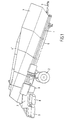
- Fig. 1 diagrammatically shows an example of a prior bulk bin;
- Figs. 2 and 3 diagrammatically show the construction of a prior roller screen unit;
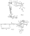
- Fig. 4 diagrammatically shows an embodiment of an apparatus according to the present invention; and
- Fig. 5 diagrammatically shows, in plan view, a detail of an apparatus according to the invention.
- The bulk bin shown diagrammatically in Fig. 1 in side-elevational view comprises a frame 1, which is mobile owing to the provision of wheels 2 and a
drawbar 3. The bulk bin proper is formed byupright sidewalls 4,4', between which is disposed an endless conveyor bottom, the bottom return run of which is designated by 5. The conveyor bottom is driven by adrive unit 6 arranged adjacent to the upper end of the elevation path. Disposed beyond the upper end of the elevation path is a roller screen unit, diagrammatically shown at 7, and shown in more detail in Figs. 2 and 3. Disposed underneath the roller screen unit is atransverse conveyor 8 for discharging material passed by the roller screen unit. In operation, the rollers of the roller screen unit are driven in such a manner that the produce is transported by the rollers to a secondtransverse conveyor 9, capable of transporting the produce further. - Fig. 2 shows a diagrammatic exploded view of the roller screen unit. The unit comprises a plurality of
rollers 10, each provided with asprocket 11 capable of cooperating with adrive chain 35, shown in Fig. 3, and arranged to rotate the rollers. - The shafts of the rollers are secured at both ends to the free ends of strips 12-16, of various lengths, and together with a connecting
strip 17 forming alinkage 18. One f:nd 19 of the connecting strip is fixedly, but pivotally connected to afixed frame member 20. In the embodiment shown, thisend 19 is adjacent to the roller located closest to the conveyor bottom (on the right-hand side in Fig. 2). - The adjustment of the mutual spacing between the rollers is effected by moving the shaft of one of the other rollers, preferably the shaft of the roller located closest to the product conveyor 9 (on the left-hand side of Fig. 2) transversely to its longitudinal direction. Owing to the operation of the linkage the other rollers will then be moved as well, and the interspace is changed.
- Fig. 3 shows the handle for adjusting the roller spacing.
Handle 21 is secured at one end to ashaft 22 carrying afixed pinion 23 arranged to cooperate with arack 25, constituted in this case by a length of chain secured to agirder 26 of the frame. -
Handle 21 is arranged to pivot relative to abearing block 27 secured toshaft 22, in a plane containing the shaft. So long as the handle is in its inoperative position, a pin secured to the handle engages with acogwheel 29 also fixedly secured toshaft 22, and the shaft can be turned by turning the handle according to thedouble arrow 28. If, however, the handle is pulled outwards in the plane referred to, the pin is no longer in engagement withcogwheel 29, and the handle is capable of being freely rotated relatively toshaft 22 andcogwheel 29. When the handle is turned while the pin is in engagement withcogwheel 29,pinion 23 rolls onrack 25, thereby taking alongshaft 22 transversely to its longitudinal direction. - Shaft 22 is journalled in a
transverse girder 30, provided at its ends withprojections 31 carryingrollers 32 which fall into a profile ofgirder 26. - Girder 30forms part of a
subframe carrying forks 34 coinciding with the shaft of the front roller. - When
handle 21 is turned, therefore,subframe 33 with the forks is moved relatively to thefixed frame members 20, so that the front roller and, via . the linkage, also the other rollers, are moved relatively to the rearmost roller, so that the interspace between the rollers is changed. - Fig. 3 further shows
drive chains 35 for the rollers, and a drive motor 36. - According to the present invention, the spacing between the rollers is continuously varied during operation, because experiments have surprisingly shown that this minimizes the chance of the roller screen unit becoming clogged.
- Such a continuous variation of the roller spacing in a roller screen unit can be accomplished in various ways.
- Fig. 4 shows, by way of example, one of the possible embodiments. The drive unit indicated at 6 in Fig. 1 is shown at 40 in Fig. 4. The drive unit comprises a first driven
pulley 41, which via abelt 42 drives alarger pulley 43. - By way of a transmission already present in the prior bulk bins, which is housed in a
gear box 46, asprocket 48, mounted in accordance with the present invention on an outwardly prolongedshaft 47, is driven. In operation, this sprocket drives, via achain 49, a second,smaller sprocket 50 to produce the desired rotary velocity. - Secured to
sprocket 50 is aneccentric crank 51, which is connected to acrank arm 52, which in turn is connected tooperating handle 21. Accordingly, when the drive unit is in operation, the operating handle is continuously moved up and down, as indicated by adouble arrow 53 in Fig. 4. As a result the spacing between the rollers of the roller screen unit is continuously varied as well. - In this case, too, the operating handle, now designated by 54, is, in operation, coupled with
sprocket 29, which is fixedly secured to the shaft, by means of a pin extending between the teeth of the sprocket. In the present embodiment, however, owing to the coupling with thecrank arm 52, the handle is no longer capable of being moved outwards, pivoting in the plane ofshaft 23. Accordingly, the operating handle is modified, in a manner to be described hereinafter in order that it may yet be disengaged fromsprocket 29. - By turning the sprocket with the operating handle, the initial spacing of the rollers can be adjusted.
- The accuracy of this adjustment is determined by the pitch of the teeth of
sprocket 29. - Fine adjustment has been rendered possible by providing thecrankarm 52 with an
arm member 55 that is adjustable relatively to the part secured to crank 51. In the embodiment shown, the adjustable arm member falls in a hollow portion of the part secured to the crank, in which it can be fixed in a desired position by means of awinged bolt 56. - Furthermore, operating
handle 54 is provided with a plurality ofholes 57. By selecting one of these holes as the point of attachment ofcrank arm member 55, the initial stroke length of the rollers can be adjusted. - The operating handle modified in accordance with the present invention is shown in more detail in plan view in Fig. 5.
- Operating
handle 54 is provided with agrip 58 and with a bearing block 59falling aroundshaft 22. Thesprocket 29, mounted onshaft 22, is shown in dotted lines. - Mounted on the operating handle next to bearing
block 59, for pivoting movement about ashaft 60 extending transversely to the plane of drawing, is an uncoupling mechanism. The uncoupling mechanism comprises aplate member 61, extending transversely to the operating handle, and provided with a bore to receiveshaft 60. -
Plate member 61 carries at its one end remote from the operating handle agrip 62 which via a tension spring 63 is connected to the operating handle.Plate member 61 is provided at its other end with apin 64 normally falling between two teeth ofsprocket 29 under the influence of tension spring 63. However, by movinggrip 62 in the direction of arrow 65,pin 64 can be brought out of engagement withsprocket 29. - The pin can then be placed between two other teeth of the sprocket to vary the initial spacing between the rollers.
- Furthermore, this construction serves as a safeguard. If, for example, a hard obstacle is present between the rollers,
shaft 22 and hencesprocket 29, is unable to complete the stroke set. In that case, however, pin 64 is capable of sliding over the teeth of the sprocket, thereby extending spring 63, so that any damage to the rollers or other structural parts is prevented. - Finally, the uncoupling mechanism is further provided with a plate-shaped
extension 66, secured to thefirst plate member 61, and disposed slightly above the body of the operating handle, which projection is provided with a vertical, threaded bore 67 to receive a winged bolt or like member. By means of this winged bolt the uncoupling mechanism can be fixed in the uncoupled position.
Claims (8)
Applications Claiming Priority (2)
| Application Number | Priority Date | Filing Date | Title |
|---|---|---|---|
| NL8203244A NL8203244A (en) | 1982-08-18 | 1982-08-18 | Dump hopper. |
| NL8203244 | 1982-08-18 |
Publications (3)
| Publication Number | Publication Date |
|---|---|
| EP0101637A2 EP0101637A2 (en) | 1984-02-29 |
| EP0101637A3 EP0101637A3 (en) | 1984-03-28 |
| EP0101637B1 true EP0101637B1 (en) | 1987-07-22 |
Family
ID=19840152
Family Applications (1)
| Application Number | Title | Priority Date | Filing Date |
|---|---|---|---|
| EP19830201200 Expired EP0101637B1 (en) | 1982-08-18 | 1983-08-17 | Bulk bin |
Country Status (3)
| Country | Link |
|---|---|
| EP (1) | EP0101637B1 (en) |
| DE (1) | DE3372588D1 (en) |
| NL (1) | NL8203244A (en) |
Families Citing this family (7)
| Publication number | Priority date | Publication date | Assignee | Title |
|---|---|---|---|---|
| GB8414662D0 (en) * | 1984-06-08 | 1984-07-11 | Tickhill Eng Co Ltd | Grading apparatus |
| DE69014465T2 (en) * | 1989-07-28 | 1995-06-29 | Pearson Richard Ltd | A lifting transport device and an agricultural separation device comprising a lifting transport device. |
| NL8902363A (en) * | 1989-09-21 | 1991-04-16 | Zijlstra & Bolhuis Bv | ROLLER Sieve Assembly. |
| NL8902907A (en) * | 1989-11-24 | 1991-06-17 | Zijlstra & Bolhuis Bv | Receiving hopper for agricultural products. |
| NL9100377A (en) * | 1991-02-28 | 1992-09-16 | Zijlstra & Bolhuis Bv | Receiving hopper for agricultural products. |
| NZ260822A (en) * | 1994-06-22 | 1997-06-24 | Transit Tank Int Inc | Transportable container for viscous material being half the height of a standard iso container |
| NL1016185C2 (en) * | 2000-09-14 | 2002-03-15 | Ploeger Agro B V | Equipment for simultaneous cleaning and transport of bulb and tuber crops comprises rollers located in frame and extending longitudinally between feed side and discharge side in transport unit |
Family Cites Families (7)
| Publication number | Priority date | Publication date | Assignee | Title |
|---|---|---|---|---|
| US3023904A (en) * | 1954-03-15 | 1962-03-06 | Brueckenbau Flender Gmbh | Screen for use in oscillating screening devices |
| FR1491435A (en) * | 1966-06-28 | 1967-08-11 | Const De Machines Agricoles Et | Device for cleaning potatoes and similar tubers |
| AU468224B2 (en) * | 1969-05-19 | 1975-12-10 | Jacob Donges And Walter Harold Donges | Roller adjustment mechanism |
| US3721345A (en) * | 1971-05-06 | 1973-03-20 | Milestone Inc | Method and machine for selecting potatoes of given size from massed potatoes of random size |
| SE406280B (en) * | 1977-10-03 | 1979-02-05 | Luossavaara Kiirunavaara Ab | TERM |
| DE2946312A1 (en) * | 1979-11-16 | 1981-05-27 | Günter 2148 Zeven Gerlach | Sugar beet screen - with screen bars running between endless straps in complex motion |
| DE3027651A1 (en) * | 1980-07-22 | 1982-03-18 | Gebr. Bütfering Maschinenfabrik, 4720 Beckum | Sugar beet sorting machine - has pairs of separately driven rollers forming sloping path, with mechanism controlling gaps between rollers |
-
1982
- 1982-08-18 NL NL8203244A patent/NL8203244A/en not_active Application Discontinuation
-
1983
- 1983-08-17 EP EP19830201200 patent/EP0101637B1/en not_active Expired
- 1983-08-17 DE DE8383201200T patent/DE3372588D1/en not_active Expired
Also Published As
| Publication number | Publication date |
|---|---|
| DE3372588D1 (en) | 1987-08-27 |
| EP0101637A2 (en) | 1984-02-29 |
| EP0101637A3 (en) | 1984-03-28 |
| NL8203244A (en) | 1984-03-16 |
Similar Documents
| Publication | Publication Date | Title |
|---|---|---|
| US4147017A (en) | Tomato harvester | |
| US5740922A (en) | Sizing screen with individual row spacing adjustability | |
| DE202013009251U1 (en) | Filler emptying and retracting device for used artificial turf pitches | |
| US4174755A (en) | Agitator assembly for a fruit-vine separator | |
| EP0101637B1 (en) | Bulk bin | |
| US4535894A (en) | Separator apparatus for peanuts and other seed crops | |
| US6182832B1 (en) | Easy-to-adjust grader | |
| DE19500022A1 (en) | Sieving unit, classifies difficult and sticky waste and organic materials | |
| US3211289A (en) | Sorting apparatus | |
| US3976214A (en) | Sugar cane planter | |
| DE3630028C1 (en) | Combined device for feeding, conveying, separating and crushing stony piles | |
| GB2067434A (en) | Potato harvester | |
| DE69816754T2 (en) | Agricultural machine with elevator system | |
| GB2048040A (en) | Root Crop Harvester | |
| EP0408589A1 (en) | Mobile or stationary disintegrating plant for minerals, in particular for lump-size material | |
| NL8103928A (en) | APPARATUS FOR CLEANING AND TRANSPORTING BULBS, ROOT AND CUBIC CROPS. | |
| CA1097583A (en) | Unloader for a horizontal silo | |
| JP3009590U (en) | Onion root cutting soil sieving device | |
| DE2544279C3 (en) | Discharge device | |
| US2244729A (en) | Grader | |
| US2894340A (en) | Oyster digger | |
| DE3811712C1 (en) | Mobile or stationary crusher device for minerals, in particular lumpy material | |
| NL8801438A (en) | DEVICE FOR SIZING BULBS AND TUBULAR CROPS. | |
| DE2809331C2 (en) | Device for digging crops, such as potatoes or the like. | |
| GB2077626A (en) | Soil-separating assemblies |
Legal Events
| Date | Code | Title | Description |
|---|---|---|---|
| PUAI | Public reference made under article 153(3) epc to a published international application that has entered the european phase |
Free format text: ORIGINAL CODE: 0009012 |
|
| PUAL | Search report despatched |
Free format text: ORIGINAL CODE: 0009013 |
|
| AK | Designated contracting states |
Designated state(s): BE DE FR GB NL |
|
| AK | Designated contracting states |
Designated state(s): BE DE FR GB NL |
|
| 17P | Request for examination filed |
Effective date: 19840201 |
|
| GRAA | (expected) grant |
Free format text: ORIGINAL CODE: 0009210 |
|
| AK | Designated contracting states |
Kind code of ref document: B1 Designated state(s): BE DE FR GB NL |
|
| REF | Corresponds to: |
Ref document number: 3372588 Country of ref document: DE Date of ref document: 19870827 |
|
| ET | Fr: translation filed | ||
| PLBE | No opposition filed within time limit |
Free format text: ORIGINAL CODE: 0009261 |
|
| STAA | Information on the status of an ep patent application or granted ep patent |
Free format text: STATUS: NO OPPOSITION FILED WITHIN TIME LIMIT |
|
| 26N | No opposition filed | ||
| REG | Reference to a national code |
Ref country code: FR Ref legal event code: ST |
|
| REG | Reference to a national code |
Ref country code: FR Ref legal event code: RC |
|
| PGFP | Annual fee paid to national office [announced via postgrant information from national office to epo] |
Ref country code: FR Payment date: 19980720 Year of fee payment: 16 |
|
| PGFP | Annual fee paid to national office [announced via postgrant information from national office to epo] |
Ref country code: GB Payment date: 19980810 Year of fee payment: 16 |
|
| PGFP | Annual fee paid to national office [announced via postgrant information from national office to epo] |
Ref country code: DE Payment date: 19980925 Year of fee payment: 16 |
|
| PG25 | Lapsed in a contracting state [announced via postgrant information from national office to epo] |
Ref country code: GB Free format text: LAPSE BECAUSE OF NON-PAYMENT OF DUE FEES Effective date: 19990817 |
|
| GBPC | Gb: european patent ceased through non-payment of renewal fee |
Effective date: 19990817 |
|
| PG25 | Lapsed in a contracting state [announced via postgrant information from national office to epo] |
Ref country code: FR Free format text: LAPSE BECAUSE OF NON-PAYMENT OF DUE FEES Effective date: 20000428 |
|
| PG25 | Lapsed in a contracting state [announced via postgrant information from national office to epo] |
Ref country code: DE Free format text: LAPSE BECAUSE OF NON-PAYMENT OF DUE FEES Effective date: 20000601 |
|
| PGFP | Annual fee paid to national office [announced via postgrant information from national office to epo] |
Ref country code: BE Payment date: 20000713 Year of fee payment: 18 |
|
| REG | Reference to a national code |
Ref country code: FR Ref legal event code: ST |
|
| PGFP | Annual fee paid to national office [announced via postgrant information from national office to epo] |
Ref country code: NL Payment date: 20000831 Year of fee payment: 18 |
|
| PG25 | Lapsed in a contracting state [announced via postgrant information from national office to epo] |
Ref country code: BE Free format text: LAPSE BECAUSE OF NON-PAYMENT OF DUE FEES Effective date: 20010831 |
|
| BERE | Be: lapsed |
Owner name: ZIJLSTRA & BOLHUIS B.V. Effective date: 20010831 |
|
| PG25 | Lapsed in a contracting state [announced via postgrant information from national office to epo] |
Ref country code: NL Free format text: LAPSE BECAUSE OF NON-PAYMENT OF DUE FEES Effective date: 20020301 |
|
| NLV4 | Nl: lapsed or anulled due to non-payment of the annual fee |
Effective date: 20020301 |