EP0101367B1 - Verzögerungsabhängiges Bremsventil - Google Patents
Verzögerungsabhängiges Bremsventil Download PDFInfo
- Publication number
- EP0101367B1 EP0101367B1 EP83401598A EP83401598A EP0101367B1 EP 0101367 B1 EP0101367 B1 EP 0101367B1 EP 83401598 A EP83401598 A EP 83401598A EP 83401598 A EP83401598 A EP 83401598A EP 0101367 B1 EP0101367 B1 EP 0101367B1
- Authority
- EP
- European Patent Office
- Prior art keywords
- magnet
- casing
- vehicle
- braking
- corrector
- Prior art date
- Legal status (The legal status is an assumption and is not a legal conclusion. Google has not performed a legal analysis and makes no representation as to the accuracy of the status listed.)
- Expired
Links
Images

Classifications
-
- B—PERFORMING OPERATIONS; TRANSPORTING
- B60—VEHICLES IN GENERAL
- B60T—VEHICLE BRAKE CONTROL SYSTEMS OR PARTS THEREOF; BRAKE CONTROL SYSTEMS OR PARTS THEREOF, IN GENERAL; ARRANGEMENT OF BRAKING ELEMENTS ON VEHICLES IN GENERAL; PORTABLE DEVICES FOR PREVENTING UNWANTED MOVEMENT OF VEHICLES; VEHICLE MODIFICATIONS TO FACILITATE COOLING OF BRAKES
- B60T8/00—Arrangements for adjusting wheel-braking force to meet varying vehicular or ground-surface conditions, e.g. limiting or varying distribution of braking force
- B60T8/26—Arrangements for adjusting wheel-braking force to meet varying vehicular or ground-surface conditions, e.g. limiting or varying distribution of braking force characterised by producing differential braking between front and rear wheels
- B60T8/28—Arrangements for adjusting wheel-braking force to meet varying vehicular or ground-surface conditions, e.g. limiting or varying distribution of braking force characterised by producing differential braking between front and rear wheels responsive to deceleration
- B60T8/282—Arrangements for adjusting wheel-braking force to meet varying vehicular or ground-surface conditions, e.g. limiting or varying distribution of braking force characterised by producing differential braking between front and rear wheels responsive to deceleration using ball and ramp
-
- B—PERFORMING OPERATIONS; TRANSPORTING
- B60—VEHICLES IN GENERAL
- B60T—VEHICLE BRAKE CONTROL SYSTEMS OR PARTS THEREOF; BRAKE CONTROL SYSTEMS OR PARTS THEREOF, IN GENERAL; ARRANGEMENT OF BRAKING ELEMENTS ON VEHICLES IN GENERAL; PORTABLE DEVICES FOR PREVENTING UNWANTED MOVEMENT OF VEHICLES; VEHICLE MODIFICATIONS TO FACILITATE COOLING OF BRAKES
- B60T8/00—Arrangements for adjusting wheel-braking force to meet varying vehicular or ground-surface conditions, e.g. limiting or varying distribution of braking force
- B60T8/26—Arrangements for adjusting wheel-braking force to meet varying vehicular or ground-surface conditions, e.g. limiting or varying distribution of braking force characterised by producing differential braking between front and rear wheels
- B60T8/30—Arrangements for adjusting wheel-braking force to meet varying vehicular or ground-surface conditions, e.g. limiting or varying distribution of braking force characterised by producing differential braking between front and rear wheels responsive to load
- B60T8/306—Arrangements for adjusting wheel-braking force to meet varying vehicular or ground-surface conditions, e.g. limiting or varying distribution of braking force characterised by producing differential braking between front and rear wheels responsive to load using hydraulic valves
Definitions
- the invention concerns braking correctors responsive to deceleration.
- a corrector valve is coupled to an inertia weight which is sensitive to deceleration and is capable of being displaced against return means when a predetermined deceleration is exceeded to cause the closure of said valve.
- the presence of the spring introduces undesirable rubbing during the displacement of the weight, generally constructed in the form of a ball, especially when the low value of the inertia forces acting on the latter are considered. It is then observed that the device lacks reliability, and also that its construction is relatively complex, principally when an adjustt- ment must be provided for the calibration of the spring.
- the present invention proposes to achieve such a return means by means of a magnet positioned at the rear, with regard to the direction of motion of the vehicle, of said inertia weight, the latter being made of a magnetic material and the surrounding components of non-magnetic materials.
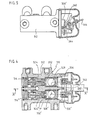
- the corrector 10 shown in Figure 1 consists of a casing 12 in which a stepped cavity 14a-14b is defined. Two ports for the inlet 16 and the outlet 18 open into the two ends of the cavity 14 in two chambers for the inlet 20 and the outlet 22, respectively.
- a stepped piston 24a-24b is mounted so as to slide in the cavity 14 between the inlet chamber 20 and the outlet chamber 22.
- a cylindrical housing 26 inside the piston 24 communicates with the inlet chamber 20 and houses a spherical inertia weight, or ball, 28.
- a passage 30 joins the housing 26 to the outlet chamber 22.
- a valve seat 32 is mounted at the mouth of this passage towards the housing 26, the ball 28 itself constituting a valve poppet capable of cooperating with the seat 32.
- the corrector 10 incorporates return means 34 exerting on the ball 28 a return force directed away from the seat 32.
- the return means 34 consists of a magnet 36 fixed to the casing 12 at the rear of the ball 28, with regard to the direction of motion of the vehicle.
- the ball 28 is made of magnetic material and the casing 12 and the piston 24 are made of non-magnetic material.
- an adjustable mounting 38 for the magnet 36 may be provided on the casing.
- the magnet 136 is mounted on an arm 140 which oscillates relative to the casing 12 and the arm 140 is linked to the suspension device of the vehicle (not shown).
- the restoring force exerted by the magnet 136 on the ball 128 will be variable as a function of the load on the vehicle, as will also the deceleration, which, when exceeded, will cause the ball to leave its rest position and come to be applied to the seat 132.
- the magnet 236 is fixed to the casing 212, and the arm 240, oscillating relative to the casing as a function of the load on the vehicle, carries a component 242 made of a material possessing a finite magnetic resistance.
- the force exerted by the latter on the former will be variable as a function of the load on the vehicle.
- the magnet 36,136,236 could also be constructed in the form of an electromagnet (not shown) controlled as a function of various parameters of the operation of the vehicle and/or of its braking system, or again as a combination of permanent magnet plus electromagnet (also not shown).
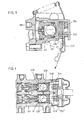
- the casing 312 incorporates two cavities 314 and 314' positioned in parallel and having two identical pistons 324 and 324' and two balls 328 and 328'.
- the two magnets 336 and 336' are mounted on a common plate 340 which pivots relative to the casing 312 under the action of a device with a cam 344 and a lever 346 as a function of the load on the vehicle.
- a device with a cam 344 and a lever 346 as a function of the load on the vehicle.
- the magnetic poles of the two magnets are reversed, as shown.
- the plate 340 is made of iron or of materials similar in this respect, which enables the lines of force to be looped opposite the magnets 336 and 336'.
- the magnetic coupling has been improved by introducing inserts 348, 348', 350 made from an iron base, or from materials similar in this respect, which enable the "Looped" magnetic lines of force M to be better concentrated.
- the operation could also be made dependent on the load on the vehicle not. by displacement of the magnets 336 and 336', but by displacement of a component forming a screen (not shown) of finite magnetic resistance (cf. Figure 3).
- the magnets 336, 336' could also be constructed as electromagnets or as combinations of permanent magnets plus electromagnets, as already outlined above. Finally it is possible to arrange for the inertia weight a slope or ramp to provide the shutting-off operation when empty, the magnet or magnets intervening to provide the shutting-off when loaded.
Landscapes
- Engineering & Computer Science (AREA)
- Transportation (AREA)
- Mechanical Engineering (AREA)
- Magnetically Actuated Valves (AREA)
- Hydraulic Control Valves For Brake Systems (AREA)
- Seats For Vehicles (AREA)
- Dynamo-Electric Clutches, Dynamo-Electric Brakes (AREA)
Claims (8)
Applications Claiming Priority (2)
| Application Number | Priority Date | Filing Date | Title |
|---|---|---|---|
| FR8213850 | 1982-08-09 | ||
| FR8213850A FR2531387A1 (fr) | 1982-08-09 | 1982-08-09 | Correcteur de freinage asservi a la deceleration |
Publications (3)
| Publication Number | Publication Date |
|---|---|
| EP0101367A1 EP0101367A1 (de) | 1984-02-22 |
| EP0101367B1 true EP0101367B1 (de) | 1986-02-26 |
| EP0101367B2 EP0101367B2 (de) | 1989-09-13 |
Family
ID=9276739
Family Applications (1)
| Application Number | Title | Priority Date | Filing Date |
|---|---|---|---|
| EP83401598A Expired EP0101367B2 (de) | 1982-08-09 | 1983-08-02 | Verzögerungsabhängiges Bremsventil |
Country Status (8)
| Country | Link |
|---|---|
| US (1) | US4560209A (de) |
| EP (1) | EP0101367B2 (de) |
| JP (1) | JPS5950842A (de) |
| AR (1) | AR231623A1 (de) |
| AU (1) | AU552777B2 (de) |
| DE (1) | DE3362300D1 (de) |
| ES (1) | ES8404653A1 (de) |
| FR (1) | FR2531387A1 (de) |
Families Citing this family (3)
| Publication number | Priority date | Publication date | Assignee | Title |
|---|---|---|---|---|
| DE4403030A1 (de) * | 1993-02-17 | 1994-08-18 | Lucas Ind Plc | Verzögerungsabhängiges Druckregelventil für Fahrzeugbremsanlagen |
| EP0633172A1 (de) * | 1993-07-09 | 1995-01-11 | Volkswagen Aktiengesellschaft | Umschaltbarer trägheitsgesteuerter Bremsdruckregler für hydraulische Kraftfahrzeug-Bremsanlagen |
| JP3709414B1 (ja) * | 2004-09-21 | 2005-10-26 | 住重機器システム株式会社 | 撹拌機 |
Family Cites Families (9)
| Publication number | Priority date | Publication date | Assignee | Title |
|---|---|---|---|---|
| DE470944C (de) * | 1926-09-14 | 1929-02-04 | Aeg | Einrichtung zur selbsttaetigen Regelung des Bremsvorganges bei Fahrzeugen |
| US3087761A (en) * | 1961-03-03 | 1963-04-30 | Kelsey Hayes Co | Brake pressure proportioning device |
| US3143379A (en) * | 1961-12-18 | 1964-08-04 | Kelsey Hayes Co | Brake pressure proportioning device |
| US3147045A (en) * | 1961-12-18 | 1964-09-01 | Kelsey Hayes Co | Brake pressure proportioning device |
| GB1079505A (en) * | 1963-07-31 | 1967-08-16 | Girling Ltd | Improvements relating to vehicle brakes |
| US3664713A (en) * | 1969-09-25 | 1972-05-23 | Kelsey Hayes Co | Skid control system utilizing vehicle deceleration |
| JPS5833141B2 (ja) * | 1978-12-27 | 1983-07-18 | 日信工業株式会社 | 車輌用ブレ−キ油圧制御弁装置 |
| JPS55164550A (en) * | 1979-06-05 | 1980-12-22 | Nissan Motor Co Ltd | Braking liquid pressure control valve |
| DE3041879A1 (de) * | 1980-11-06 | 1982-06-16 | Robert Bosch Gmbh, 7000 Stuttgart | Automatisch lastabhaengig einstellbarer bremskraftregler |
-
1982
- 1982-08-09 FR FR8213850A patent/FR2531387A1/fr active Granted
-
1983
- 1983-07-29 AU AU17421/83A patent/AU552777B2/en not_active Ceased
- 1983-08-02 DE DE8383401598T patent/DE3362300D1/de not_active Expired
- 1983-08-02 EP EP83401598A patent/EP0101367B2/de not_active Expired
- 1983-08-03 US US06/519,951 patent/US4560209A/en not_active Expired - Fee Related
- 1983-08-04 AR AR293810A patent/AR231623A1/es active
- 1983-08-08 ES ES524812A patent/ES8404653A1/es not_active Expired
- 1983-08-09 JP JP58144532A patent/JPS5950842A/ja active Pending
Also Published As
| Publication number | Publication date |
|---|---|
| ES524812A0 (es) | 1984-05-01 |
| JPS5950842A (ja) | 1984-03-24 |
| ES8404653A1 (es) | 1984-05-01 |
| EP0101367B2 (de) | 1989-09-13 |
| EP0101367A1 (de) | 1984-02-22 |
| DE3362300D1 (en) | 1986-04-03 |
| US4560209A (en) | 1985-12-24 |
| AU1742183A (en) | 1984-02-16 |
| FR2531387B1 (de) | 1984-11-30 |
| AR231623A1 (es) | 1985-01-31 |
| AU552777B2 (en) | 1986-06-19 |
| FR2531387A1 (fr) | 1984-02-10 |
Similar Documents
| Publication | Publication Date | Title |
|---|---|---|
| JP2947874B2 (ja) | ダンパ | |
| US4030756A (en) | Magnetic dampened inertial sensor for brake and sway controls | |
| EP0408631B1 (de) | Doppelrohrstossdämpfer | |
| US5379737A (en) | Electrically controlled timing adjustment for compression release engine brakes | |
| GB2208041A (en) | Electromechanical valve actuating apparatus | |
| WO1998057082A1 (en) | Valve mechanism | |
| US4813647A (en) | Electromagnetic actuator for controlling fluid flow | |
| EP0101367B1 (de) | Verzögerungsabhängiges Bremsventil | |
| US7066049B2 (en) | Wear-free accelerator pedal kick-down switch | |
| JPH037834B2 (de) | ||
| US4886091A (en) | Anti-shock directional control fluid valve | |
| US4518835A (en) | Force responsive switch | |
| JP3194950B2 (ja) | センサ | |
| US5028750A (en) | Impact sensor | |
| US4814564A (en) | Acceleration switch | |
| US4554938A (en) | Device for converting electric signals into pneumatic signals | |
| JPS56112350A (en) | Deceleration sensing valve | |
| US5402092A (en) | Electro-magnetic device | |
| US6289929B1 (en) | Pressure control valve for fuel tank | |
| US3786211A (en) | Differential pressure responsive magnetically actuated switch responsive only to sudden pressure changes | |
| US5614700A (en) | Integrating accelerometer capable of sensing off-axis inputs | |
| JPS5761860A (en) | Rotary delay device | |
| US4556028A (en) | Arrangement for regulating the idling speed of an internal combustion engine | |
| JPS626986Y2 (de) | ||
| US5050849A (en) | Vibration buffer |
Legal Events
| Date | Code | Title | Description |
|---|---|---|---|
| PUAI | Public reference made under article 153(3) epc to a published international application that has entered the european phase |
Free format text: ORIGINAL CODE: 0009012 |
|
| 17P | Request for examination filed |
Effective date: 19830808 |
|
| AK | Designated contracting states |
Designated state(s): DE GB IT SE |
|
| RAP1 | Party data changed (applicant data changed or rights of an application transferred) |
Owner name: BENDIX FRANCE |
|
| ITF | It: translation for a ep patent filed | ||
| GRAA | (expected) grant |
Free format text: ORIGINAL CODE: 0009210 |
|
| AK | Designated contracting states |
Designated state(s): DE GB IT SE |
|
| RAP2 | Party data changed (patent owner data changed or rights of a patent transferred) |
Owner name: BENDIX FRANCE |
|
| REF | Corresponds to: |
Ref document number: 3362300 Country of ref document: DE Date of ref document: 19860403 |
|
| PLBI | Opposition filed |
Free format text: ORIGINAL CODE: 0009260 |
|
| 26 | Opposition filed |
Opponent name: LUCAS INDUSTRIES PLC Effective date: 19861009 |
|
| ITF | It: translation for a ep patent filed | ||
| PUAH | Patent maintained in amended form |
Free format text: ORIGINAL CODE: 0009272 |
|
| STAA | Information on the status of an ep patent application or granted ep patent |
Free format text: STATUS: PATENT MAINTAINED AS AMENDED |
|
| 27A | Patent maintained in amended form |
Effective date: 19890913 |
|
| AK | Designated contracting states |
Kind code of ref document: B2 Designated state(s): DE GB IT SE |
|
| ITTA | It: last paid annual fee | ||
| PGFP | Annual fee paid to national office [announced via postgrant information from national office to epo] |
Ref country code: DE Payment date: 19940816 Year of fee payment: 12 |
|
| EAL | Se: european patent in force in sweden |
Ref document number: 83401598.4 |
|
| PG25 | Lapsed in a contracting state [announced via postgrant information from national office to epo] |
Ref country code: DE Effective date: 19960501 |
|
| PGFP | Annual fee paid to national office [announced via postgrant information from national office to epo] |
Ref country code: GB Payment date: 19960724 Year of fee payment: 14 |
|
| PGFP | Annual fee paid to national office [announced via postgrant information from national office to epo] |
Ref country code: SE Payment date: 19960815 Year of fee payment: 14 |
|
| PG25 | Lapsed in a contracting state [announced via postgrant information from national office to epo] |
Ref country code: GB Free format text: LAPSE BECAUSE OF NON-PAYMENT OF DUE FEES Effective date: 19970802 |
|
| PG25 | Lapsed in a contracting state [announced via postgrant information from national office to epo] |
Ref country code: SE Free format text: LAPSE BECAUSE OF NON-PAYMENT OF DUE FEES Effective date: 19970803 |
|
| GBPC | Gb: european patent ceased through non-payment of renewal fee |
Effective date: 19970802 |
|
| EUG | Se: european patent has lapsed |
Ref document number: 83401598.4 |