EP0101262A2 - Vorrichtungen zum Kontrollieren von Rudern eines Wasserfahrzeuges - Google Patents
Vorrichtungen zum Kontrollieren von Rudern eines Wasserfahrzeuges Download PDFInfo
- Publication number
- EP0101262A2 EP0101262A2 EP83304519A EP83304519A EP0101262A2 EP 0101262 A2 EP0101262 A2 EP 0101262A2 EP 83304519 A EP83304519 A EP 83304519A EP 83304519 A EP83304519 A EP 83304519A EP 0101262 A2 EP0101262 A2 EP 0101262A2
- Authority
- EP
- European Patent Office
- Prior art keywords
- hydroplane
- hydroplanes
- tilt
- hydraulic
- tilting
- Prior art date
- Legal status (The legal status is an assumption and is not a legal conclusion. Google has not performed a legal analysis and makes no representation as to the accuracy of the status listed.)
- Withdrawn
Links
- 230000007246 mechanism Effects 0.000 claims description 9
- 230000000694 effects Effects 0.000 claims description 5
- 230000001360 synchronised effect Effects 0.000 claims description 2
- 239000012530 fluid Substances 0.000 claims 3
- 239000010720 hydraulic oil Substances 0.000 description 4
- 239000000463 material Substances 0.000 description 2
- 239000003921 oil Substances 0.000 description 2
- 239000013535 sea water Substances 0.000 description 2
- RYGMFSIKBFXOCR-UHFFFAOYSA-N Copper Chemical compound [Cu] RYGMFSIKBFXOCR-UHFFFAOYSA-N 0.000 description 1
- 229910000881 Cu alloy Inorganic materials 0.000 description 1
- 229910000990 Ni alloy Inorganic materials 0.000 description 1
- 238000010276 construction Methods 0.000 description 1
- 239000010949 copper Substances 0.000 description 1
- 238000006073 displacement reaction Methods 0.000 description 1
- 210000004907 gland Anatomy 0.000 description 1
- 238000004519 manufacturing process Methods 0.000 description 1
- 230000009972 noncorrosive effect Effects 0.000 description 1
- XLYOFNOQVPJJNP-UHFFFAOYSA-N water Substances O XLYOFNOQVPJJNP-UHFFFAOYSA-N 0.000 description 1
Images


Classifications
-
- B—PERFORMING OPERATIONS; TRANSPORTING
- B63—SHIPS OR OTHER WATERBORNE VESSELS; RELATED EQUIPMENT
- B63G—OFFENSIVE OR DEFENSIVE ARRANGEMENTS ON VESSELS; MINE-LAYING; MINE-SWEEPING; SUBMARINES; AIRCRAFT CARRIERS
- B63G8/00—Underwater vessels, e.g. submarines; Equipment specially adapted therefor
- B63G8/14—Control of attitude or depth
- B63G8/18—Control of attitude or depth by hydrofoils
Definitions
- This invention relates to apparatus for controlling the hydroplanes of marine vessels and has particular, but not exclusive, application to hydroplanes for submarines.
- Control apparatus for submarines has previously been proposed wherein port and starboard hydroplanes are each mounted on the outer end of a stock carried on a crosshead.
- Each crosshead is slidably mounted on guide rails and the inner end of each stock is externally splined to co-operate with the internal splines of a common driving sleeve so that the stock can slide axially relative to its driving sleeve but cannot rotate relative thereto.
- Each driving sleeve is connected to a tilt lever mechanism through a torque tube for effecting angular movement of the sleeve about its axis in order to tilt the hydroplane mounted at the outer end of its associated stock.
- the tilt lever mechanism is actuated by an hydraulic piston and cylinder unit.
- Extending between the port and starboard crossheads is a main hydraulic piston and cylinder which can be hydraulically actuated to enable the crossheads to be moved in and out of their guide rails thus effecting extension and retraction of the hydroplanes.
- the external splines of the stocks slide relative to the associated internal splines of their respective sleeves.
- Tilting of each hydroplane is effected by actuating the tilting cylinder to operate the tilting lever assembly and cause the port and starboard torque tubes to be rotated. This causes rotation of the internally-splined sleeves and, due to the splines, rotation of the stocks and hydroplanes.
- Hydraulic locking mechanisms are provided to enable the hydroplanes to be locked in predetermined positions of tilt (e.g. 16° and O° respectively) as well as in extended or retracted positions.
- the above-described apparatus has a disadvantage in that its components require to be of a high tensile, nonferrous material because they are located outside the pressure hull of the vessel and are continually immersed in sea water.
- a further disadvantage is that accurate athwartship alignment of the crossheads is required. For this reason, inter alia, the manufacturing costs are high.
- An object of the present invention is to obviate or mitigate the aforesaid disadvantages.
- apparatus for controlling the hydroplanes of a marine vessel comprising a pair of hydroplane-carrying crossheads mounted for movement towards and away from each other to effect retraction and extension of the hydroplanes into and out of the vessel, first hydraulic means for effecting said retraction and extension movement of the crossheads, characterised in that there is provided second hydraulic means independently and operatively associated with each of the crossheads for effecting tilting of each hydroplane about an axis thereof, and synchronising means associated with said second hydraulic means for ensuring that tilting of each hydroplane is effected substantially in synchronism.
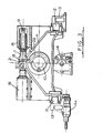
- Figs. 1 to 4 illustrate apparatus for controlling the port and starboard hydroplanes of a vessel, particularly a submarine in order to control the pitch of said submarine about a transverse axis.
- Figs. 1 to 3 only the mounting and operation of the starboard hydroplane is described but it will be appreciated that the port hydroplane is analogous in its construction and operation.
- the hydroplane blade (not shown) is fitted to a shaft or stock 10.
- the stock 10 is carried by a crosshead 11 which can be extended outboard or retracted into the hull of the submarine.
- the crosshead 11 is mounted on guide rails 12 supported on blocks 13 and the crosshead 11 can be moved outwardly or inwardly along the rails 12 under the influence of a main hydraulic cylinder 14.
- the cylinder 14 is supplied with hydraulic oil from an external hydraulic main and an hydraulic locking device 14a is provided to enable the hydroplanes to be locked in an extended or retracted position.
- the stock 10 is also rotatable about its own axis within limits in order to tilt the hydroplanes between, for example, 0° and 16°.
- Rotation of the stock lO is effected by a pair of hydraulically operated tilt cylinders 15 and 16 between which extends a common piston 17 having an elongated slot 18 therein.
- Each end of the piston 17 is recessed to receive a spring 19 (Fig. 3) which tends to urge the piston out of its respective cylinder.
- a pin 21 projects into the elongated slot 18 in the piston 17 and the pin 21 is connected to the stock 10 through the intermediary of a sleeve 22 (Fig. 2).
- Actuation of the cylinder 15 or 16, both of which are double-sealed, causes the piston 17 to be extended to engage the pin 21 and move it angularly about the axis of the stock lO in order to rotate the latter and consequently vary the angle of tilt of the hydroplane.
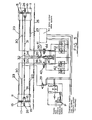
- Each tilt cylinder 15, 16 is supplied by reciprocating pump P with hydraulic pressure from the ring main system of the submarine by means of a telescopic hydraulic oil transfer tube 23. At its end remote from its associated tilt cylinder, the tube 23 is connected through a block 24 into the interior of pressure hull 25 (Fig. 5) of the submarine.
- Each telescopic tube 23 is of a sea water resistant copper/nickel alloy and the external portion of the tube is brazed to the pressure hull connection block 24 and the internal portion is brazed to the crosshead 11. Thus, no breakaway O-seal type pipe connections are used.
- a tilt lock hydraulically-operated piston and cylinder unit 26 is mounted adjacent the tilt cylinders 15, 16.
- the spring-loaded piston of the unit 26 terminates in a projection 27 which is engageable in recessses 28 in an extension of sleeve 22 to enable the hydroplane to be locked in a predetermined angle of tilt e.g. 0° or 16°.
- Hydraulic oil supply to the tilt lock unit 26 is controlled through a solenoid valve 29 which allows oil to be supplied to the unit 26 through a telescopic tube 30.
- the stock 11 of the hydroplane is connected through suitable mechanical linkage to a telescopic tilt angle indicating tube 31.
- a comparator comprising a toothed master and slave rack 36 and 37 respectively, the racks 36 and 37 being in mesh with a pinion 38 mounted on a rod 39 connected to a bleed off valve 40.
- the end of the master rack 36 remote from its rod 34 is connected through a servo control lever 41 to a customary servo control valve system.
- the starboard rod 34 and its associated master rack 36 move in the same direction as the starboard hydroplane blade tilt angle and provide mechanical feedback to the servo control gear.
- the rod 33 and its associated slave rack 37 move in the opposite direction to the master rack and the starboard hydroplane blade tilt angle. When the blade tilts, the pinion 38 rotates but there is no linear displacement of the pinion axis.
- the pinion axis moves linearly to actuate the hydraulic bleed off valve 40 thereby continuously synchronising the angular movement of the port and starboard blades.
- the tilt cylinders 15, 16 of the port and starboard hydroplanes are hydraulically operated through the servo control gear and pressure- compensated flow control valves 42 which are preset to give substantially identical tilt angle speeds to the port and starboard hydroplanes. Any angular misalignment of the blades during tilting is continuously compensated for by the synchronising mechanism as described above.
- the tilting system described above contains components some of which are internal of the pressure hull 25 and some which are external thereof.
- the complete system is maintained supercharged at a pressure e.g. 30 Bar above maximum sea pressure in order to prevent any ingress of water into the system.
- the tilt cylinders could be powered from an external hydraulic main in an emergency.
- a pair of solenoid valves (not shown) are actuated in order to cause the main cylinder 14 for each of the port and starboard hydroplanes to extend the hydroplanes laterally out of the submarine.
- each hydroplane When the hydroplanes are in the extended condition, the angle of tilt of each hydroplane is controlled by actuation of solenoid valves 43, 44 (Fig. 5) to cause .hydraulic oil to flow from the internal hydraulic system into either the tilt cylinder 15 or 16 for each hydroplane in order to vary the angle of tilt to the desired extent. If it is desired to lock each hydroplane blade at a set inclination e.g. 0° or 16°, the tilt lock unit 26 is actuated.
- the port and starboard blades are synchronised as regards angle of tilt by the synchronising gear in the manner previously described.
- oil transfer tubes 23 and 30 as well as the tilt angle indicating tubes 31 are telescopic in order to permit extension and retraction of the hydroplanes.
- a control apparatus for the hydroplanes of a submarine can be achieved in which the weight is nearly halved as compared with previously proposed arrangements.
- each crosshead houses its own dedicated tilt cylinder and lock which eliminates the need for splined torque tubes, associated bearings and ship support stools as in previously proposed arrangements, all of which were designed to transmit high sea slap loads and consequently were required to be manufactured from high-tensile non-corrosive materials which have to be surface coated for sliding during extension and retraction.
- tilt cylinders By fitting tilt cylinders on the crossheads, the actuating loads are self-contained and thus the load on the ship's structure is reduced by transmitting only the externally applied operating loads.
- hydroplane blades of greater area can be employed because of the dedicated arrangement of hydroplane control units which remove the movement for intermediate torque tubes and associated control gear of previously proposed arrangements.
- Such torque tubes and control gear were normally located between port and starboard hydroplanes thus limiting the area of the hydroplane blades used.
Landscapes
- Engineering & Computer Science (AREA)
- Mechanical Engineering (AREA)
- Aviation & Aerospace Engineering (AREA)
- Fluid-Pressure Circuits (AREA)
- Earth Drilling (AREA)
- Control Of Position Or Direction (AREA)
Applications Claiming Priority (2)
| Application Number | Priority Date | Filing Date | Title |
|---|---|---|---|
| GB8223264 | 1982-08-12 | ||
| GB8223264 | 1982-08-12 |
Publications (2)
| Publication Number | Publication Date |
|---|---|
| EP0101262A2 true EP0101262A2 (de) | 1984-02-22 |
| EP0101262A3 EP0101262A3 (de) | 1985-04-03 |
Family
ID=10532274
Family Applications (1)
| Application Number | Title | Priority Date | Filing Date |
|---|---|---|---|
| EP83304519A Withdrawn EP0101262A3 (de) | 1982-08-12 | 1983-08-04 | Vorrichtungen zum Kontrollieren von Rudern eines Wasserfahrzeuges |
Country Status (5)
| Country | Link |
|---|---|
| US (1) | US4530303A (de) |
| EP (1) | EP0101262A3 (de) |
| JP (1) | JPS5967196A (de) |
| KR (1) | KR840005695A (de) |
| ES (1) | ES8405702A1 (de) |
Families Citing this family (1)
| Publication number | Priority date | Publication date | Assignee | Title |
|---|---|---|---|---|
| KR101598383B1 (ko) * | 2014-08-04 | 2016-02-29 | 현대중공업 주식회사 | 대형 컨테이너 선박의 박스형 러더 |
Family Cites Families (10)
| Publication number | Priority date | Publication date | Assignee | Title |
|---|---|---|---|---|
| GB103050A (en) * | 1916-04-08 | 1917-01-11 | Eugene Schneider | Improvements in Submerging Rudder Apparatus for Submarines. |
| BE463924A (de) * | 1945-03-20 | 1946-04-30 | ||
| FR1088193A (fr) * | 1953-05-26 | 1955-03-03 | Perfectionnements apportés aux installations de commande à distance, notamment aux installations hydrauliques, destinées à communiquer à deux éléments semblables des déplacements identiques | |
| GB752744A (en) * | 1954-09-29 | 1956-07-11 | Franz August Sueberkrueb | Improvements relating to means for damping the rolling movement of ships |
| US2979010A (en) * | 1955-06-20 | 1961-04-11 | Sperry Rand Corp | Ship stabilization system |
| GB807411A (en) * | 1956-04-10 | 1959-01-14 | Norman Sinclair Mcnab | Apparatus for control and adjustment of stabilising fins and rudders of water craft |
| GB832715A (en) * | 1957-05-14 | 1960-04-13 | Saunders Roe Anglesey Ltd | Improvements relating to ships stabilizers |
| GB888452A (en) * | 1960-04-19 | 1962-01-31 | Franz Sueberkrub | Improvements in and relating to anti-roll stabilizers of ships |
| DE1506776C3 (de) * | 1967-04-05 | 1975-07-10 | Rheinstahl Nordseewerke Gmbh, 2970 Emden | Tiefenruderanlage für Unterwasserfahrzeuge |
| US4214704A (en) * | 1978-05-08 | 1980-07-29 | Rimrock Corporation | Reciprocator |
-
1983
- 1983-08-04 EP EP83304519A patent/EP0101262A3/de not_active Withdrawn
- 1983-08-11 US US06/522,007 patent/US4530303A/en not_active Expired - Fee Related
- 1983-08-11 ES ES524886A patent/ES8405702A1/es not_active Expired
- 1983-08-11 KR KR1019830003753A patent/KR840005695A/ko not_active Withdrawn
- 1983-08-12 JP JP58148681A patent/JPS5967196A/ja active Pending
Also Published As
| Publication number | Publication date |
|---|---|
| JPS5967196A (ja) | 1984-04-16 |
| KR840005695A (ko) | 1984-11-16 |
| US4530303A (en) | 1985-07-23 |
| EP0101262A3 (de) | 1985-04-03 |
| ES524886A0 (es) | 1984-06-16 |
| ES8405702A1 (es) | 1984-06-16 |
Similar Documents
| Publication | Publication Date | Title |
|---|---|---|
| US4028004A (en) | Feathering controllable pitch propeller | |
| US4523891A (en) | Propeller pitch change actuation system | |
| US3915111A (en) | Hydraulic marine propulsion and guidance system | |
| SE453985B (sv) | Roder for vattenfarkost | |
| US3112728A (en) | Twin screw power motor boat and transmission control | |
| EP4034459B1 (de) | Vorrichtung zur veränderung der betriebsstellungen eines auf einem motorisierten schiff befestigten oleodynamischen azimut-hecks | |
| KR20010024471A (ko) | 선박용 가변 피치 프로펠러 | |
| US3596626A (en) | Steering and tilting systems for marine vessels | |
| US3913517A (en) | Hydraulic steering mechanism for marine drive | |
| US3847107A (en) | Hydraulic marine propulsion and guidance system | |
| US2931443A (en) | Pitch control means for variable pitch propellers | |
| US4907992A (en) | Oil distribution box for a marine controllable pitch propeller | |
| US5231890A (en) | Shifting system for outboard drive unit | |
| US5427045A (en) | Steering cylinder with integral servo and valve | |
| US4530303A (en) | Apparatus for controlling hydroplanes of marine vessels | |
| KR19980024658A (ko) | 사이클로이드 프로펠라 | |
| KR102026082B1 (ko) | 가변 피치 프로펠러의 피치 피드백 장치 | |
| US2786539A (en) | Controllable-pitch propeller system | |
| US3778187A (en) | Controllable pitch propellers for marine vessels | |
| US2686569A (en) | Hydraulic controllable pitch propeller | |
| US3986475A (en) | Control arrangement | |
| US3232350A (en) | Controllable pitch propeller | |
| US4900280A (en) | Apparatus for detecting the pitch of a marine controllable pitch propeller | |
| US5213472A (en) | Inboard servo for marine controllable pitch propellers | |
| US3818853A (en) | Stop members in ships |
Legal Events
| Date | Code | Title | Description |
|---|---|---|---|
| PUAI | Public reference made under article 153(3) epc to a published international application that has entered the european phase |
Free format text: ORIGINAL CODE: 0009012 |
|
| AK | Designated contracting states |
Designated state(s): DE FR GB IT NL SE |
|
| PUAL | Search report despatched |
Free format text: ORIGINAL CODE: 0009013 |
|
| AK | Designated contracting states |
Designated state(s): DE FR GB IT NL SE |
|
| 17P | Request for examination filed |
Effective date: 19851002 |
|
| 17Q | First examination report despatched |
Effective date: 19860620 |
|
| D17Q | First examination report despatched (deleted) | ||
| STAA | Information on the status of an ep patent application or granted ep patent |
Free format text: STATUS: THE APPLICATION IS DEEMED TO BE WITHDRAWN |
|
| 18D | Application deemed to be withdrawn |
Effective date: 19880504 |
|
| RIN1 | Information on inventor provided before grant (corrected) |
Inventor name: BIRD, ROBERT MACTAGGART SCOTT (HOLDINGS) LTD. |