EP0101112B1 - Dispositif de transfert d'image - Google Patents
Dispositif de transfert d'image Download PDFInfo
- Publication number
- EP0101112B1 EP0101112B1 EP83201050A EP83201050A EP0101112B1 EP 0101112 B1 EP0101112 B1 EP 0101112B1 EP 83201050 A EP83201050 A EP 83201050A EP 83201050 A EP83201050 A EP 83201050A EP 0101112 B1 EP0101112 B1 EP 0101112B1
- Authority
- EP
- European Patent Office
- Prior art keywords
- image
- face
- exit face
- transfer apparatus
- fibres
- Prior art date
- Legal status (The legal status is an assumption and is not a legal conclusion. Google has not performed a legal analysis and makes no representation as to the accuracy of the status listed.)
- Expired
Links
- 239000000835 fiber Substances 0.000 claims description 65
- 239000011248 coating agent Substances 0.000 claims description 8
- 238000000576 coating method Methods 0.000 claims description 8
- 238000005253 cladding Methods 0.000 claims description 5
- 239000003086 colorant Substances 0.000 claims description 3
- 239000003365 glass fiber Substances 0.000 claims description 3
- 239000002356 single layer Substances 0.000 claims description 2
- 238000003491 array Methods 0.000 description 32
- 239000004973 liquid crystal related substance Substances 0.000 description 6
- 238000005452 bending Methods 0.000 description 2
- 230000005540 biological transmission Effects 0.000 description 2
- 230000003247 decreasing effect Effects 0.000 description 2
- 230000006835 compression Effects 0.000 description 1
- 238000007906 compression Methods 0.000 description 1
- 230000000694 effects Effects 0.000 description 1
- 238000010894 electron beam technology Methods 0.000 description 1
- 239000011888 foil Substances 0.000 description 1
- 230000003287 optical effect Effects 0.000 description 1
- 239000007787 solid Substances 0.000 description 1
Images


Classifications
-
- G—PHYSICS
- G02—OPTICS
- G02B—OPTICAL ELEMENTS, SYSTEMS OR APPARATUS
- G02B6/00—Light guides; Structural details of arrangements comprising light guides and other optical elements, e.g. couplings
- G02B6/04—Light guides; Structural details of arrangements comprising light guides and other optical elements, e.g. couplings formed by bundles of fibres
- G02B6/06—Light guides; Structural details of arrangements comprising light guides and other optical elements, e.g. couplings formed by bundles of fibres the relative position of the fibres being the same at both ends, e.g. for transporting images
Definitions
- the invention relates to an image transfer apparatus comprising at least one image-display device and an image magnifier which comprises a stack of single layer bands of fibres and has a substantially rectangular entrance face and a substantially rectangular exit face, the axial spacings of the separate fibers along two orthogonal directions at the exit face being greater than those at the entrance face all the fibres belonging to one band being arranged so that they extend without crossings one behind the other, all the bands having a first zone adjacent the entrance face in which the axial spacings of their fibres remain constant, all bands having a second zone adjacent the exit face in which the axial spacings decrease in the direction from the exit face towards the first zone, in each band in the second zone the fibres being bent, in the direction away from the exit face, first into the direction perpendicular and then parallel to the intersection of the band with the exit face, while the area where the first zone of each band passes into the second zone is located nearest to a first side of the exit face which extends perpendicularly to the intersection of the band with the exit face.
- Image transfer apparatus which makes use of fibre optic image magnifiers are generally known from DE-A-1,512,126.
- the image display device comprises a picture tube which is arranged adjacent the exit face of the image magnifier and whose axis is disposed parallel to one side of the rectangular exit face.
- the face plate of the picture tube is coupled to the entrance face of the image magnifier.
- An image displayed on the face plate is transferred to the exit face by internal reflection in the fibres, the light emerging from the fibres at the exit face.
- the image magnification depends on the ratio of the fibre pitch at the exit face and that at the entrance face.
- a specific fibre optic image magnifier of the type to which the invention pertains is known from GB-A-1,368,718.
- the fibre bands are stacked so that they form a solid block.
- the entrance face is disposed at one side of the block and the display device is to be arranged laterally offset with respect to the exit face.
- This means that the picture tube and the associated electronics are accommodated in a space around the image magnifier.
- an image transfer apparatus having a minimal volume.
- an image transfer apparatus of the type mentioned in the opening paragraph is characterized in that at least the second zone of each band is disposed as flatly as possible against the exit face, and in that the image display device is disposed substantially in the space behind the exit face, as viewed from the exit side.
- the invention is based on the recognition that by bending the fibre bands as flatly as possible against the exit face the volume required for the image magnifier can be reduced substantially.
- the space which now becomes available is employed to accommodate the image display device(s) with associated electronics and optics completely or partly depending on the dimensions. From the location where the fibres for the first time have the same pitch as at the entrance face, the fibres extend as a strip of parallel fibres to the entrance face, which depending on the arrangement of the image display device(s) may be arranged at a more or less arbitrary location in the space which has become available. This results in an image transfer apparatus whose volume is substantially equal to the volume previously occupied by the image magnifier alone.
- a first embodiment of an image transfer apparatus in accordance with the invention is characterized in that the entrance face is disposed in a plane which is substantially parallel to a plane perpendicular to the exit face, in which perpendicular plane is disposed a second orthogonal side of the exit face, perpendicular to the first orthogonal side.
- a second embodiment of an image transfer apparatus in accordance with the invention is characterized in that the entrance face is disposed . in a plane which is substantially parallel to a plane perpendicular to the exit face, in which perpendicular plane is disposed, the first orthogonal side of the exit face.
- a third embodiment of the image transfer apparatus in accordance with the invention is characterized in that one half of the fibre-bands is inclined mirror-symmetrically relative to the other half of the fibre-bands, the mid-perpendicular plane through the first orthogonal side of the exit face being the plane of symmetry.
- a fourth embodiment is characterized in that the exit face is formed by a face plate having a light-absorbing surface, which face plate is provided with apertures in which the fibre ends are arranged.
- a light-absorbing face plate does not reflect the ambient light, so that the contrast of the observed image is maximal.
- the face plate may comprise strips having a light-absorbing surface, in which or on which the fibre ends are arranged.
- the fibre ends . are provided with an anti-reflection coating. This precludes reflection of ambient light from the fibre ends.
- a fifth embodiment is characterized in that at the side of the exit face the fibre ends are formed with corrugations, at least in a direction parallel to one of the orthogonal sides of the exit face.
- the so-called viewing angle is comparatively small. This viewing angle is increased by forming the fibre ends with corrugations. Since for normal use of the apparatus the viewing angle should be magnified mainly in the horizontal direction, it suffices to form corrugations in the horizontal direction.
- a further embodiment is characterized in that a transparent plate is arranged on the exit face, the spaces between the fibre ends and the plate being filled with a paste, whose refractive index is equal to the refractive index of the plate. The plate provides protection against damage to the exit face. As they have the same refractive index the plate and the paste are optically similar, so that the spaces between the plate and the fibres will not disturb the image.
- a sixth embodiment is characterized in that a transparent plate is arranged on the exit face, which plate is formed with corrugations at the side which faces the exit face, which corrugations extend at least parallel to one of the orthogonal sides of the exit face.
- a corrugated plate instead of forming the fibres with corrugations it is possible to arrange a corrugated plate on the exit face. This plate may also serve as a protection for the exit face.
- a seventh embodiment is characterized in that at the entrance face the fibres are compressed in such a way that no spaces are left between the fibres.
- the fibres at the input face should be packed as densely as possible.
- the entrance face is compressed to ensure that no light is lost via the spaces between the fibres.
- An eighth embodiment is characterized in that at the entrance face the fibres are provided with an anti-reflection coating. This precludes a loss of light by reflection from the entrance face.
- a ninth embodiment is characterized in that at the entrance face the fibres are provided with a light-absorbing cladding. This precludes cross-talk of light coupled into a fibre to an adjacent fibre as a result of the compression of the fibres.
- a tenth embodiment is characterized in that the apparatus comprises a monochrome or a colour- picture tube as a display device.
- a further embodiment is characterized in that the picture tube is provided with a glass-fibre face plate.
- An eleventh embodiment is characterized in that the apparatus comprises three picture tubes which luminesce in the colours red, green and blue, a dichroic mirror arrangement, and a lens system.
- the dichroic optical cross the red the green and the blue image are brought into register and by means of the lens system the image is projected on the entrance face of the image magnifier, so that a coloured image can be observed at the exit face.
- a twelfth embodiment is characterized in that the image display device is formed by a controllable light modulator.
- This modulator may for example be an electro-optical display, such as a liquid-crystal display, an electrochrome display or an electrophoretic display, or another type of passive display such as a magneto-optical display.
- the display is coupled directly to the entrance face of the image magnifier.
- the display modulates the light from a light source in accordance with the information applied to the display.
- the image reflected by the display is projected onto the entrance face of the image magnifier.
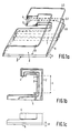
- Fig. 1a is a schematic perspective view of an image magnifier for an image transfer apparatus in accordance with the invention.
- the image magnifier comprises a bundle of fibres 2.
- the fibres are arranged in laminar fibre-arrays 3, three of which are designated 3.1, 3.2 and 3.3 in the Figure.
- the fibres 2 may be arranged on a supporting foil, either completely or at both ends.
- the laminar fibre-arrays 3 are superimposed.
- the laminar fibre arrays 3 have a pitch which is dictated by the desired image magnification.
- the rectangular exit face 5 has a first orthogonal side 6 and a second orthogonal side 7 perpendicular to the first orthogonal side 6.
- the ends of the fibres 2 are positioned perpendicularly to the exit face 5.
- the fibres 2 are shown as straight fibres whenever possible.
- the space required for bending the fibres 2 perpendicularly to the exit face 5 is the part whose depth is designated H in the Figure.
- Figure 1b is a plan view of a fibre array 3.
- the pitch of the fibres 2 changes from the pitch at the exit face 5 to the pitch of the fibres 2 at the entrance face 4. This is effected in such a way that the fibres 2 join each other at the location of the rectangle side 6.
- the distance B is equal for each fibre array 3 and depends on the number of fibres 2 in each fibre array 3. From the location where the fibres 2 joint each other the fibres 2 extend as a strip of parallel fibres 2 in a direction perpendicular to the rectangle side 7, after which they are diverted toward the entrance face 4.
- the entrance face 4 extends substantially parallel to a plane perpendicular to the exit face 5, in which perpendicular plane is disposed the rectangle side 7.
- the length of the part L of the strip of parallel fibres 2 which extends along the rectangle side 6 differs for each fibre array 3.
- the fibre arrays 3 are arranged at a minimal angle to the exit face 5.
- the fibre array 3.1 (see Fig. 1a) is disposed against the exit face 5.
- the depth of the image magnifier at the location of those parts of the fibre arrays 3 where the fibres 2 are spaced from each other within the range B is substantially smaller than atthe location where the fibres 2 are arranged in strips.
- the depth of the parts of the fibre arrays 3 within the range B is determined by the fibre pitch of the fibre arrays 3, the dimension B, and the diameter of the fibres 2.
- Figure 1 shows a front view of the image magnifier. The space which becomes available as a result of the smaller depth is utilized entirely orforthe greater part thereof to accommodate the image-display device(s) with associated electronics.
- the image magnifier comprises for example 800 fibre arrays 3 each comprising 1000 fibres 2 of a diameter of 0.125 mm.
- the pitch of the fibres 2 at the entrance face 4 is 0.125 mm.
- the entrance face 4 then has a size of approximately 0.125 x 0.100 m 2 .
- the pitch of the fibres 2 at the exit face 5 is 1.25 mm, so that the size of the exit face 5 is 1.25 x 1.00 m 2 .
- the image magnifier 1 transfers the image presented to the entrance face 4to the exit face 5 with a magnification factor of approximately 10.
- a safe curvature is approximately 1 cm, so that the distance H is approximately 1 cm.
- the distance B is approximately 12.5 cm.
- the height at the location of the parts of the fibre arrays 3 within the range B is then approximately 1.3 cm.
- the image magnifier 1 then has a depth of approximately 2.3 cm at the location of these parts of the fibre arrays 3, ie. for approximately 90% of the surface area of the exit face 5.
- the volume originally required for the image magnifier is 0.17 m 3 .
- FIG. 2a and 2b schematically represent a plan view and a side view of the apparatus.
- the image magnifier 21 is accommodated in a box-shaped enclosure 20, whose side 23 forms the exit face of the image magnifier 21.
- three monochrome picture tubes 24, 25 and 26 are arranged for producing a red, a green and a blue image respectively.
- the picture tubes 24, 25 and 26 are projection picture tubes with a high luminous efficiency and small dimensions.
- the face-plate diagonal of the picture tubes 24, 25 and 26 is for example 12 cm, so that the overall height of a picture tube is approximately 10 cm.
- the image of the picture tubes 24, 25 and 26 are imaged onto the entrance face 22 of the image magnifier 21 by means of an array of dichroic mirrors 27 and a lens system 28.
- the electronics for driving the picture tubes 24, 25 and 26 are accommodated in the schematically represented spaces 29. This results in a very compact image-transfer apparatus of small depth.
- the image transfer apparatus may be equipped with one monochrome or one colour picture tube.
- the input face of the image magnifier may then be coupled directly to the face plate of the picture tube.
- the face plate may then be constructed as a so-called glass fibre face plate, which is known per se from US-A-3,226,589..
- FIG. 3 A second embodiment of an image transfer apparatus in accordance with the invention will be described with reference to a plan view shown in Fig. 3. Identical parts bear the same reference numerals as in Fig. 2a.
- the present embodiment differs from the apparatus shown in Fig. 2a in that instead of picture tubes a passive liquid-crystal display 30 is used as display device.
- the liquid-crystal display 30 is coupled directly to the entrance face 22 of the image magnifier 21.
- the liquid-crystal display 30 is operated in the transmission mode.
- the apparatus comprises a light source 31 which projects a parallel light beam onto the display 30 by means of a lens system 32.
- the display 30 modulates the light in accordance with the picture information applied to the display.
- the liquid-crystal display may also be operated in reflection instead of in transmission, the reflected image being imaged onto the entrance face 22 of the image magnifier 21 by a lens system.
- the apparatus may be equipped with three displays, which modulate the light from a light source emitting red, green and blue light respectively. By means of lens systems the modulated light is imaged onto the entrance face of the image magnifier.
- the image-transfer apparatus may employ any kind of electro-optical display such as electrochrome and electrophoretic displays or a magneto-optical display or another type of passive display.
- Fig. 4 is a schematic perspective view of second version of an image magnifier for an image-transfer apparatus in accordance with the invention. Similar parts bear the same reference numerals as in Fig. 1a.
- the fibres 2 are again arranged in laminar fibre arrays 3 which extend at a minimal angle to the exit face 5.
- the pitch of the fibres 2 again changes, within a minimal distance B, from the pitch of the fibres 2 at the exit face 5 to the pitch of the fibres 2 at the entrance face 4, in such a way that the fibres 2 join each other substantially at the location of the orthogonal side 6 of the exit face 5.
- the fibres extend as a strip of parallel fibres 2 substantially in a direction perpendicular to the orthogonal side 6 of the exit face 4 and are subsequently bent towards the entrance face 4.
- the entrance face 4 extends substantially parallel to a plane perpendicular to the exit face 5 in which plane the rectangle side 6 is disposed.
- the image magnifier again has a very small depth. The space which thus becomes available is again utilized for accommodating the image display device(s) with the associated electronics and optics.
- An image transfer apparatus comprising an image magnifier as shown in Fig. 4 can be constructed in the same way as shown in Figs. 2a and 2b. Instead of three picture tubes the image transfer apparatus may again be equipped with one monochrome or colour picture tube or with a passive display.
- Fig. 4 is a schematic perspective view of a second version of an image magnifier for an image-transfer apparatus in accordance with the invention. Similar parts bear the same reference numerals as in Fig. 1a.
- the fibres 2 are again arranged in laminar fibre arrays 3 which extend at a minimal angle to the exit face 5.
- the pitch of the fibres 2 again changes, within a minimal distance B, from the pitch of the fibres 2 at the exit face 5 to the pitch of the fibres 2 at the entrance face 4, in such a way that the fibres 2 join each other substantially at the location of the orthogonal side 6 of the exit face 5.
- the fibres extend as a strip of parallel fibres 2 substantially in a direction perpendicular to the orthogonal side 6 of the exit face 4 and are subsequently bent towards the entrance face 4.
- the entrance face 4 extends substantially parallel to a plane perpendicular to the exit face 5 in which plane the rectangle side 6 is disposed.
- the image magnifier again has a very small depth. The space which thus becomes available is again utilized for accommodating the image display device(s) with the associated electronics and optics.
- An image transfer apparatus comprising an image magnifier as shown in Fig. 4 can be constructed in the same way as shown in Figs. 2a and 2b. Instead of three picture tubes the image transfer apparatus may again be equipped with one monochrome or colour picture tube or with a passive display.
- Fig. 5 is a schematic perspective view of a third version of an image magnifier for an image-transfer apparatus in accordance with the invention. Corresponding parts bear the same reference numerals as in Fig. 1a.
- the image magnifier is constructed mirror-symmetrically, the mid-perpendicular plane 10 through the orthogonal side 6 of the exit face 5 being the plane of symmetry.
- the fibres 2 are again arranged in laminar fibre arrays 3.
- One half of the fibre arrays is situated on one side of the mid-perpendicular plane 10 and the other half of the fibre arrays, of which the fibre arrays 3.1', 3.2' and 3.3' are shown in the Figure, is disposed mirror-symmetrically on the other side of the mid-perpendicular plane 10. All fibre arrays 3 again make a minimal angle with the exit face 5. In the fibre arrays 3 the pitch of the fibres 2 again changes within a minimal distance from the pitch of the fibres 2 at the exit face 5 to the pitch of the fibres 2 at the entrance face 4 in such a way that the fibres 2 substantially join each other at the level of the rectangle side 6 of the exit face 5.
- the Figure does not show how the fibres 2 extend from the location where the fibres 2 join each other to the entrance face 4 as a strip of parallel fibres 2. Only the positions of the ends of the fibres 2 at the entrance face 4 are shown.
- the fibres of the fibre arrays 3.1 to 3.3 are designated 2.1 to 2.6 and those of the fibre arrays 3.1' to 3.3' are designated 2.1' to 2.6'.
- the image magnifier again has a very small depth over a substantial part of the surface area of the exit face 5.
- the space which becomes available is again employed to accommodate image display device(s) with associated electronics and optics.
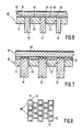
- Fig. 6 is a sectional view of a part of a first version of the exit face of the image magnifier.
- the exit face 40 is formed by a face plate 41 in which the ends 43 of the fibres 42 are arranged. The fibre ends occupy only 1% of the surface area of the face plate 41.
- the face plate 41 has a light-absorbing matt-black surface 44, which does not reflect the ambient light. This results in an optimum contrast of the image which is observed.
- On the face plate 41 a transparent plate 45 is arranged which is provided with an anti-reflection coating 48. At the side facing the face plate 41 this transparent plate 45 is formed with corrugations 46. These corrugations 46 enlarge the exit angle of the light from the fibres 42 and thus the viewing angle of the observer. Since during normal use a large viewing angle is mainly -required in the horizontal direction, the corrugations 46 need only be formed in one direction, namely parallel to the vertical rectangle side of the exit face 40.
- Fig. 7 is a sectional view of a part of a second version of the exit face.
- the ends 43 of the fibres 42 are corrugated instead of a plate.
- a transparent plate 45 is arranged for the purpose of protection, which plate is provided with an anti-reflection coating 48.
- the spaces between the plate 45 and the face plate 41 are filled with a paste 47 whose refractive index is equal to that of the plate 45.
- the plate 45 and the paste 47 are therefore optically identical, so that the image will not be disturbed by light which emerges from the fibres 42 as a result of refraction at the inside of the plate 45.
- the exit face 40 may alternatively be formed by a stack of matt-black strips, which are formed with slots in which the fibres are fitted.
- Fig. 8 is a view of a part of the entrance face of the image magnifier.
- the fibres 50 comprise a core 51 with a cladding 52.
- the cladding 52 which is as thin as possible, has a smaller refractive index than the core 51 and therefore reflects the light which enters the core 51 via the end faces.
- the spaces between the originally round fibres 50 are eliminated by compressing the entrance face, thereby deforming the fibres 50.
- round fibres 50 it is possible to employ fibres of triangular, square or hexagonal cross-section.
- the fibres are provided with an anti-reflection coating in order to minimize reflection of the light to be coupled in.
- the cladding 52 is suitably provided with a light-absorbing surface in order to preclude cross-talk of light coupled into one fibre to another fibre.
- the fibres 50 are offset relative to each other. This is in order to minimize moire-effects of the pattern of parallel lines written in a picture tube by the electron beam.
Landscapes
- Physics & Mathematics (AREA)
- General Physics & Mathematics (AREA)
- Optics & Photonics (AREA)
- Optical Fibers, Optical Fiber Cores, And Optical Fiber Bundles (AREA)
- Transforming Electric Information Into Light Information (AREA)
Claims (18)
Applications Claiming Priority (2)
| Application Number | Priority Date | Filing Date | Title |
|---|---|---|---|
| NL8202935A NL8202935A (nl) | 1982-07-21 | 1982-07-21 | Beeldoverdrachtsinrichting. |
| NL8202935 | 1982-07-21 |
Publications (2)
| Publication Number | Publication Date |
|---|---|
| EP0101112A1 EP0101112A1 (fr) | 1984-02-22 |
| EP0101112B1 true EP0101112B1 (fr) | 1987-10-14 |
Family
ID=19840061
Family Applications (1)
| Application Number | Title | Priority Date | Filing Date |
|---|---|---|---|
| EP83201050A Expired EP0101112B1 (fr) | 1982-07-21 | 1983-07-15 | Dispositif de transfert d'image |
Country Status (6)
| Country | Link |
|---|---|
| US (1) | US4871228A (fr) |
| EP (1) | EP0101112B1 (fr) |
| JP (1) | JPS5928777A (fr) |
| DE (1) | DE3374087D1 (fr) |
| ES (1) | ES8404519A1 (fr) |
| NL (1) | NL8202935A (fr) |
Families Citing this family (13)
| Publication number | Priority date | Publication date | Assignee | Title |
|---|---|---|---|---|
| CA1314742C (fr) * | 1986-12-12 | 1993-03-23 | Hiromu Terada | Faisceau de fibres optiques |
| FR2634087A1 (fr) * | 1988-07-08 | 1990-01-12 | Thomson Csf | Systeme de visualisation d'image couleur utilisant un melangeur optique a fibres ordonnees |
| US4952022A (en) * | 1989-03-02 | 1990-08-28 | Xerox Corporation | Fiber optic line illuminator with deformed end fibers and method of making same |
| US5107534A (en) * | 1989-09-25 | 1992-04-21 | Hazeltine Corporation | Flat panel display system and method |
| US5303085A (en) * | 1992-02-07 | 1994-04-12 | Rallison Richard D | Optically corrected helmet mounted display |
| EP0663111B1 (fr) * | 1993-08-04 | 1996-11-13 | Koninklijke Philips Electronics N.V. | Composant d'imagerie multimode et laser annulaire pourvu d'un tel composant |
| US5991087A (en) * | 1993-11-12 | 1999-11-23 | I-O Display System Llc | Non-orthogonal plate in a virtual reality or heads up display |
| JP3911305B2 (ja) * | 1996-04-22 | 2007-05-09 | 浜松ホトニクス株式会社 | ファイバ光学プレート |
| JP3642975B2 (ja) * | 1999-03-30 | 2005-04-27 | フジノン株式会社 | 露光装置 |
| US6418254B1 (en) * | 1999-06-04 | 2002-07-09 | Shizuki Electric Company, Inc. | Fiber-optic display |
| US7297931B2 (en) | 2003-10-20 | 2007-11-20 | Lynx System Developers, Inc. | Method and apparatus to effectively reduce a non-active detection gap of an optical sensor |
| TWI251435B (en) * | 2004-12-22 | 2006-03-11 | Lite On Technology Corp | Light sensing element having two functions |
| WO2007149898A2 (fr) * | 2006-06-21 | 2007-12-27 | Ronald Smith | Système d'affichage optique et système et procédé d'affichage optique |
Citations (1)
| Publication number | Priority date | Publication date | Assignee | Title |
|---|---|---|---|---|
| GB1368718A (en) * | 1971-08-09 | 1974-10-02 | Zeiss Stiftung | Process and apparatus for optically transmitting images with constant magnification |
Family Cites Families (26)
| Publication number | Priority date | Publication date | Assignee | Title |
|---|---|---|---|---|
| US3043910A (en) * | 1958-05-19 | 1962-07-10 | American Optical Corp | Fiber optical image transfer devices |
| US3226589A (en) * | 1960-03-24 | 1965-12-28 | American Optical Corp | Fiber type light transferring devices and method of making the same |
| US3323886A (en) * | 1963-05-01 | 1967-06-06 | American Optical Corp | Radiation absorption heating of a bundle of glass fibers |
| US3519742A (en) * | 1964-02-25 | 1970-07-07 | Ncr Co | Photochromic display using cathode ray tube |
| US3402000A (en) * | 1964-09-10 | 1968-09-17 | Norman H. Crawford | Fiber optical image enlarger |
| DE1512126A1 (de) * | 1967-02-21 | 1970-04-02 | Siegfried Burkhardt | UEbertragungseinrichtung,insbesondere fuer Fernsehbilder |
| US3604780A (en) * | 1969-05-01 | 1971-09-14 | Ibm | Three-dimensional fiber optic display |
| US3907403A (en) * | 1969-07-28 | 1975-09-23 | Matsushita Electric Industrial Co Ltd | Fibre-optics faceplate observable with high-intensity ambient illumination |
| US3668304A (en) * | 1970-06-29 | 1972-06-06 | Bell Telephone Labor Inc | Single pickup tube color television camera |
| JPS4923909B1 (fr) * | 1970-12-17 | 1974-06-19 | ||
| US3853658A (en) * | 1971-07-12 | 1974-12-10 | R Ney | Fiber optical image magnifier panel and method of manufacture |
| SE362148B (fr) * | 1972-04-20 | 1973-11-26 | Aga Ab | |
| DE2233806A1 (de) * | 1972-07-10 | 1974-01-24 | Braun Ag | Lichtleitendes einbauteil zur darstellung optischer informationen |
| US3937561A (en) * | 1974-12-02 | 1976-02-10 | The United States Of America As Represented By The Secretary Of The Navy | Liquid crystal optical image attenuator |
| GB1552002A (en) * | 1975-07-14 | 1979-09-05 | Yardley Prod Corp | Metal insert adapted to be embedded in a cavity in a workpiece |
| US4116739A (en) * | 1976-11-26 | 1978-09-26 | New York Institute Of Technology | Method of forming an optical fiber device |
| JPS5442263A (en) * | 1977-09-07 | 1979-04-04 | Mima Jiyurii Yuugen | Personal ornament |
| US4173391A (en) * | 1978-04-06 | 1979-11-06 | New York Institute Of Technology | Three dimensional display |
| US4427977A (en) * | 1981-08-06 | 1984-01-24 | The United States Of America As Represented By The Secretary Of The Navy | Video image simulation apparatus |
| US4786139A (en) * | 1984-02-01 | 1988-11-22 | Advance Display Technologies, Inc. | Optical fiber light transfer apparatus, method and apparatus for making same |
| US4650280A (en) * | 1984-02-01 | 1987-03-17 | Sedlmayr Steven R | Fiber optic light transfer device, modular assembly, and method of making |
| US4773730A (en) * | 1984-02-01 | 1988-09-27 | Advance Display Technologies, Inc. | Fiber optic light transfer devices and assemblies |
| US4747648A (en) * | 1985-01-24 | 1988-05-31 | Drd Ltd. | Optical fiber display and optical train for same |
| US4738510A (en) * | 1985-03-28 | 1988-04-19 | Sansom William L | Fiber optic display device and method for producing images for same |
| CA1314742C (fr) * | 1986-12-12 | 1993-03-23 | Hiromu Terada | Faisceau de fibres optiques |
| US4815816A (en) * | 1987-05-12 | 1989-03-28 | Rts Laboratories, Inc. | Image transportation device using incoherent fiber optics bundles and method of using same |
-
1982
- 1982-07-21 NL NL8202935A patent/NL8202935A/nl not_active Application Discontinuation
-
1983
- 1983-07-15 DE DE8383201050T patent/DE3374087D1/de not_active Expired
- 1983-07-15 EP EP83201050A patent/EP0101112B1/fr not_active Expired
- 1983-07-18 JP JP58129589A patent/JPS5928777A/ja active Pending
- 1983-07-19 ES ES524239A patent/ES8404519A1/es not_active Expired
-
1986
- 1986-02-07 US US06/828,085 patent/US4871228A/en not_active Expired - Fee Related
Patent Citations (1)
| Publication number | Priority date | Publication date | Assignee | Title |
|---|---|---|---|---|
| GB1368718A (en) * | 1971-08-09 | 1974-10-02 | Zeiss Stiftung | Process and apparatus for optically transmitting images with constant magnification |
Also Published As
| Publication number | Publication date |
|---|---|
| US4871228A (en) | 1989-10-03 |
| ES524239A0 (es) | 1984-04-16 |
| EP0101112A1 (fr) | 1984-02-22 |
| ES8404519A1 (es) | 1984-04-16 |
| JPS5928777A (ja) | 1984-02-15 |
| NL8202935A (nl) | 1984-02-16 |
| DE3374087D1 (en) | 1987-11-19 |
Similar Documents
| Publication | Publication Date | Title |
|---|---|---|
| US6685792B2 (en) | Method of making a small inlet optical panel | |
| US6519400B2 (en) | Ultrathin optical panel and a method of making an ultrathin optical panel | |
| EP0101112B1 (fr) | Dispositif de transfert d'image | |
| US7222969B2 (en) | Split image optical display | |
| MXPA01002124A (es) | Proyector optico de panel de pantalla delgada. | |
| US6400876B1 (en) | Ultrathin optical panel and a method of making an ultrathin optical panel | |
| EP0802443A1 (fr) | Affichage a cristaux liquides | |
| US20030174978A1 (en) | Planar optical waveguides for optical panel having gradient refractive index core | |
| US6317545B1 (en) | Stepped inlet optical panel | |
| KR20010074701A (ko) | 투명한 시임 디스플레이 패널과 그 제조 방법 | |
| KR100501789B1 (ko) | 콤팩트형 조명 장치 | |
| JP2000275572A (ja) | 投影装置 | |
| JPS61138902A (ja) | イメ−ジガイド |
Legal Events
| Date | Code | Title | Description |
|---|---|---|---|
| PUAI | Public reference made under article 153(3) epc to a published international application that has entered the european phase |
Free format text: ORIGINAL CODE: 0009012 |
|
| AK | Designated contracting states |
Designated state(s): DE FR GB NL |
|
| 17P | Request for examination filed |
Effective date: 19840308 |
|
| GRAA | (expected) grant |
Free format text: ORIGINAL CODE: 0009210 |
|
| AK | Designated contracting states |
Kind code of ref document: B1 Designated state(s): DE FR GB NL |
|
| REF | Corresponds to: |
Ref document number: 3374087 Country of ref document: DE Date of ref document: 19871119 |
|
| ET | Fr: translation filed | ||
| PLBE | No opposition filed within time limit |
Free format text: ORIGINAL CODE: 0009261 |
|
| STAA | Information on the status of an ep patent application or granted ep patent |
Free format text: STATUS: NO OPPOSITION FILED WITHIN TIME LIMIT |
|
| 26N | No opposition filed | ||
| PGFP | Annual fee paid to national office [announced via postgrant information from national office to epo] |
Ref country code: NL Payment date: 19900731 Year of fee payment: 8 |
|
| PG25 | Lapsed in a contracting state [announced via postgrant information from national office to epo] |
Ref country code: NL Effective date: 19920201 |
|
| NLV4 | Nl: lapsed or anulled due to non-payment of the annual fee | ||
| PGFP | Annual fee paid to national office [announced via postgrant information from national office to epo] |
Ref country code: GB Payment date: 19920630 Year of fee payment: 10 |
|
| PGFP | Annual fee paid to national office [announced via postgrant information from national office to epo] |
Ref country code: FR Payment date: 19920729 Year of fee payment: 10 |
|
| PGFP | Annual fee paid to national office [announced via postgrant information from national office to epo] |
Ref country code: DE Payment date: 19920928 Year of fee payment: 10 |
|
| PG25 | Lapsed in a contracting state [announced via postgrant information from national office to epo] |
Ref country code: GB Effective date: 19930715 |
|
| GBPC | Gb: european patent ceased through non-payment of renewal fee |
Effective date: 19930715 |
|
| PG25 | Lapsed in a contracting state [announced via postgrant information from national office to epo] |
Ref country code: FR Effective date: 19940331 |
|
| PG25 | Lapsed in a contracting state [announced via postgrant information from national office to epo] |
Ref country code: DE Effective date: 19940401 |
|
| REG | Reference to a national code |
Ref country code: FR Ref legal event code: ST |