EP0100410A2 - High strength and high elongation carbon fiber bundle and process for producing the same - Google Patents
High strength and high elongation carbon fiber bundle and process for producing the same Download PDFInfo
- Publication number
- EP0100410A2 EP0100410A2 EP83105414A EP83105414A EP0100410A2 EP 0100410 A2 EP0100410 A2 EP 0100410A2 EP 83105414 A EP83105414 A EP 83105414A EP 83105414 A EP83105414 A EP 83105414A EP 0100410 A2 EP0100410 A2 EP 0100410A2
- Authority
- EP
- European Patent Office
- Prior art keywords
- fiber bundle
- carbon fiber
- monofilament
- strength
- elongation
- Prior art date
- Legal status (The legal status is an assumption and is not a legal conclusion. Google has not performed a legal analysis and makes no representation as to the accuracy of the status listed.)
- Granted
Links
Images

Classifications
-
- D—TEXTILES; PAPER
- D01—NATURAL OR MAN-MADE THREADS OR FIBRES; SPINNING
- D01F—CHEMICAL FEATURES IN THE MANUFACTURE OF ARTIFICIAL FILAMENTS, THREADS, FIBRES, BRISTLES OR RIBBONS; APPARATUS SPECIALLY ADAPTED FOR THE MANUFACTURE OF CARBON FILAMENTS
- D01F9/00—Artificial filaments or the like of other substances; Manufacture thereof; Apparatus specially adapted for the manufacture of carbon filaments
- D01F9/08—Artificial filaments or the like of other substances; Manufacture thereof; Apparatus specially adapted for the manufacture of carbon filaments of inorganic material
- D01F9/12—Carbon filaments; Apparatus specially adapted for the manufacture thereof
- D01F9/14—Carbon filaments; Apparatus specially adapted for the manufacture thereof by decomposition of organic filaments
- D01F9/20—Carbon filaments; Apparatus specially adapted for the manufacture thereof by decomposition of organic filaments from polyaddition, polycondensation or polymerisation products
- D01F9/21—Carbon filaments; Apparatus specially adapted for the manufacture thereof by decomposition of organic filaments from polyaddition, polycondensation or polymerisation products from macromolecular compounds obtained by reactions only involving carbon-to-carbon unsaturated bonds
- D01F9/22—Carbon filaments; Apparatus specially adapted for the manufacture thereof by decomposition of organic filaments from polyaddition, polycondensation or polymerisation products from macromolecular compounds obtained by reactions only involving carbon-to-carbon unsaturated bonds from polyacrylonitriles
Definitions
- This invention relates to a high strength and high elongation carbon fiber bundle and a process for producing the same. More particularly, this invention relates to a carbon fiber bundle whose excellent mechanical properties as carbon fiber can be substantially completely reflected in the mechanical properties of composite materials prepared therefrom and to a process for producing the same.
- carbon fiber has heretofore been applied to a variety of uses such as aeronautical and aerospace structural materials and materials for sporting goods such as tennis rackets, golf shafts, fishing rods and the like, and it is now intended to apply to a wider field such as a structural material connected with transportation such as automobiles and vessels.
- high strength carbon fibers are produced by a method which includes using an acrylonitrile fiber as a starting material, heating the starting material in an oxidizing atmosphere of at least 200° C to convert it into a heat-stabilized (oxidized) fiber, then carbonizing the oxidized fiber by heating the fiber in an inert atmosphere of at least 800 . 0 C and, if necessary, heating the carbonized fiber to higher temperature to graphitize the fiber to obtain a carbon fiber or a graphite fiber. Accordingly, in such a process, high cost is required for the baking equipment, and much electrical and thermal energy is required in the baking operation.
- a starting material typified by the above-mentioned acrylonitrile fiber is used as fiber assemblies such as tow or band form fibers.
- a fiber assembly is not only difficult to have uniform fiber properties as a starting material but also difficult to prevent mutual adhesion among monofilaments constituting the fiber assemblies in the above-mentioned heat stabilization (heat-stabilizing or oxidation) and carbonization steps and to obtain a uniform treatment effect in after-treatments, such as surface oxidation, of the produced carbon fiber. Accordingly, as the number of the monofilaments constituting the fiber assembly increases, uniformity in properties among them decreases rapidly.
- Japanese Patent Laid-open No. 88222/1979 it is disclosed in Japanese Patent Laid-open No. 88222/1979 that it is possible to obtain a carbon fiber which, in a load-elongation curve of Carbon fiber, has a maximum peak in the region of elongation equal to or greater than 0.7% and has no load maximum peak or shoulder due to the interaction among the fibers in the region of elongation equal to or smaller than 0.5%, by preparing an acrylic fiber having excellent openability by special drawing and thereby lowering mutual adhesion among the fibers during the oxidation step. Namely, a carbon fiber bundle is disclosed which is small in the number of monofilaments which are broken in the region of low elongation in a load-elongation test. It is also disclosed in Japanese Patent Laid-opens Nos.
- an acrylic fiber applied with a silicone oil finish is useful as a material fiber for producing carbon fibers having excellent in physical properties, because adhesion among the monofilaments themselves can be effectively prevented in a process of producing fibers and oxidation steps of said fiber.
- these conventional carbon fibers have excellent properties as carbon fiber, and property difference among the monofilaments constituting the carbon fibers are improved, they can not show fully improved physical properties when they are combined with resins to form composite materials and have a problem that the excellent properties of a carbon fiber itself can not be reflected fully in properties as a composite material.
- the inventors of this invention has studied eagerly to improve the strength and elongation of a carbon fiber and, at the same time, to obtain a carbon fiber bundle capable of providing composite materials in which the above improved properties of the carbon fiber can be reflected fully and, as a result, we have reached this invention.
- This invention for achieving the foregoing objects is characterized in that, when-measured according to the strand tensile test as stipulated in the below-described Japanese Industrial Standard (JIS) R-7601, the strength of the carbon fiber bundle is about 420 to 650 kg/mm 2 , and the elongation is about 1.7 to 2.5%, and in that surface of a test piece used in the test, the average length of the protruding carbon fiber broken ends is 1.0 to .5.0 times, preferably 1.2 to 3.0 times the monofilament diameter.
- JIS Japanese Industrial Standard
- the strand test piece prepared according to the JIS-R-7601 is previously covered with adhesive tape for the purpose of preventing scattering of broken pieces when the test piece is broken, and then the test piece is stretched and broken by using "Tensilon" tester ("Tensilon" UTM-III LH, manufactured by Toyo-Baldwin Co.) at a crosshead speed of 5 cm/min.
- "Tensilon" tester Teensilon" UTM-III LH, manufactured by Toyo-Baldwin Co.
- the broken pieces of the test piece are examined with a stereomicroscope to choose primary stretch-broken surfaces which differ from the secondary compression-broken smooth surfaces, which are then gold-coated. Thereafter, the broken surfaces are observed with a scanning electron-microscope (Model HSM-2B, made by Hitachi Co.) and a photograph as shown .in Fig.
- the strength and elongation obtained by the testing method of JIS-R-7601 indirectly express those of a carbon fiber bundle in the state of.a composite material reinforced therewith. It has been found that, when the properties, particularly strength or elongation, of this strand exceed a certain level, and the broken ends of the carbon fibers slide and protrude beyond the broken surface of the test piece used in JIS-R-7601, which is a method for measuring the properties of said strand, and that the more the protruding carbon fibers the protruding length satisfy a constant range, the more excellent the properties of the composite material.
- a tensile strength and an elongation, as a composite material, of at least 21 0 kg/mm 2 and at least 1.4%, respectively, are shown when the broken ends of monofilaments protrude beyond the broken surface of the test piece, and when the average length of the protruding broken ends is at least 1.0, preferably at least.1.2 times the monofilament diameter.
- the strength of the composite is measured and calculated by converting 60% volume fraction of the carbon fibers.
- the carbon fiber bundle itself has an average tensile strength and an average elongation which are higher than certain levels. More particularly, it is preferred that the average monofilament strength is 2 at least 350 kg/mm 2 , and the average monofilament elongation is at least 1.4%.
- any improvement in composite properties can not be expected if the monofilaments constituting the carbon fiber bundle do not have broken ends which protrude beyond the broken surface of the test piece used in the strand test according to the above-described JIS-R-7601 or if the number or length of the protruding carbon fibers does not satisfy the above-mentioned ranges.
- the presence of protruding fiber ends on the broken surface of a test piece used in the JIS-R-7601 tensile strength test relates not only with the strength and elongation of a carbon fiber bundle and the uniformity of the monofilaments constituting said fiber bundle but also with many other factors such as adhesion among the monofilaments constituting the fiber bundle, cross-sectional shape, functional group content, defects and smoothness on the surface of carbon fiber.
- the number and length of the broken ends of the pro- trudin g monofilaments relates with the interlayer shear strength (ILSS), adhesive strength between carbon fiber and resin, and the properties of a carbon fiber bundle itself, such as the diameter of the monofilaments constituting the carbon fiber bundle, particularly 3 to 7 ⁇ , the monofilament number, preferably 1000 to 30,000, the average monofilament strength and elongation, preferably 350 to 600 kg/mm 2 and about 1.4 to 2.2%, respectively; and the interlayer shear strength (ILSS), preferably about 8 to 10 kg/mm 2 .
- ILSS interlayer shear strength
- an acrylic fiber bundle used in the production of the above-described carbon fiber of this invention, there is preferred an acrylic fiber bundle which comprises an acrylonitrile (AN) polymer having at least 95% by weight of AN; which has an iodine adsorption level of about 1 to 3% by weight, preferably 1.5 to 2.5% by weight, when measured by an iodine adsorption test, and when subjected to said iodine adsorption, forms a skin layer having a thickness of about 0.5 to 3 ⁇ , preferably 1 to 2.5 p on the fiber cross-section; and which has a monofilament fineness of about 0.4 to 1.5 denier and a monofilament number of about 1,000 to 30,000.
- AN acrylonitrile
- iodine adsorption level. and the skin thickness detected by iodine adsorption are measured in the following measuring methods:
- an iodine solution prepared by weighing out 50.76 g of I 2 , 10 g of 2,4-dichlorophenol, 90 g of acetic acid and ' 100 g .of potassium iodine, placing them in a 1-1 measuring flask and dissolving them in water to a definite volume).
- the contents of the flask are shaken for 50 minutes at 60° C + 0.5° C to effect an iodine adsorption treatment. Then, the sample containing adsorbed iodine is washed with running water for 30 minutes and then dewatered by centrifugation.
- the centrifuged sample is placed in a 200-ml beaker and dissolved, with heating, in 100 ml of dimethyl sulfoxide.
- the iodine adsorption level is determined by potentiometrically titrating the solution with a 1/10-N aqueous silver nitrate solution.
- Iodine adsorption level may also be determined by using a color value, for example, L value represented by Hunter's color value. In this case, a calibration curve must previously be made between iodine adsorption level and color value.
- the presence of the skin layer (dual structure of fiber) detected by said iodine adsorption relates, to say the least, with prevention of adhesion among monofilaments in the oxidation step and with the ease with which the fiber is strained or elongated during the oxidation step and consequently its presence is considered to favor the production of a carbon fiber having excellent properties which is the object of this invention. More important is the fact that said iodine adsorption level and skin layer thickness can serve as criteria for judging the quality and performance as a precursor and facilitate the process and selection of conditions for producing an acrylic precursor fiber bundle.
- the iodine adsorption level exceeds about 3% by weight, adhesion among filaments in the oxidation step is apt to occur and faults such as voids are apt to form within a fiber. Accordingly, such a condition is not preferred.
- the iodine adsorption level is lower than 1% by weight, the oxidation treatment under tension or elongation in said oxidation step becomes difficult to conduct effectively and it becomes difficult to produce a carbon fiber having excellent mechanical properties. Accordingly, such a condition is not preferred.
- Acrylic fibers having such an iodine adsorption level and such a skin layer thickness can be prepared by wet-, dry/wet- or dry-spinning of a solution of an acrylonitrile homopolymer; an acrylonitrile copolymer obtained by copolymerizing acrylonitrile (abbreviated as AN) with not more than 4% by weight of an unsaturated vinyl monomer copolymerizable therewith, such as acrylic acid, methacrylic acid, itaconic acid, crotonic acid, lower alkyl esters thereof, ⁇ -methylacrylonitrile, acrylamide, methacrylamide or ⁇ -hydroxyethyl methacrylate; or preferably a polymer which has an intrinsic viscosity [n] of at least 1.65 (as measured in a dimethylformamide (DMF) solution at 25° C).
- DMF dimethylformamide
- a spinning dope having an AN copolymer concentration of about 18 to 25% by weight is prepared by dissolving said AN copolymer in a solvent such as an organic solvent such as DMF, dimethyl sulfoxide (DMSO), or dimethylacetamide (DMA); a concentrated aqueous solution of an inorganic salt such as a rhodanate or zinc chloride or a concentrated aqueous solution of an inorganic acid such as nitric acid.
- a solvent such as an organic solvent such as DMF, dimethyl sulfoxide (DMSO), or dimethylacetamide (DMA); a concentrated aqueous solution of an inorganic salt such as a rhodanate or zinc chloride or a concentrated aqueous solution of an inorganic acid such as nitric acid.
- condition for the process of producing the precursor such a condition as to produce an acrylic fiber bundle having said tensile strength and elongation of at least 6 g/d and 10 to 13% can be used, so that it is preferred, though not limited, for example, to apply the hereinafter-mentioned silicone oil finish and to dry the treated bundle either after spinning, water washing and drawing, or after spinning, drawing and water washing.
- the spinning is preferably conducted in the following conditions.
- a spinning dope is controlled at a temperature of about 30 to 80° C and coagulated by extruding it through a spinneret into a spinning bath (coagulation bath) kept at a temperature substantially the same as that of the spinning dope at an actual draft ratio -(tension at coaguration of an extruded fiber) of 2.5 to 6 (0 - 250 mg/filament), preferably 2.5 to 4.5 (0 - 200 mg/fil.).
- this silicone oil finish treatment relates with the iodine adsorption level and the skin layer thickness which are one of the features of this invention and, therefore, great attention must be paid to the type of silicone oil finish, its application step and its application level.
- its application level is preferably in the range of about 0.1 to 5% by weight.
- silicone oil finishes water-dispersible silicone substances can be used, and examples of such substances include polyether-modified polysiloxane, alcohol-modified polysiloxane, dimethylpolysiloxane prepared by emulsion polymerization in the presence of a small amount of an emulsifier, alkyl- modified polysiloxane and amino-modified polysiloxane.
- polyether-modified polysiloxane having an oil viscosity at 25° C in the range of 50 to 3,000 cSt and a glycol content of 50 to 70% by weight based on oil.
- stearyl phosphate ester salts and stearyl alcohol (EO) n , oleyl alcohol (EO) n , behenyl alcohol (EO) n n and isopentacosanyl alcohol (EO) n , each having the number of mols of ethylene oxide (EO) added of about 20 to 40, but it is preferred to use stearyl alcohol (EO) n , oleyl alcohol (EO) , behenyl alcohol (EO) n or isopentacosanyl alcohol (EO) n .
- These oil finishes can be used in the n form of a mixture of two or more of them.
- stearic acid glycerides and PEG stearates examples include, for example, stearic acid glycerides and PEG stearates, PEG oleates, PEG sorbitan oleates and PEG sorbitan stearates, wherein the molecular weight of polyethylene glycol (PEG) is 400 to 1,000, but it is particularly preferred to use PEG stearates or PEG oleates.
- PEG polyethylene glycol
- an oil finish composition of this invention essentially comprising the above-described silicone and the higher alcohol and/or the higher fatty acid, an organic antioxidant which can increase the heat resistance of the higher alcohol and/or the higher fatty acid; which itself can resist an initial heating in the oxidation or infusibilization step and, at the same time, decompose readily and volatilize leaving no heat decomposition residue in the fiber in the oxidation or infusibilization step for said precursor fiber.
- organic antioxidants there can be used those which are miscible with the higher alcohols and/or the higher fatty acids, and examples of the antioxidants which can be preferably used include, for example, 4,4'-butylidenebis(3-methyl-6-tert-butylphenol), 4,4'-thiobis(3-methyl-6-tert-butylphenol), bis(2,2,6,6-tetramethyl-4-piperidine) sebacate, tetrakis[methylene-3-(3,5-di-tert-butyl-4-hydroxyphenyl) propionate] methane and di(nonylphenyl)dinonylphenyl phosphite, and these compounds can be used in the form of a mixture of two or more of them.
- the amount of the organic antioxidant added in combination with the higher alcohol and/or the higher fatty acid is preferably such that 1 to 20% by weight of the antioxidant is present per 80 to 99t by weight of an oil finish.
- this amount is lower than 1% by weight, a sufficient heat-resisting effect can not be obtained, whereas when it is higher than 20% by weight, the organic antioxidant is frequently left, as a heat decomposition residue, in the oxidized or infusibi- lized fiber, or in carbonized or graphitized fiber. Therefore, such a condition is not preferred.
- the silicone oil finish can not exhibit an effect of producing a high-performance, fusion-free carbon fiber of this invention, whereas if it is higher than 70% by weight, satisfactory results can not be obtained with respect to effects of preventing generation of static electricity, of preventing formation of fluffs and of improving bundling properties which result from the use of an oil finish used in combination with the silicone. Accordingly, such a condition is not preferred.
- the higher alcohol or the higher fatty acid is solid, it is heated to 40 to 70° C and molten into liquid, to which is added, with stirring, an organic antioxidant. Next, the produced oil finish containing the added antioxidant is poured into hot water of about 40 to 70° C with stirring and then a silicone is added thereto under agitation,.to prepare an oil finish solution.
- the condition for producing the acrylic fiber which is applicable to this invention is preferably as follows. Impurities originating from the polymerization tank for an acrylonitrile polymer and the transfer pipes, and a gel-like matter formed by side reactions during the polymerization or by thermal deterioration are removed substantially completely; use is made of fully purified water, chemicals and oil finishes for baths of coagulation, water washing and drawing; and, at the same time, a solution which is partially recirculated, such as a coagulation bath solution, is used preferably after passing through a filter having an opening of below 5 ⁇ .
- air used in the oxidation step and an inert gas, such as nitrogen gas, used in the carbonization step are preferably passed through filters having an opening of below 1 p to remove foreign matter contained in air or nitrogen, particularly one containing a metal such as iron.
- the surroundings of the baking apparatus preferably forms a clean room to shut out foreign matter coming from the surroundings.
- the coagulation tension of filaments extruded through a spinneret into a coagulation bath is maintained at below 250 mg/filament, and the water washing, drawing, etc., are carried out in such conditions that the produced filaments are not subjected to a pressure higher than about 1.5 kg/cm 2 until at least they are dried and densified.
- an acrylic fiber bundle which, when subjected to the above-described iodine adsorption treatment, has an iodine adsorption level of about 1 to 3%, and a skin layer thickness of about 0.5 to 3 u and which contains 0.1 to 10% by weight of an adhered oil finish composition prepared by adding an organic antioxidant to an oil finish essentially comprising the silicone and the higher alcohol and/or the higher fatty acid is converted into a carbon fiber bundle by baking the acrylic fiber bundle through the following steps.
- a substantially non-twisted acrylic fiber bundle is subjected to an air stream treatment under a tension of 0.05 to 0.50 g/d.
- the pressure of the air stream is preferably 0.3 to 3 kg/cm 2 , and this air stream is blown against the fiber bundle at a right angle by using a fluid distributor to effect a full opening (separating).
- theacrylic fiber bundle is converted into an oxidized fiber bundle having a flame resistance, in terms of moisture regain, of 3.5 to 7% by weight, preferably 4 to 5% by weight, by subjecting the acrylic fiber bundle to a heat-treatment in a state of non-twist or a twist of below 15 turns/m, preferably below 8 turns/m in an oxidizing atmosphere of 200 to 400° C under tension, preferably at an elongation of 0.95 to 1.4 times.
- this oxidized fiber bundle is carbonized by heating it in inert atmospheres at temperature of at least 1,200° C and setting the rates of temperature rise at temperature of 300 to 700° C and 1,000 to 1,200°C ranges at about 100 to 1,000° C/min, preferably 250 to 500° C/min, respectively.
- a carbon fiber bundle having an average monofilament tensile strength of at least 350 kg/mm2, preferably 400 to 600 kg/mm 2 , an average monofilament tensile elongation of at least 1.4%, preferably 1.4 to 2.2% and an interlayer shear strength of at least 8.0 kg/mm 2 , preferably 2 8.0 to 9.0 kg/mm 2 .
- the interlayer shear strength (ILSS) of a carbon fiber bundle relates with its adhesiveness to the matrix resin of a composite material and also relates with ease with which the monofilament ends protrude beyond the broken surface of a test piece used in the above-mentioned strand test.
- ILSS interlayer shear strength
- said carbon fiber bundle is preferred to be substantially free from adhesion among the constituting monofilaments and to have a microvoid content (in terms of a diffraction intensity as measured by small angle X-ray diffraction at 1°) of not higher than 1,200 count/sec, preferably not higher than 1,100 count/sec. Furthermore, in said carbon fiber bundle, the content of monofilaments having a tensile strength of not higher than 300 kg/mm 2 is preferably 20% or below of the number of the monofilaments constituting the fiber bundles.
- the fiber bundle has more than such a microvoid content and such a content of the monofilaments having a tensile strength of not higher than 300 kg/mm 2 as well as the occurrence of adhesion among the monofilaments prevent, in most cases, the fiber ends from protruding beyond the broken surface of a test piece used in the strand tensile strength test and, as a consequence, decrease its practical performance as a reinforcing fiber for composite materials.
- the interlayer shear strength and tensile strength of the above-described carbon fiber are measured according to the following procedures.
- a carbon fiber-reinforced epoxy resin flat plate having a carbon fiber content of above 70% by weight and a thickness of 2.5 mm is prepared by impreg- natinc the carbon fiber with an epoxy resin (a mixture of 100 parts by weight of Epikote 828, a product of Shell Chemical Co. and 5 parts by weight of boron trifluoride/monoethylamine), placing the impregnated carbon fiber sheets in a mold to form a laminate, subjecting the laminate to vacuum drying at 40° C for 2 hours and heat-treated at 170° C for 3 hours under a pressure of 3 kg/cm 2 .
- the produced composite material flat plate is cut into a test piece measuring 18 mm in length (fiber direction), 12 mm in width and 2.5 mm in thickness.
- this test piece is subjected to a three-point bending test under conditions including a span distance of 8 mm and a crosshead speed of 2.5 mm/min with an Autograph IS-2000, manufactured by Shimadzu Seisakusho Co., and the interlayer shear strength is determined from a breaking strength.
- a carbon fiber-reinforced epoxy resin flat plate having a thickness of 1.6 mm is prepared and cut into a test piece measuring 150 mm in length (fiber direction), 6 mm in width and 1.6 mm in thickness.
- aluminum plates 45 mm long, 6 mm wide and 1 mm thick, are bonded to the top and back surfaces of each end of the test piece with an adhesive (Aron Alpha, a product of Toa Gosei Kagaku Co.).
- the breaking strength of the above-prepared test piece is measured by stretching the test piece at a stretch speed of 5 mm/min by using an Instron tensile tester, and the tensile strength is determined by dividing the obtained breaking strength by the cross-sectional area of the test piece.
- the moisture regain for determining the degree of oxidation is measured according to the following procedures. Namely, about 2 g of an oxidized yarn is taken out and placed in a weighing bottle. This weighing bottle with its stop being opened is then placed in a desiccator containing a solid phase-containing, aqueous- ammonium sulfate solution in the bottom, at room temperature for about 16 hours to permit the yarn to absorb moisture.
- the yarn After withdrawl from the desiccator, the yarn is precisely weighed quickly and the weight at this time is represented by W 1 .
- the above yarn is then placed in a weighing bottle, and this bottle with its stop being opened is placed in a dryer at 120° C for 2 hours. After quick application of the stop to the weighing bottle, the bottle is quickly transferred to a desiccator containing phosphorous pentaoxide in the bottom, and allowed to cool for 5 minutes in the desiccator. After cooling, the dry yarn is precisely weighed quickly, and the weight at this time is represented by WO. The moisture regain is calculated from the formula:
- the level of an oil finish adhered to an acrylonitrile polymer fiber is measured according to the following procedures. Namely, about 3 g of the fiber is taken out and precisely weighed. This weight is represented by W 1 .
- the fiber is placed in a Soxhlet's extractor and the oil finish is extracted at about 70° C for about 2 hours with a methanol/chloroform (1/2) mixture.
- the extracted oil finish solution is transferred to a platinum dish and evaporated to dryness, and the oil finish weight W 2 is precisely weighed.
- the level of adhered oil finish is calculated from the formula:
- the intrinsic viscosity [n] of an acrylonitrile polymer fiber is determined according to the following procedures.
- the measurement of X-ray small angle scattering is carried out according to the following procedures. First, a carbon fiber bundle is cut into a 40-mm long piece and precisely weighed out to obtain a 40-mg sample. The sample is then arranged so that the fiber axes of the sample can be exactly parrallel and then arranged into a 2-mm wide sample fiber bundle having a uniform thickness by means of a jig for sample arrangement. After fixing the sample to prevent deformation by impregnation with thin collodion, the sample fiber bundle is set on a sample mount for measuring X-ray small angle scattering intensity.
- the scattering intensity in the position located at an angle of 1° with respect to the equatorial direction is measured with a scintillation counter by using a D-8C X-ray generator manufactured by Rigaku Denki Co., equipped with a small angle X-ray scattering equipment fitted with a slit and a collimator at an output of 40 kV and 20 mA.
- the scattering by air is measured, and the difference between the scat- terin g intensity of the sample and that of air is defined as small angle X-ray scattering intensity of the sample.
- DMSO dimethyl sulfoxide
- the spinneret used had a hole diameter of 0.05 mm and a hole number of 6,000.
- the coagulation take-up speed was set at 12 m/min, and the coagulation tension was 190 mg/ filament.
- the coagulated filament was drawn at a ratio of 4 in hot water and subjected to a silicone oil finish treatment.
- the silicone oil finish contained 85% by weight of stearyl alcohol EO 10 , 5% by weight of di(nonylphenyl)dinonylphenyl phosphite and 10% by weight of polyether-modified polysiloxane(polydimethylpolysiloxane EO additives) and having a viscosity at 25° C of 100 cSt.
- This oil finish was applied at a level of 1.2%, and the filament was dried and densified by contacting it with the surface of a roller heated to 130 to 160° C and drawn at a ratio of 3 in pressured steam, 4 .0 k g/cm 2 , to obtain a fiber bundle having a monofilament fineness of 1.0 d and a total denier of 6,000 D .
- the produced fiber bundle was subjected to the adsorption treatment for measuring its iodine adsorption level and skin layer thickness. The results were:
- This fiber bundle was subjected to an air opening treatment (pressure 0.7 kg/cm 2 ) by using a ring nozzle and then converted into an oxidized fiber having an oxidation degree, in terms of moisture regain, of 4.2% by weight by applying a twist of 5 turns/m and heating at a draw ratio of 1.00 in air at 240 to 260° C.
- a carbon fiber was obtained by carbonizing the oxidized fiber in a nitrogen atmosphere having a maximum temperature of 1,300° C under conditions in which the rates of temperature rise in the temperature range of 300 to 700° C was about 400° C/min and in the temperature range of 1,000 to 1,200° C was about 400° C/min.
- the produced carbon fiber had an average monofilament tensile strength of 380 kg/mm2, an average monofilament tensile elongation of 1.5%, a strand tensile strength of 455 kg/mm 2 , a Young's modulus of elasticity of 24.9 ton/mm 2 and an elongation of 1.83%.
- the proportion of monofilaments having a monofilament strength of not higher than 300 kg/mm 2 was 15 % .
- Fig. 1 shows the photograph obtained.
- the average length of the protruding portions of the carbon fiber ends was measured from the photograph of Fig. 1. It was 7.8 u, and its ratio to the average carbon fiber monofilament diameter (6 u) was 1.3.
- the number of the monofilaments having a protruding end having a length which was at least 5 times the diameter of the carbon fiber was about 15% of the total number.
- the above carbon fiber was measured for a small angle X-ray diffraction intensity at an angle of 1°, and it was 1090 count/sec.
- a composite material test piece was prepared from the above carbon fiber and an epoxy resin (a mixture of 100 parts by weight of "Epikote” 828 and 5 parts by weight of boron trifluoride/monoethylamine) and measured for interlayer shear strength and tensile strength. The results were 8.9 kg/mm 2 and 240 kg/mm 2 , respectively.
- Table 1 shows the strand properties of the carbon fiber bundles prepared by carrying out oxidation and carbonization in the same manner as in Example 1, except that the twist number of an acrylic continuous filament, the elongation and moisture regain (degree of oxidation) of the filament in an oxidizing atmosphere were varied as shown in Table 1.
- Table 2 shows the strand properties and the like of carbon fiber bundles prepared in the same manner as in Example 1, except that the level of adhered silicone oil finish was varied.
- Carbonization was carried out in the same manner as in Example 1, except that the carbonization condition in a nitrogen atmosphere was varied as shown in Table 3.
- Table 3 shows the strand properties of the produced carbon fiber bundles.
- a modified polymer was prepared by blowing ammonia into a copolymer, intrinsic viscosity 1.75, consisting of 97 mol % of acrylonitrile (AN) and 3.0 mol % of methacrylic.-acid to thereby replace hydrogen atoms of carboxyl groups of the copolymer with ammonium groups. Then a dimethyl sulfoxide (DMSO) solution was prepared which contained this modified copolymer at a concentration of 20% by weight. This solution was spun under almost the same condition as in Example 1 to obtain a fiber bundle having a monofilament fineness of 1.2 d and a total denier of 7,200 D.
- DMSO dimethyl sulfoxide
- a silicone oil finish having the following composition was applied as a processing finish oil in a level of 1.2% by weight based on the fiber weight.
- the obtained acrylic fiber was subjected to the iodine adsorption treatment, and its iodine adsorption level and skin layer thickness were measured.
- the results were as follows:
- This fiber bundle was subjected to an air opening treatment and a heat-treatment in the same manner as in Example 1, and then converted into an oxidized fiber having a degree of oxidation, in terms of moisture regain, of 4.3 to 4.9% by-heat-treating the fiber bundle in air at 220 to 240° C at a draw ratio of 0.90, 1.05, 1, 1.37 or 1.45. Then, each of the oxidized fibers was carbonized by using the same condition as in Example. Table 4 shows the strand properties of the produced carbon fibers.
- Example 2 Using the same spinneret as in Example 1, the same polymer solution as in Example 1 was discharged into an aqueous DMSO solution having 50% for the concentration and maintained at 50° C. Taking-up was operated at the coagulation take-up speed of 4 m/min, followed by same treatments as in Example 1 such as washing with water, hot-water drawing, silicone-oil finishing, drying and densifying, and steam drawing, to obtain an acrylic fiber bundle having the monofilament fineness of 0.5 d and the total denier of 6,000 D. The coagulation tension was 150 mg/filament.
- the above prepared fiber bundle was found to have 1.6% for the iodine adsorption level and 1.4 ⁇ for the skin layer thickness.
- the acrylic fiber bundle was subjected to oxidation and carbonization in same manners as in Example 1 except that no twisting was applied to the fiber bundle and that the maximum carbonization temperature was raised to 1,400° C, to obtain carbon fibers, of which the average monofilament tensile strength was 570 kg/mm 2 , the average monofilament tensile elongation being 1.9%, the strand tensile strength being 620 kg/mm 2 , the elongation being 2.2%.
- Monofilaments having a monofilament strength below 300 kg/mm2 inclusive were contained at a ratio of 4%.
- the average length of protruding portions of carbon fiber ends was determined to be 10.5 p, the ratio of which to the average carbon fiber monofilament diameter, 4.1 u, is about 2.6.
- the number of fiber ends protruding a length more than 5 times inclusive the diameter of the carbon fiber was about 30% of the total number of fibers.
- test pieces of a composite material were prepared using the same matrix resin as in Example 1, and determinations were made of the interlayer shear strength and the tensile strength of the composite material, which were 2 2 8.3 kg/mm 2 and 300 kg/mm , respectively.
- a carbon fiber was obtained by carbonizing the above oxidized fiber in a nitrogen atmosphere having a maximum temperature of 1,300° C under conditions in which the rates of temperature rise in the temperature ranges of 300 to 700° C and 1,000 to 1,200° C were both 1,000° C/min.
- the produced carbon fiber had an average monofilament tensile strength of 330 kg/mm 2 , an average monofilament tensile elongation of 1.34%, a strand tensile strength of 390 kg/mm 2 , a Young's modulus of elasticity of 23.8 ton/mm 2 and an elongation of 1.63%.
- the proportion of the monofilaments having a monofilament strength of not higher than 300 kg/mm 2 was 36%.
- the average length of the protruding portions of the carbon fiber ends was measured from the photograph of Fig. 2, and it was 5.7 p. Its ratio to the average diameter of the carbon fiber was 0.88. Furthermore, the above carbon fiber was measured for a small angle X-ray diffraction intensity at an angle of 1°. It was 1,270 count/sec.
- Example 2 In the same manner as in Example 1, a composite material test piece was prepared from the above carbon fiber and an epoxy resin, and measured for interlayer shear strength and tensile elongation. The results were 8.8 kg/mm 2 and 150 kg/mm 2 , respectively.
- a spinning dope having a polymer concentration of 19.5% by weight and a temperature of 65° C was prepared by dissolving a copolymer consisting of 99.7 mol % of acrylonitrile (AN) and 0.3 mol % of acrylic acid in dimethyl sulfoxide (DMSO), and this dope was discharged into a coagulation bath containing a 55-% aqueous DMSO solution kept at nearly the same temperature (65° C) at an actual draft ratio of 3.5.
- AN acrylonitrile
- DMSO dimethyl sulfoxide
- the spinneret used had a hole diameter of 0.06 mm and a hole number of 1,500.
- the coagulate filament was washed with water, drawn in hot water and then drawn at a draw ratio of 4.5 so that the wet filament could have a moisture regain of about 200% by weight. Then 2% by weight of an organic oil finish, stearyl alcohol/ethylene oxide (20 mol) adduct, was applied to the filament in place of the silicone oil finish, and then filament was dried and densified around a heating drum having a surface temperature of 130° C. The produced dry fiber bundle was drawn at a ratio of 2.8 in pressured steam of a pressure of 4 kg/cm 2 and dried again to obtain a fiber bundle having a monofilament fineness of 1 d and a total denier of 3,000 D.
- an organic oil finish stearyl alcohol/ethylene oxide (20 mol) adduct
- Table 5 shows the properties and iodine adsorption level of the produced fiber bundle, the skin layer thickness of an iodine-containing filament and the quality of a carbon fiber bundle obtained from the above-produced fiber bundle.
- the fiber bundle thus produced was oxidized by heating it for about 40 minutes at a tension of 0.2 g/d in a three-stage hot air circulation heating furnace maintained at temperatures of 230° C, 240° C and 250° C, and then carbonized for 5 minutes in a nitrogen atmosphere by raising the temperature from 300° C to 1,250° C at a rate of temperature rise of 800° C/min.
- spinning was operated at the coagulation speed of 20 m/min and same treatments as in Example 1 such as washing with water, hot-water drawing, finishing with silicone oil, drying and densifying, and steam drawing were operated, to-obtain an acrylic fiber bundle having 0.8 d and 4,800 D respectively for the monofilament fineness and the total denier.
- the tension in the coagulation step was so high as to be 290 mg/filament.
- the above prepared acrylic fibers were found to have 3.5% for the iodine adsorption level and 2.8 p for the skin layer thickness.
- the acrulic fiber bundle was subjected to oxidation and carbonization to obtain carbon fibers, of which the average monofilament tensile strength was 390 kg/mm 2 , the average monofilament tensile elongation being 1.5%, the strand tensile strength being 440 kg/mm 2 , the elongation being 1.79%.
- the average length of protruding portions of carbon fiber ends was found to be 4.3 ⁇ , the ratio of which to the average carbon fiber monofilament diameter, 5.4 ⁇ , is about 0.8. Further, the number of fiber ends protruding a length exceeding 5 times inclusive the diameter of-the carbon fibers was about 7% of the total number of fibers.
- test pieces of a composite material were prepared using the same matrix resin as in Example 1, and determinations were made of the interlayer shear strength and the tensile strength of the composite material samples, which were 9.7 kg/mm2 and 205 kg/mm 2 , respectively.
Abstract
Description
- This invention.relates to a high strength and high elongation carbon fiber bundle and a process for producing the same. More particularly, this invention relates to a carbon fiber bundle whose excellent mechanical properties as carbon fiber can be substantially completely reflected in the mechanical properties of composite materials prepared therefrom and to a process for producing the same.
- By virtue of its outstanding mechanical, chemical and electrical properties, carbon fiber has heretofore been applied to a variety of uses such as aeronautical and aerospace structural materials and materials for sporting goods such as tennis rackets, golf shafts, fishing rods and the like, and it is now intended to apply to a wider field such as a structural material connected with transportation such as automobiles and vessels.
- Many studies have been made concerning the improvement of the mechanical properties of carbon fibers used as the above-mentioned structural materials, particularly reinforcing fibers for composite materials in order to give high performance to the composite materials and particularly to obtain lightweight composite materials with improved mechanical properties. However, there is a basic problem that, even when the tensile strength, elongation, modulus or the like of carbon fiber itself is improved, such an improved property is not necessarily reflected in the improvement of the mechanical properties of a composite material prepared therefrom.
- Generally, high strength carbon fibers are produced by a method which includes using an acrylonitrile fiber as a starting material, heating the starting material in an oxidizing atmosphere of at least 200° C to convert it into a heat-stabilized (oxidized) fiber, then carbonizing the oxidized fiber by heating the fiber in an inert atmosphere of at least 800. 0 C and, if necessary, heating the carbonized fiber to higher temperature to graphitize the fiber to obtain a carbon fiber or a graphite fiber. Accordingly, in such a process, high cost is required for the baking equipment, and much electrical and thermal energy is required in the baking operation. Therefore, it is a usual practice for the reduction of production cost that a starting material typified by the above-mentioned acrylonitrile fiber is used as fiber assemblies such as tow or band form fibers. On the other hand, such a fiber assembly is not only difficult to have uniform fiber properties as a starting material but also difficult to prevent mutual adhesion among monofilaments constituting the fiber assemblies in the above-mentioned heat stabilization (heat-stabilizing or oxidation) and carbonization steps and to obtain a uniform treatment effect in after-treatments, such as surface oxidation, of the produced carbon fiber. Accordingly, as the number of the monofilaments constituting the fiber assembly increases, uniformity in properties among them decreases rapidly.
- Accordingly, even if the average mechanical properties of a carbon fiber bundle as a fiber assembly are improved, the mechanical properties of the carbon fiber bundle itself .can not be reflected fully in improving the mechanical properties of a composite material having said carbon fiber bundle as a reinforcing fiber, so far as the properties of said monofilaments are nonuniform and vary largely among them.
- For example, it is disclosed in Japanese Patent Laid-open No. 88222/1979 that it is possible to obtain a carbon fiber which, in a load-elongation curve of Carbon fiber, has a maximum peak in the region of elongation equal to or greater than 0.7% and has no load maximum peak or shoulder due to the interaction among the fibers in the region of elongation equal to or smaller than 0.5%, by preparing an acrylic fiber having excellent openability by special drawing and thereby lowering mutual adhesion among the fibers during the oxidation step. Namely, a carbon fiber bundle is disclosed which is small in the number of monofilaments which are broken in the region of low elongation in a load-elongation test. It is also disclosed in Japanese Patent Laid-opens Nos. 103,313/1980 and 122,021/1980 that an acrylic fiber applied with a silicone oil finish is useful as a material fiber for producing carbon fibers having excellent in physical properties, because adhesion among the monofilaments themselves can be effectively prevented in a process of producing fibers and oxidation steps of said fiber. Although these conventional carbon fibers have excellent properties as carbon fiber, and property difference among the monofilaments constituting the carbon fibers are improved, they can not show fully improved physical properties when they are combined with resins to form composite materials and have a problem that the excellent properties of a carbon fiber itself can not be reflected fully in properties as a composite material. Particularly, in these carbon fibers, as the tensile strength and elongation as a carbon fiber increase, it becomes more difficult to reflect fully the physical properties of the carbon fiber in the properties of a composite material, when said carbon fiber is used as a reinforcing fiber in said composite material. In other words, the degree of utilizing the strength and elongation of the carbon fibers to the composite material tends toward decreasing.
- The inventors of this invention has studied eagerly to improve the strength and elongation of a carbon fiber and, at the same time, to obtain a carbon fiber bundle capable of providing composite materials in which the above improved properties of the carbon fiber can be reflected fully and, as a result, we have reached this invention.
- It is an object of this invention to provide a carbon fiber whose inherent mechanical properties, particularly strength and elongation properties,-when it is used in a composite material having said carbon fiber as a reinforcing fiber, can be substantially reflected in the composite and particularly to provide a carbon fiber bundle having a monofilament number of at least 1,000 and a monofilament diameter of about 3 to 7 u.
- It is another object of this invention to provide a carbon fiber bundle which not only has high strength and high elongation as a carbon fiber bundle itself but also has excellent mechanical properties as a composite material.
- It is a still another object of this invention to provide an industrial process for producing a high strength and high elongation carbon fiber bundle whose excellent properties as a carbon fiber bundle can be fully reflected in the properties of a composite material.
- This invention for achieving the foregoing objects is characterized in that, when-measured according to the strand tensile test as stipulated in the below-described Japanese Industrial Standard (JIS) R-7601, the strength of the carbon fiber bundle is about 420 to 650 kg/mm2, and the elongation is about 1.7 to 2.5%, and in that surface of a test piece used in the test, the average length of the protruding carbon fiber broken ends is 1.0 to .5.0 times, preferably 1.2 to 3.0 times the monofilament diameter.
- Fig. 1 is a photograph of a strand broken surface of the carbon fiber bundle according to this invention.
- Fig. 2 is a photograph of a strand broken surface of the carbon fiber shown as a comparative example.
- First, description will be made of the above-mentioned strand testing method as stipulated in JIS-R-7601.
- In the preparation of a resin-impregnated strand test piece, a mixture prepared by mixing Chissonox 221 with boron trifluoride/monoethylamine and acetone at a proportion of 100/3/4 (parts by weight) is used as a resin formulation according to JIS-R-7601.
- Then, the strand test piece prepared according to the JIS-R-7601 is previously covered with adhesive tape for the purpose of preventing scattering of broken pieces when the test piece is broken, and then the test piece is stretched and broken by using "Tensilon" tester ("Tensilon" UTM-III LH, manufactured by Toyo-Baldwin Co.) at a crosshead speed of 5 cm/min. Next, the broken pieces of the test piece are examined with a stereomicroscope to choose primary stretch-broken surfaces which differ from the secondary compression-broken smooth surfaces, which are then gold-coated. Thereafter, the broken surfaces are observed with a scanning electron-microscope (Model HSM-2B, made by Hitachi Co.) and a photograph as shown .in Fig. 1 (magnification x 1,000) is obtained. Photographs of five places are taken on the same level, and from these photographs the number and length of the carbon fibers constituting the carbon fiber bundles which protrude beyond the broken surface of the test piece are measured, and their averages are calculated.
- The strength and elongation obtained by the testing method of JIS-R-7601 indirectly express those of a carbon fiber bundle in the state of.a composite material reinforced therewith. It has been found that, when the properties, particularly strength or elongation, of this strand exceed a certain level, and the broken ends of the carbon fibers slide and protrude beyond the broken surface of the test piece used in JIS-R-7601, which is a method for measuring the properties of said strand, and that the more the protruding carbon fibers the protruding length satisfy a constant range, the more excellent the properties of the composite material.
- More particularly, a tensile strength and an elongation, as a composite material, of at least 210 kg/mm2 and at least 1.4%, respectively, are shown when the broken ends of monofilaments protrude beyond the broken surface of the test piece, and when the average length of the protruding broken ends is at least 1.0, preferably at least.1.2 times the monofilament diameter. The strength of the composite is measured and calculated by converting 60% volume fraction of the carbon fibers.
- For the properties of such a high strength and high elongation composite material, it is preferable, of course, that the carbon fiber bundle itself has an average tensile strength and an average elongation which are higher than certain levels. More particularly, it is preferred that the average monofilament strength is 2 at least 350 kg/mm2, and the average monofilament elongation is at least 1.4%. However, from the use of a carbon fiber bundle which can satisfy such average monofilament strength and elongation, any improvement in composite properties, can not be expected if the monofilaments constituting the carbon fiber bundle do not have broken ends which protrude beyond the broken surface of the test piece used in the strand test according to the above-described JIS-R-7601 or if the number or length of the protruding carbon fibers does not satisfy the above-mentioned ranges.
- The presence of protruding fiber ends on the broken surface of a test piece used in the JIS-R-7601 tensile strength test relates not only with the strength and elongation of a carbon fiber bundle and the uniformity of the monofilaments constituting said fiber bundle but also with many other factors such as adhesion among the monofilaments constituting the fiber bundle, cross-sectional shape, functional group content, defects and smoothness on the surface of carbon fiber. Moreover, the number and length of the broken ends of the pro- truding monofilaments relates with the interlayer shear strength (ILSS), adhesive strength between carbon fiber and resin, and the properties of a carbon fiber bundle itself, such as the diameter of the monofilaments constituting the carbon fiber bundle, particularly 3 to 7 µ, the monofilament number, preferably 1000 to 30,000, the average monofilament strength and elongation, preferably 350 to 600 kg/mm2 and about 1.4 to 2.2%, respectively; and the interlayer shear strength (ILSS), preferably about 8 to 10 kg/mm2.
- As an acrylic fiber bundle used in the production of the above-described carbon fiber of this invention, there is preferred an acrylic fiber bundle which comprises an acrylonitrile (AN) polymer having at least 95% by weight of AN; which has an iodine adsorption level of about 1 to 3% by weight, preferably 1.5 to 2.5% by weight, when measured by an iodine adsorption test, and when subjected to said iodine adsorption, forms a skin layer having a thickness of about 0.5 to 3 µ, preferably 1 to 2.5 p on the fiber cross-section; and which has a monofilament fineness of about 0.4 to 1.5 denier and a monofilament number of about 1,000 to 30,000.
- The above-mentioned iodine adsorption level. and the skin thickness detected by iodine adsorption are measured in the following measuring methods:
- (1) Measurement of iodine adsorption level
- About 0.5 g of a dry sample is accurately weighed and placed in a 200-ml conical flask with a stopper.
- To this conical flask is added 100 ml of an iodine solution (prepared by weighing out 50.76 g of I2, 10 g of 2,4-dichlorophenol, 90 g of acetic acid and'100 g .of potassium iodine, placing them in a 1-1 measuring flask and dissolving them in water to a definite volume). The contents of the flask are shaken for 50 minutes at 60° C + 0.5° C to effect an iodine adsorption treatment. Then, the sample containing adsorbed iodine is washed with running water for 30 minutes and then dewatered by centrifugation.
- Next, the centrifuged sample is placed in a 200-ml beaker and dissolved, with heating, in 100 ml of dimethyl sulfoxide.
- After dissolution, the iodine adsorption level is determined by potentiometrically titrating the solution with a 1/10-N aqueous silver nitrate solution.
- Iodine adsorption level may also be determined by using a color value, for example, L value represented by Hunter's color value. In this case, a calibration curve must previously be made between iodine adsorption level and color value.
- - 50 to 100 (filament) yarns subjected to the iodine adsorption test by the above-described method are subjected to a paraffin embedding treatment which is a usual technique for the microscopic observation, and the fibers are cut through their cross-sections to 6 to 9 k-thick slices with a microtome, and the thickness of a skin layer stained deep brown by iodine adsorption is measured with the aid of a 200-magnification microscope.
- Although the reason why the iodine adsorption level and the skin layer thickness which are determined by the above-described measurements are closely related with the performances as an acrylic precursor fiber bundle is not fully elucidated, the presence of the skin layer (dual structure of fiber) detected by said iodine adsorption relates, to say the least, with prevention of adhesion among monofilaments in the oxidation step and with the ease with which the fiber is strained or elongated during the oxidation step and consequently its presence is considered to favor the production of a carbon fiber having excellent properties which is the object of this invention. More important is the fact that said iodine adsorption level and skin layer thickness can serve as criteria for judging the quality and performance as a precursor and facilitate the process and selection of conditions for producing an acrylic precursor fiber bundle.
- When the iodine adsorption level exceeds about 3% by weight, adhesion among filaments in the oxidation step is apt to occur and faults such as voids are apt to form within a fiber. Accordingly, such a condition is not preferred. On the other hand, when the iodine adsorption level is lower than 1% by weight, the oxidation treatment under tension or elongation in said oxidation step becomes difficult to conduct effectively and it becomes difficult to produce a carbon fiber having excellent mechanical properties. Accordingly, such a condition is not preferred.
- Especially, in a fiber bundle having a monofilament fineness of 0.4 to 1.5 denier and a total monofilament number of 1,000 to 30,000 as in case with this invention, it is difficult to measure the property dispersion among the monofilaments constituting the fiber bundle, so that it is extremely advantageous from the industrial viewpoint that the performances as a precursor can be judged by said iodine adsorption level and the i presence of the skin layer.
- Furthermore, in general, as the monofilament fineness decreases and the total monofilament number increases, it becomes difficult to eliminate said trouble in the production of carbon fibers, particularly fluff formation, yarn break and adhesion during oxidation under ! tension or elongation. However, as long as an acrylic precursor fiber which satisfy the iodine adsorption level and the skin layer thickness specified in this invention is used, these troubles can be eliminated and the condition selection in the oxidation and the carbonization steps is facilitated.
- Acrylic fibers having such an iodine adsorption level and such a skin layer thickness can be prepared by wet-, dry/wet- or dry-spinning of a solution of an acrylonitrile homopolymer; an acrylonitrile copolymer obtained by copolymerizing acrylonitrile (abbreviated as AN) with not more than 4% by weight of an unsaturated vinyl monomer copolymerizable therewith, such as acrylic acid, methacrylic acid, itaconic acid, crotonic acid, lower alkyl esters thereof, α-methylacrylonitrile, acrylamide, methacrylamide or β-hydroxyethyl methacrylate; or preferably a polymer which has an intrinsic viscosity [n] of at least 1.65 (as measured in a dimethylformamide (DMF) solution at 25° C).
- More particularly, a spinning dope having an AN copolymer concentration of about 18 to 25% by weight is prepared by dissolving said AN copolymer in a solvent such as an organic solvent such as DMF, dimethyl sulfoxide (DMSO), or dimethylacetamide (DMA); a concentrated aqueous solution of an inorganic salt such as a rhodanate or zinc chloride or a concentrated aqueous solution of an inorganic acid such as nitric acid.
- As the condition for the process of producing the precursor, such a condition as to produce an acrylic fiber bundle having said tensile strength and elongation of at least 6 g/d and 10 to 13% can be used, so that it is preferred, though not limited, for example, to apply the hereinafter-mentioned silicone oil finish and to dry the treated bundle either after spinning, water washing and drawing, or after spinning, drawing and water washing. Next, it is preferred to conduct drawing at a total draw ratio of at least 8, preferably 8 to 16 in pressured steam 1 to 6 kg/cm .
- Furthermore, the spinning is preferably conducted in the following conditions. A spinning dope is controlled at a temperature of about 30 to 80° C and coagulated by extruding it through a spinneret into a spinning bath (coagulation bath) kept at a temperature substantially the same as that of the spinning dope at an actual draft ratio -(tension at coaguration of an extruded fiber) of 2.5 to 6 (0 - 250 mg/filament), preferably 2.5 to 4.5 (0 - 200 mg/fil.). However, it is preferred to apply a silicone oil finish under a condition in which the wet yarn after said water washing and drawing has a moisture content of 100 to 250% by weight, preferably 150 to'200% by weight based on the dry fiber weight.
- <
- Especially, this silicone oil finish treatment relates with the iodine adsorption level and the skin layer thickness which are one of the features of this invention and, therefore, great attention must be paid to the type of silicone oil finish, its application step and its application level.
- For example, in the above step of oil finish application, its application level is preferably in the range of about 0.1 to 5% by weight.
- Furthermore, as the silicone oil finishes, water-dispersible silicone substances can be used, and examples of such substances include polyether-modified polysiloxane, alcohol-modified polysiloxane, dimethylpolysiloxane prepared by emulsion polymerization in the presence of a small amount of an emulsifier, alkyl- modified polysiloxane and amino-modified polysiloxane.
- It is preferable to use polyether-modified polysiloxane having an oil viscosity at 25° C in the range of 50 to 3,000 cSt and a glycol content of 50 to 70% by weight based on oil.
- As higher alcohols and/or higher fatty acids which are used in combination with these silicone oil finishes, there are preferred those being miscible with said silicones and having a carbon number of 18 to 25. When the carbon number is smaller than 18, penetration of an oil finish into an acrylic fiber increases markedly; the effect of preventing adhesion among monofilaments during baking is lowered, and it becomes difficult to carry out the production of a carbon fiber having good physical properties stably. Furthermore, in some cases, such a condition causes a carbon fiber to form defects on the surface, so that it is not preferable.
- An examples of such higher alcohols, mention can be made of stearyl phosphate ester salts and stearyl alcohol (EO)n, oleyl alcohol (EO)n, behenyl alcohol (EO) n n and isopentacosanyl alcohol (EO)n, each having the number of mols of ethylene oxide (EO) added of about 20 to 40, but it is preferred to use stearyl alcohol (EO)n, oleyl alcohol (EO) , behenyl alcohol (EO)n or isopentacosanyl alcohol (EO)n. These oil finishes can be used in the n form of a mixture of two or more of them.
- Furthermore, as examples of the higher fatty acids, mention can be made of, for example, stearic acid glycerides and PEG stearates, PEG oleates, PEG sorbitan oleates and PEG sorbitan stearates, wherein the molecular weight of polyethylene glycol (PEG) is 400 to 1,000, but it is particularly preferred to use PEG stearates or PEG oleates. These oil finishes can be used in the form of j a mixture of two or more of them.
- Furthermore, it is preferred to add, to an oil finish composition of this invention essentially comprising the above-described silicone and the higher alcohol and/or the higher fatty acid, an organic antioxidant which can increase the heat resistance of the higher alcohol and/or the higher fatty acid; which itself can resist an initial heating in the oxidation or infusibilization step and, at the same time, decompose readily and volatilize leaving no heat decomposition residue in the fiber in the oxidation or infusibilization step for said precursor fiber.
- As such organic antioxidants, there can be used those which are miscible with the higher alcohols and/or the higher fatty acids, and examples of the antioxidants which can be preferably used include, for example, 4,4'-butylidenebis(3-methyl-6-tert-butylphenol), 4,4'-thiobis(3-methyl-6-tert-butylphenol), bis(2,2,6,6-tetramethyl-4-piperidine) sebacate, tetrakis[methylene-3-(3,5-di-tert-butyl-4-hydroxyphenyl) propionate] methane and di(nonylphenyl)dinonylphenyl phosphite, and these compounds can be used in the form of a mixture of two or more of them.
- Moreover, the amount of the organic antioxidant added in combination with the higher alcohol and/or the higher fatty acid is preferably such that 1 to 20% by weight of the antioxidant is present per 80 to 99t by weight of an oil finish. When this amount is lower than 1% by weight, a sufficient heat-resisting effect can not be obtained, whereas when it is higher than 20% by weight, the organic antioxidant is frequently left, as a heat decomposition residue, in the oxidized or infusibi- lized fiber, or in carbonized or graphitized fiber. Therefore, such a condition is not preferred.
- With respect to the amount of a silicone oil added, it-is preferred to add the oil in an amount of 5 to 70% by'weight per 30 to 95% by weight of the oil finish composition. When this amount is lower than 5% by weight, the silicone oil finish can not exhibit an effect of producing a high-performance, fusion-free carbon fiber of this invention, whereas if it is higher than 70% by weight, satisfactory results can not be obtained with respect to effects of preventing generation of static electricity, of preventing formation of fluffs and of improving bundling properties which result from the use of an oil finish used in combination with the silicone. Accordingly, such a condition is not preferred.
- As methods for preparing the oil finish having said composition, various known preparative methods for oil finishes can be used. For example, in case where the higher alcohol or the higher fatty acid is solid, it is heated to 40 to 70° C and molten into liquid, to which is added, with stirring, an organic antioxidant. Next, the produced oil finish containing the added antioxidant is poured into hot water of about 40 to 70° C with stirring and then a silicone is added thereto under agitation,.to prepare an oil finish solution.
- The condition for producing the acrylic fiber which is applicable to this invention is preferably as follows. Impurities originating from the polymerization tank for an acrylonitrile polymer and the transfer pipes, and a gel-like matter formed by side reactions during the polymerization or by thermal deterioration are removed substantially completely; use is made of fully purified water, chemicals and oil finishes for baths of coagulation, water washing and drawing; and, at the same time, a solution which is partially recirculated, such as a coagulation bath solution, is used preferably after passing through a filter having an opening of below 5 µ. It is also preferred that air used in the oxidation step and an inert gas, such as nitrogen gas, used in the carbonization step are preferably passed through filters having an opening of below 1 p to remove foreign matter contained in air or nitrogen, particularly one containing a metal such as iron. Moreover, as in case with a spinning machine, the surroundings of the baking apparatus preferably forms a clean room to shut out foreign matter coming from the surroundings.
- Furthermore, in carrying out spinning, it is preferred that the coagulation tension of filaments extruded through a spinneret into a coagulation bath is maintained at below 250 mg/filament, and the water washing, drawing, etc., are carried out in such conditions that the produced filaments are not subjected to a pressure higher than about 1.5 kg/cm2 until at least they are dried and densified.
- As described above, an acrylic fiber bundle which, when subjected to the above-described iodine adsorption treatment, has an iodine adsorption level of about 1 to 3%, and a skin layer thickness of about 0.5 to 3 u and which contains 0.1 to 10% by weight of an adhered oil finish composition prepared by adding an organic antioxidant to an oil finish essentially comprising the silicone and the higher alcohol and/or the higher fatty acid is converted into a carbon fiber bundle by baking the acrylic fiber bundle through the following steps.
- First, a substantially non-twisted acrylic fiber bundle is subjected to an air stream treatment under a tension of 0.05 to 0.50 g/d. The pressure of the air stream is preferably 0.3 to 3 kg/cm2, and this air stream is blown against the fiber bundle at a right angle by using a fluid distributor to effect a full opening (separating). Then,theacrylic fiber bundle is converted into an oxidized fiber bundle having a flame resistance, in terms of moisture regain, of 3.5 to 7% by weight, preferably 4 to 5% by weight, by subjecting the acrylic fiber bundle to a heat-treatment in a state of non-twist or a twist of below 15 turns/m, preferably below 8 turns/m in an oxidizing atmosphere of 200 to 400° C under tension, preferably at an elongation of 0.95 to 1.4 times. Then, this oxidized fiber bundle is carbonized by heating it in inert atmospheres at temperature of at least 1,200° C and setting the rates of temperature rise at temperature of 300 to 700° C and 1,000 to 1,200°C ranges at about 100 to 1,000° C/min, preferably 250 to 500° C/min, respectively. Thus it becomes possible to form a carbon fiber bundle having an average monofilament tensile strength of at least 350 kg/mm2, preferably 400 to 600 kg/mm2, an average monofilament tensile elongation of at least 1.4%, preferably 1.4 to 2.2% and an interlayer shear strength of at least 8.0 kg/mm2, preferably 2 8.0 to 9.0 kg/mm2.
- The interlayer shear strength (ILSS) of a carbon fiber bundle relates with its adhesiveness to the matrix resin of a composite material and also relates with ease with which the monofilament ends protrude beyond the broken surface of a test piece used in the above-mentioned strand test. For this ILSS, neither excessively large value nor excessively small value is preferred.
- Furthermore, said carbon fiber bundle is preferred to be substantially free from adhesion among the constituting monofilaments and to have a microvoid content (in terms of a diffraction intensity as measured by small angle X-ray diffraction at 1°) of not higher than 1,200 count/sec, preferably not higher than 1,100 count/sec. Furthermore, in said carbon fiber bundle, the content of monofilaments having a tensile strength of not higher than 300 kg/mm2 is preferably 20% or below of the number of the monofilaments constituting the fiber bundles.
- Namely, that the fiber bundle has more than such a microvoid content and such a content of the monofilaments having a tensile strength of not higher than 300 kg/mm2 as well as the occurrence of adhesion among the monofilaments prevent, in most cases, the fiber ends from protruding beyond the broken surface of a test piece used in the strand tensile strength test and, as a consequence, decrease its practical performance as a reinforcing fiber for composite materials.
- The interlayer shear strength and tensile strength of the above-described carbon fiber are measured according to the following procedures.
- First, a carbon fiber-reinforced epoxy resin flat plate having a carbon fiber content of above 70% by weight and a thickness of 2.5 mm is prepared by impreg- natinc the carbon fiber with an epoxy resin (a mixture of 100 parts by weight of Epikote 828, a product of Shell Chemical Co. and 5 parts by weight of boron trifluoride/monoethylamine), placing the impregnated carbon fiber sheets in a mold to form a laminate, subjecting the laminate to vacuum drying at 40° C for 2 hours and heat-treated at 170° C for 3 hours under a pressure of 3 kg/cm2. The produced composite material flat plate is cut into a test piece measuring 18 mm in length (fiber direction), 12 mm in width and 2.5 mm in thickness. Then, this test piece is subjected to a three-point bending test under conditions including a span distance of 8 mm and a crosshead speed of 2.5 mm/min with an Autograph IS-2000, manufactured by Shimadzu Seisakusho Co., and the interlayer shear strength is determined from a breaking strength.
- Next, in the same manner as above, a carbon fiber-reinforced epoxy resin flat plate having a thickness of 1.6 mm is prepared and cut into a test piece measuring 150 mm in length (fiber direction), 6 mm in width and 1.6 mm in thickness.
- In order to prevent grip slip, aluminum plates, 45 mm long, 6 mm wide and 1 mm thick, are bonded to the top and back surfaces of each end of the test piece with an adhesive (Aron Alpha, a product of Toa Gosei Kagaku Co.).
- The breaking strength of the above-prepared test piece is measured by stretching the test piece at a stretch speed of 5 mm/min by using an Instron tensile tester, and the tensile strength is determined by dividing the obtained breaking strength by the cross-sectional area of the test piece.
- The moisture regain for determining the degree of oxidation is measured according to the following procedures. Namely, about 2 g of an oxidized yarn is taken out and placed in a weighing bottle. This weighing bottle with its stop being opened is then placed in a desiccator containing a solid phase-containing, aqueous- ammonium sulfate solution in the bottom, at room temperature for about 16 hours to permit the yarn to absorb moisture.
- After withdrawl from the desiccator, the yarn is precisely weighed quickly and the weight at this time is represented by W1.
- The above yarn is then placed in a weighing bottle, and this bottle with its stop being opened is placed in a dryer at 120° C for 2 hours. After quick application of the stop to the weighing bottle, the bottle is quickly transferred to a desiccator containing phosphorous pentaoxide in the bottom, and allowed to cool for 5 minutes in the desiccator. After cooling, the dry yarn is precisely weighed quickly, and the weight at this time is represented by WO. The moisture regain is calculated from the formula:

- The level of an oil finish adhered to an acrylonitrile polymer fiber is measured according to the following procedures. Namely, about 3 g of the fiber is taken out and precisely weighed. This weight is represented by W 1.
- The fiber is placed in a Soxhlet's extractor and the oil finish is extracted at about 70° C for about 2 hours with a methanol/chloroform (1/2) mixture. The extracted oil finish solution is transferred to a platinum dish and evaporated to dryness, and the oil finish weight W2 is precisely weighed.
- The level of adhered oil finish is calculated from the formula:

- The intrinsic viscosity [n] of an acrylonitrile polymer fiber is determined according to the following procedures.
- 75 mg of the fiber which is subjected to an oil finish removal/drying treatment in the same manner as in the above-described procedures for measuring a level of adhered oil finish is taken out, placed in a 25-ml measuring flask, then mixed with 25 ml of dimethylformamide containing 0.l-N sodium thiocyanate and completely dissolved therein. Then, its specific viscosity risp is measured at 25° C by using an Ostwald's viscometer and [n] is calculated according to the following equation:

- The measurement of X-ray small angle scattering is carried out according to the following procedures. First, a carbon fiber bundle is cut into a 40-mm long piece and precisely weighed out to obtain a 40-mg sample. The sample is then arranged so that the fiber axes of the sample can be exactly parrallel and then arranged into a 2-mm wide sample fiber bundle having a uniform thickness by means of a jig for sample arrangement. After fixing the sample to prevent deformation by impregnation with thin collodion, the sample fiber bundle is set on a sample mount for measuring X-ray small angle scattering intensity.
- The scattering intensity in the position located at an angle of 1° with respect to the equatorial direction is measured with a scintillation counter by using a D-8C X-ray generator manufactured by Rigaku Denki Co., equipped with a small angle X-ray scattering equipment fitted with a slit and a collimator at an output of 40 kV and 20 mA. Similarly, the scattering by air is measured, and the difference between the scat- tering intensity of the sample and that of air is defined as small angle X-ray scattering intensity of the sample.
- A modified polymer was prepared by blowing ammonia into a copolymer, intrinsic viscosity [η] = 1.80, consisting of 99.5 mol % of acrylonitrile (AN) and 0.5 mol % of itaconic acid to thereby replace hydrogen atoms of carboxyl end groups of the copolymer with ammonium groups. Then a dimethyl sulfoxide (DMSO) solution containing 20% by weight of the modified polymer was prepared. This solution was filtered by using a sintered metallic filter having an opening of 5 p as a filter medium, then adjusted to a temperature of 60° C and discharged into an aqueous DMSO solution having a concentration of 50% and a temperature of 60° C. The spinneret used had a hole diameter of 0.05 mm and a hole number of 6,000. The coagulation take-up speed was set at 12 m/min, and the coagulation tension was 190 mg/ filament. After water washing, the coagulated filament was drawn at a ratio of 4 in hot water and subjected to a silicone oil finish treatment. The silicone oil finish contained 85% by weight of stearyl alcohol EO10, 5% by weight of di(nonylphenyl)dinonylphenyl phosphite and 10% by weight of polyether-modified polysiloxane(polydimethylpolysiloxane EO additives) and having a viscosity at 25° C of 100 cSt. This oil finish was applied at a level of 1.2%, and the filament was dried and densified by contacting it with the surface of a roller heated to 130 to 160° C and drawn at a ratio of 3 in pressured steam, 4.0 kg/cm2, to obtain a fiber bundle having a monofilament fineness of 1.0 d and a total denier of 6,000 D.
- The produced fiber bundle was subjected to the adsorption treatment for measuring its iodine adsorption level and skin layer thickness. The results were:

- This fiber bundle was subjected to an air opening treatment (pressure 0.7 kg/cm2) by using a ring nozzle and then converted into an oxidized fiber having an oxidation degree, in terms of moisture regain, of 4.2% by weight by applying a twist of 5 turns/m and heating at a draw ratio of 1.00 in air at 240 to 260° C. Next, a carbon fiber was obtained by carbonizing the oxidized fiber in a nitrogen atmosphere having a maximum temperature of 1,300° C under conditions in which the rates of temperature rise in the temperature range of 300 to 700° C was about 400° C/min and in the temperature range of 1,000 to 1,200° C was about 400° C/min. The produced carbon fiber had an average monofilament tensile strength of 380 kg/mm2, an average monofilament tensile elongation of 1.5%, a strand tensile strength of 455 kg/mm2, a Young's modulus of elasticity of 24.9 ton/mm 2 and an elongation of 1.83%.
- On the other hand, the proportion of monofilaments having a monofilament strength of not higher than 300 kg/mm2 was 15%.
- Next, the broken surface of the strand was observed and its photograph was taken. Fig. 1 shows the photograph obtained. The average length of the protruding portions of the carbon fiber ends was measured from the photograph of Fig. 1. It was 7.8 u, and its ratio to the average carbon fiber monofilament diameter (6 u) was 1.3.
- On the other hand, the number of the monofilaments having a protruding end having a length which was at least 5 times the diameter of the carbon fiber was about 15% of the total number. Moreover, the above carbon fiber was measured for a small angle X-ray diffraction intensity at an angle of 1°, and it was 1090 count/sec.
- A composite material test piece was prepared from the above carbon fiber and an epoxy resin (a mixture of 100 parts by weight of "Epikote" 828 and 5 parts by weight of boron trifluoride/monoethylamine) and measured for interlayer shear strength and tensile strength. The results were 8.9 kg/mm2 and 240 kg/mm2, respectively.
- Table 1 shows the strand properties of the carbon fiber bundles prepared by carrying out oxidation and carbonization in the same manner as in Example 1, except that the twist number of an acrylic continuous filament, the elongation and moisture regain (degree of oxidation) of the filament in an oxidizing atmosphere were varied as shown in Table 1.

- Table 2 shows the strand properties and the like of carbon fiber bundles prepared in the same manner as in Example 1, except that the level of adhered silicone oil finish was varied.

- Carbonization was carried out in the same manner as in Example 1, except that the carbonization condition in a nitrogen atmosphere was varied as shown in Table 3. Table 3 shows the strand properties of the produced carbon fiber bundles.

- A modified polymer was prepared by blowing ammonia into a copolymer, intrinsic viscosity 1.75, consisting of 97 mol % of acrylonitrile (AN) and 3.0 mol % of methacrylic.-acid to thereby replace hydrogen atoms of carboxyl groups of the copolymer with ammonium groups. Then a dimethyl sulfoxide (DMSO) solution was prepared which contained this modified copolymer at a concentration of 20% by weight. This solution was spun under almost the same condition as in Example 1 to obtain a fiber bundle having a monofilament fineness of 1.2 d and a total denier of 7,200 D.
- In this case, a silicone oil finish having the following composition was applied as a processing finish oil in a level of 1.2% by weight based on the fiber weight.

- The obtained acrylic fiber was subjected to the iodine adsorption treatment, and its iodine adsorption level and skin layer thickness were measured. The results were as follows:

- This fiber bundle was subjected to an air opening treatment and a heat-treatment in the same manner as in Example 1, and then converted into an oxidized fiber having a degree of oxidation, in terms of moisture regain, of 4.3 to 4.9% by-heat-treating the fiber bundle in air at 220 to 240° C at a draw ratio of 0.90, 1.05, 1, 1.37 or 1.45. Then, each of the oxidized fibers was carbonized by using the same condition as in Example. Table 4 shows the strand properties of the produced carbon fibers.
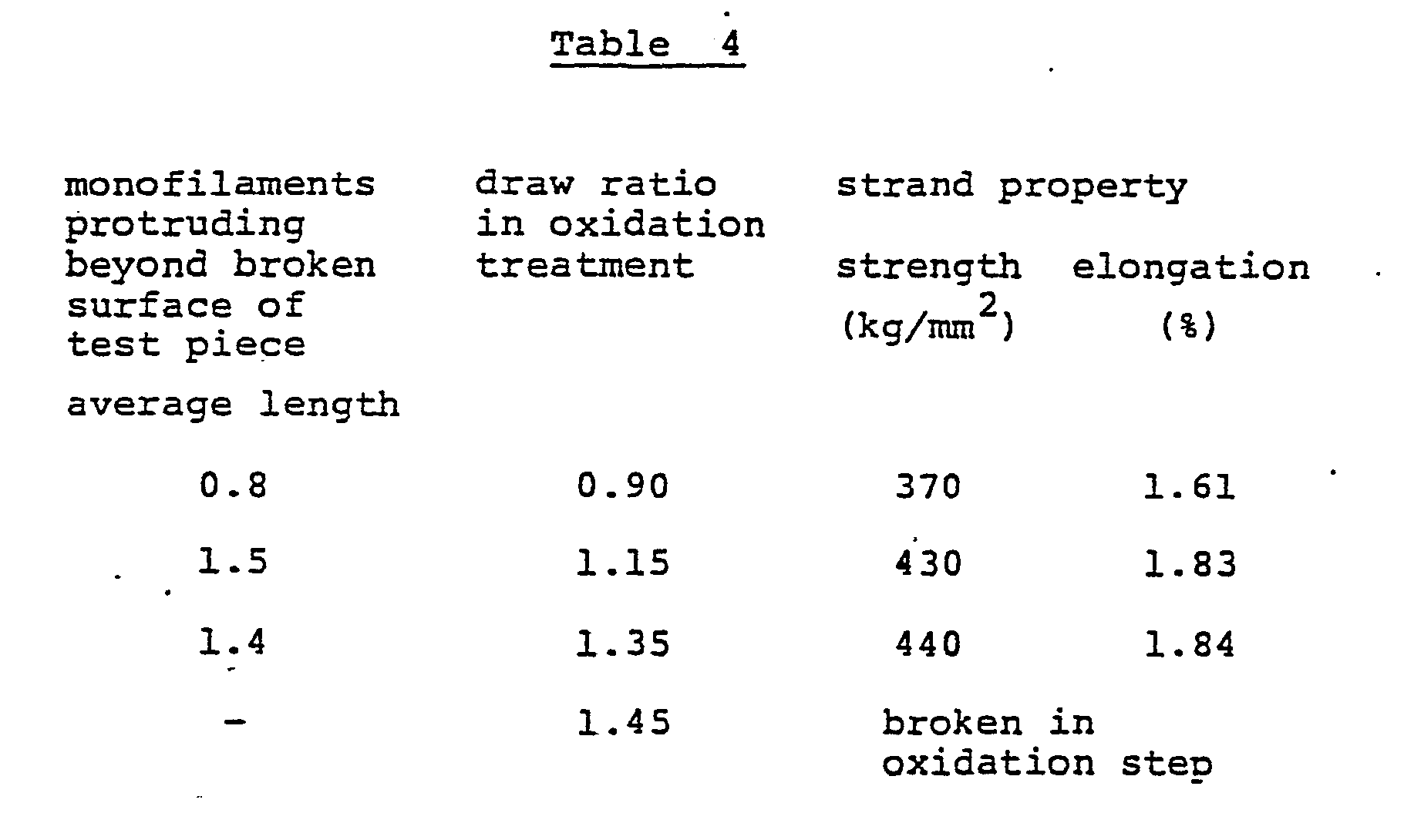
- Using the same spinneret as in Example 1, the same polymer solution as in Example 1 was discharged into an aqueous DMSO solution having 50% for the concentration and maintained at 50° C. Taking-up was operated at the coagulation take-up speed of 4 m/min, followed by same treatments as in Example 1 such as washing with water, hot-water drawing, silicone-oil finishing, drying and densifying, and steam drawing, to obtain an acrylic fiber bundle having the monofilament fineness of 0.5 d and the total denier of 6,000 D. The coagulation tension was 150 mg/filament.
- The above prepared fiber bundle was found to have 1.6% for the iodine adsorption level and 1.4 µ for the skin layer thickness.
- The acrylic fiber bundle was subjected to oxidation and carbonization in same manners as in Example 1 except that no twisting was applied to the fiber bundle and that the maximum carbonization temperature was raised to 1,400° C, to obtain carbon fibers, of which the average monofilament tensile strength was 570 kg/mm2, the average monofilament tensile elongation being 1.9%, the strand tensile strength being 620 kg/mm2, the elongation being 2.2%. Monofilaments having a monofilament strength below 300 kg/mm2 inclusive were contained at a ratio of 4%.
- By observing the broken surface of the strand, the average length of protruding portions of carbon fiber ends was determined to be 10.5 p, the ratio of which to the average carbon fiber monofilament diameter, 4.1 u, is about 2.6. The number of fiber ends protruding a length more than 5 times inclusive the diameter of the carbon fiber was about 30% of the total number of fibers.
- From the carbon fiber obtained above, test pieces of a composite material were prepared using the same matrix resin as in Example 1, and determinations were made of the interlayer shear strength and the tensile strength of the composite material, which were 2 2 8.3 kg/mm2 and 300 kg/mm , respectively.
- The starting filament with a level of adhered silicone oil finish of 0.19% by weight, obtained in Example 3, was imparted a twist of 15 T/m and then converted into an oxidized fiber having a moisture regain of 7.5% by weight by heating the twisted filament in air of 240 to 260° C at a draw ratio of 1.00.
- Next, a carbon fiber was obtained by carbonizing the above oxidized fiber in a nitrogen atmosphere having a maximum temperature of 1,300° C under conditions in which the rates of temperature rise in the temperature ranges of 300 to 700° C and 1,000 to 1,200° C were both 1,000° C/min. The produced carbon fiber had an average monofilament tensile strength of 330 kg/mm2, an average monofilament tensile elongation of 1.34%, a strand tensile strength of 390 kg/mm2, a Young's modulus of elasticity of 23.8 ton/mm2 and an elongation of 1.63%. On the other hand, the proportion of the monofilaments having a monofilament strength of not higher than 300 kg/mm2 was 36%.
- Then the broken surface of the strand was observed and its photograph was taken. The photograph of Fig. 2 was obtained.
- The average length of the protruding portions of the carbon fiber ends was measured from the photograph of Fig. 2, and it was 5.7 p. Its ratio to the average diameter of the carbon fiber was 0.88. Furthermore, the above carbon fiber was measured for a small angle X-ray diffraction intensity at an angle of 1°. It was 1,270 count/sec.
- In the same manner as in Example 1, a composite material test piece was prepared from the above carbon fiber and an epoxy resin, and measured for interlayer shear strength and tensile elongation. The results were 8.8 kg/mm2 and 150 kg/mm2, respectively.
- A spinning dope having a polymer concentration of 19.5% by weight and a temperature of 65° C was prepared by dissolving a copolymer consisting of 99.7 mol % of acrylonitrile (AN) and 0.3 mol % of acrylic acid in dimethyl sulfoxide (DMSO), and this dope was discharged into a coagulation bath containing a 55-% aqueous DMSO solution kept at nearly the same temperature (65° C) at an actual draft ratio of 3.5.
- The spinneret used had a hole diameter of 0.06 mm and a hole number of 1,500.
- The coagulate filament was washed with water, drawn in hot water and then drawn at a draw ratio of 4.5 so that the wet filament could have a moisture regain of about 200% by weight. Then 2% by weight of an organic oil finish, stearyl alcohol/ethylene oxide (20 mol) adduct, was applied to the filament in place of the silicone oil finish, and then filament was dried and densified around a heating drum having a surface temperature of 130° C. The produced dry fiber bundle was drawn at a ratio of 2.8 in pressured steam of a pressure of 4 kg/cm2 and dried again to obtain a fiber bundle having a monofilament fineness of 1 d and a total denier of 3,000 D.
- Table 5 shows the properties and iodine adsorption level of the produced fiber bundle, the skin layer thickness of an iodine-containing filament and the quality of a carbon fiber bundle obtained from the above-produced fiber bundle.

- The fiber bundle thus produced was oxidized by heating it for about 40 minutes at a tension of 0.2 g/d in a three-stage hot air circulation heating furnace maintained at temperatures of 230° C, 240° C and 250° C, and then carbonized for 5 minutes in a nitrogen atmosphere by raising the temperature from 300° C to 1,250° C at a rate of temperature rise of 800° C/min.
- The properties of a resin-impregnated strand of the produced carbon fiber were measured according to JIS-R-7601.
- The results were shown in Table 5.
- Moreover, the broken surface of a test piece used in the strand tensile test was observed with an electron microscope. As a result, it was found that the number of the monofilaments protruding beyond the broken surface by a length which is at least equal to the monofilament diameter was only about 5% based on the total number of the monofilaments.
- Using the same-polymer solution, spinneret and coagulation bath as in Example 1, spinning was operated at the coagulation speed of 20 m/min and same treatments as in Example 1 such as washing with water, hot-water drawing, finishing with silicone oil, drying and densifying, and steam drawing were operated, to-obtain an acrylic fiber bundle having 0.8 d and 4,800 D respectively for the monofilament fineness and the total denier. The tension in the coagulation step was so high as to be 290 mg/filament.
- The above prepared acrylic fibers were found to have 3.5% for the iodine adsorption level and 2.8 p for the skin layer thickness.
- In manners identical with those in Example 1 except that the oxidation time was enough long to obtain the moisture regain of 7.3%, the acrulic fiber bundle was subjected to oxidation and carbonization to obtain carbon fibers, of which the average monofilament tensile strength was 390 kg/mm2, the average monofilament tensile elongation being 1.5%, the strand tensile strength being 440 kg/mm2, the elongation being 1.79%.
- As a result of an observation of the broken surface of the strand, the average length of protruding portions of carbon fiber ends was found to be 4.3 µ, the ratio of which to the average carbon fiber monofilament diameter, 5.4 µ, is about 0.8. Further, the number of fiber ends protruding a length exceeding 5 times inclusive the diameter of-the carbon fibers was about 7% of the total number of fibers.
- From the carbon fiber obtained above, test pieces of a composite material were prepared using the same matrix resin as in Example 1, and determinations were made of the interlayer shear strength and the tensile strength of the composite material samples, which were 9.7 kg/mm2 and 205 kg/mm2, respectively.
Claims (9)
Priority Applications (1)
| Application Number | Priority Date | Filing Date | Title |
|---|---|---|---|
| AT83105414T ATE49614T1 (en) | 1982-06-09 | 1983-06-01 | HIGH TENSILE, HIGH ELONGATION CARBON FIBER BUNDLE AND METHOD FOR PRODUCTION THEREOF. |
Applications Claiming Priority (2)
| Application Number | Priority Date | Filing Date | Title |
|---|---|---|---|
| JP57097756A JPS58214534A (en) | 1982-06-09 | 1982-06-09 | Carbon fiber bundle having high strength and elongation and production thereof |
| JP97756/82 | 1982-06-09 |
Publications (3)
| Publication Number | Publication Date |
|---|---|
| EP0100410A2 true EP0100410A2 (en) | 1984-02-15 |
| EP0100410A3 EP0100410A3 (en) | 1987-03-25 |
| EP0100410B1 EP0100410B1 (en) | 1990-01-17 |
Family
ID=14200719
Family Applications (1)
| Application Number | Title | Priority Date | Filing Date |
|---|---|---|---|
| EP83105414A Expired - Lifetime EP0100410B1 (en) | 1982-06-09 | 1983-06-01 | High strength and high elongation carbon fiber bundle and process for producing the same |
Country Status (4)
| Country | Link |
|---|---|
| EP (1) | EP0100410B1 (en) |
| JP (1) | JPS58214534A (en) |
| AT (1) | ATE49614T1 (en) |
| DE (1) | DE3381116D1 (en) |
Cited By (5)
| Publication number | Priority date | Publication date | Assignee | Title |
|---|---|---|---|---|
| EP0279687A2 (en) * | 1987-02-20 | 1988-08-24 | Toray Industries, Inc. | Graphite fiber |
| EP0374925A2 (en) * | 1988-12-22 | 1990-06-27 | Toho Rayon Co., Ltd. | High density graphite fiber and method of manufacture thereof |
| EP0843033A1 (en) † | 1996-05-24 | 1998-05-20 | Toray Industries, Inc. | Carbon fiber, acrylic fiber, and method of manufacturing them |
| US6208856B1 (en) | 1997-12-08 | 2001-03-27 | Telefonaktiebolaget L M Ericsson | Method for maintaining service nodes in a telecommunications network |
| DE102021115851A1 (en) | 2021-06-18 | 2022-12-22 | Rolls-Royce Deutschland Ltd & Co Kg | circuit board |
Families Citing this family (1)
| Publication number | Priority date | Publication date | Assignee | Title |
|---|---|---|---|---|
| JPS59106521A (en) * | 1982-12-08 | 1984-06-20 | Toray Ind Inc | Production of acrylic carbon yarn having improved physical properties |
Citations (4)
| Publication number | Priority date | Publication date | Assignee | Title |
|---|---|---|---|---|
| FR1501286A (en) * | 1965-11-16 | 1967-11-10 | Nat Res Dev | Process improvements for the production of high mechanical strength carbon fibers |
| FR1539755A (en) * | 1966-07-08 | 1968-09-20 | Nat Res Dev | Process for the manufacture of carbon fiber fabrics from polymeric fibrous material |
| US3923950A (en) * | 1971-11-18 | 1975-12-02 | Celanese Corp | Production of stabilized acrylic fibers and films |
| US4009248A (en) * | 1975-04-04 | 1977-02-22 | Japan Exlan Company Limited | Process for producing carbon fibers |
Family Cites Families (4)
| Publication number | Priority date | Publication date | Assignee | Title |
|---|---|---|---|---|
| JPS5125487B2 (en) * | 1973-09-08 | 1976-07-31 | ||
| JPS5725418A (en) * | 1980-07-16 | 1982-02-10 | Mitsubishi Rayon Co Ltd | Preparation of low-density carbon fiber |
| JPS5725419A (en) * | 1980-07-16 | 1982-02-10 | Mitsubishi Rayon Co Ltd | Preparation of carbon fiber |
| JPS5742926A (en) * | 1980-08-22 | 1982-03-10 | Mitsubishi Rayon Co Ltd | Continuous production of carbon fiber |
-
1982
- 1982-06-09 JP JP57097756A patent/JPS58214534A/en active Granted
-
1983
- 1983-06-01 EP EP83105414A patent/EP0100410B1/en not_active Expired - Lifetime
- 1983-06-01 DE DE8383105414T patent/DE3381116D1/en not_active Expired - Fee Related
- 1983-06-01 AT AT83105414T patent/ATE49614T1/en not_active IP Right Cessation
Patent Citations (4)
| Publication number | Priority date | Publication date | Assignee | Title |
|---|---|---|---|---|
| FR1501286A (en) * | 1965-11-16 | 1967-11-10 | Nat Res Dev | Process improvements for the production of high mechanical strength carbon fibers |
| FR1539755A (en) * | 1966-07-08 | 1968-09-20 | Nat Res Dev | Process for the manufacture of carbon fiber fabrics from polymeric fibrous material |
| US3923950A (en) * | 1971-11-18 | 1975-12-02 | Celanese Corp | Production of stabilized acrylic fibers and films |
| US4009248A (en) * | 1975-04-04 | 1977-02-22 | Japan Exlan Company Limited | Process for producing carbon fibers |
Cited By (8)
| Publication number | Priority date | Publication date | Assignee | Title |
|---|---|---|---|---|
| EP0279687A2 (en) * | 1987-02-20 | 1988-08-24 | Toray Industries, Inc. | Graphite fiber |
| EP0279687A3 (en) * | 1987-02-20 | 1991-04-03 | Toray Industries, Inc. | Graphite fiber |
| EP0374925A2 (en) * | 1988-12-22 | 1990-06-27 | Toho Rayon Co., Ltd. | High density graphite fiber and method of manufacture thereof |
| EP0374925A3 (en) * | 1988-12-22 | 1991-09-25 | Toho Rayon Co., Ltd. | High density graphite fiber and method of manufacture thereof |
| EP0843033A1 (en) † | 1996-05-24 | 1998-05-20 | Toray Industries, Inc. | Carbon fiber, acrylic fiber, and method of manufacturing them |
| EP0843033B2 (en) † | 1996-05-24 | 2007-02-28 | Toray Industries, Inc. | Carbon fiber, acrylic fiber, and method of manufacturing them |
| US6208856B1 (en) | 1997-12-08 | 2001-03-27 | Telefonaktiebolaget L M Ericsson | Method for maintaining service nodes in a telecommunications network |
| DE102021115851A1 (en) | 2021-06-18 | 2022-12-22 | Rolls-Royce Deutschland Ltd & Co Kg | circuit board |
Also Published As
| Publication number | Publication date |
|---|---|
| DE3381116D1 (en) | 1990-02-22 |
| EP0100410B1 (en) | 1990-01-17 |
| JPH0329889B2 (en) | 1991-04-25 |
| EP0100410A3 (en) | 1987-03-25 |
| ATE49614T1 (en) | 1990-02-15 |
| JPS58214534A (en) | 1983-12-13 |
Similar Documents
| Publication | Publication Date | Title |
|---|---|---|
| TWI396785B (en) | Acrylonitrile swollen yarn for carbon fiber, precursor fiber bundle, flameproof fiber bundle, carbon fibre bundle and manufacturing method thereof | |
| JPH11241230A (en) | Carbon fiber, precursor fiber for carbon fiber, composite material and production of carbon fiber | |
| EP0835953B1 (en) | A precursor fibre bundle for production of a carbon fibre bundle, a carbon fibre bundle, and a process for producing thereof | |
| EP0355764A2 (en) | Improvements in the formation of melt-spun acrylic fibers | |
| JP2006299439A (en) | Carbon fiber, method for producing the same, acrylonitrile precursor fiber and method for producing the same | |
| EP0355762A2 (en) | Improvements in the formation of melt-spun acrylic fibers | |
| CN112368432A (en) | Carbon fiber and method for producing same | |
| EP0223199A2 (en) | Process for producing high-strenght, high-modulus carbon fibers | |
| EP0100410B1 (en) | High strength and high elongation carbon fiber bundle and process for producing the same | |
| US3841079A (en) | Carbon filaments capable of substantial crack diversion during fracture | |
| JP2004211240A (en) | Carbon fiber, acrylonitrile-based precursor fiber for the same, and method for producing the carbon fiber and the precursor fiber | |
| US5066433A (en) | Method of manufacturing carbon fiber using preliminary stretch | |
| JP4305081B2 (en) | Oil for carbon fiber production and method for producing carbon fiber | |
| JPS6052206B2 (en) | Method for manufacturing acrylic carbon fiber | |
| JPH086210B2 (en) | High-strength and high-modulus carbon fiber and method for producing the same | |
| JP2004003043A (en) | Flameproof fiber material, carbon fiber material, graphite fiber material and method for producing the same | |
| CN113597484B (en) | Carbon fiber bundle and method for producing same | |
| GB2130188A (en) | Process for producing carbon fiber or graphite fiber | |
| US3846833A (en) | Acrylic filaments which are particularly suited for thermal conversion to carbon filaments | |
| WO2023140212A1 (en) | Carbon fiber bundle | |
| JP6359860B2 (en) | Carbon fiber precursor fiber and method for producing carbon fiber precursor fiber | |
| JP2001248025A (en) | Method for producing carbon fiber | |
| JPH0329890B2 (en) | ||
| JP2000096353A (en) | Production of carbon fiber | |
| EP0329128B1 (en) | Novel method of manufacturing carbon fiber, or precursor fiber therefor, using preliminary stretch |
Legal Events
| Date | Code | Title | Description |
|---|---|---|---|
| PUAI | Public reference made under article 153(3) epc to a published international application that has entered the european phase |
Free format text: ORIGINAL CODE: 0009012 |
|
| AK | Designated contracting states |
Designated state(s): AT BE CH DE FR GB IT LI LU NL SE |
|
| 17P | Request for examination filed |
Effective date: 19840220 |
|
| PUAL | Search report despatched |
Free format text: ORIGINAL CODE: 0009013 |
|
| AK | Designated contracting states |
Kind code of ref document: A3 Designated state(s): AT BE CH DE FR GB IT LI LU NL SE |
|
| 17Q | First examination report despatched |
Effective date: 19871022 |
|
| ITF | It: translation for a ep patent filed |
Owner name: INTERPATENT ST.TECN. BREV. |
|
| GRAA | (expected) grant |
Free format text: ORIGINAL CODE: 0009210 |
|
| AK | Designated contracting states |
Kind code of ref document: B1 Designated state(s): AT BE CH DE FR GB IT LI LU NL SE |
|
| PG25 | Lapsed in a contracting state [announced via postgrant information from national office to epo] |
Ref country code: SE Effective date: 19900117 Ref country code: LI Effective date: 19900117 Ref country code: CH Effective date: 19900117 Ref country code: AT Effective date: 19900117 |
|
| REF | Corresponds to: |
Ref document number: 49614 Country of ref document: AT Date of ref document: 19900215 Kind code of ref document: T |
|
| REF | Corresponds to: |
Ref document number: 3381116 Country of ref document: DE Date of ref document: 19900222 |
|
| REG | Reference to a national code |
Ref country code: CH Ref legal event code: PL |
|
| ET | Fr: translation filed | ||
| PGFP | Annual fee paid to national office [announced via postgrant information from national office to epo] |
Ref country code: SE Payment date: 19900615 Year of fee payment: 8 |
|
| PG25 | Lapsed in a contracting state [announced via postgrant information from national office to epo] |
Ref country code: LU Free format text: LAPSE BECAUSE OF NON-PAYMENT OF DUE FEES Effective date: 19900630 |
|
| PGFP | Annual fee paid to national office [announced via postgrant information from national office to epo] |
Ref country code: BE Payment date: 19900709 Year of fee payment: 8 |
|
| PGFP | Annual fee paid to national office [announced via postgrant information from national office to epo] |
Ref country code: LU Payment date: 19900717 Year of fee payment: 8 |
|
| PLBE | No opposition filed within time limit |
Free format text: ORIGINAL CODE: 0009261 |
|
| STAA | Information on the status of an ep patent application or granted ep patent |
Free format text: STATUS: NO OPPOSITION FILED WITHIN TIME LIMIT |
|
| 26N | No opposition filed | ||
| ITTA | It: last paid annual fee | ||
| PG25 | Lapsed in a contracting state [announced via postgrant information from national office to epo] |
Ref country code: BE Effective date: 19910630 |
|
| BERE | Be: lapsed |
Owner name: TORAY INDUSTRIES INC. Effective date: 19910630 |
|
| PGFP | Annual fee paid to national office [announced via postgrant information from national office to epo] |
Ref country code: NL Payment date: 20000629 Year of fee payment: 18 |
|
| PGFP | Annual fee paid to national office [announced via postgrant information from national office to epo] |
Ref country code: DE Payment date: 20010528 Year of fee payment: 19 |
|
| PGFP | Annual fee paid to national office [announced via postgrant information from national office to epo] |
Ref country code: GB Payment date: 20010530 Year of fee payment: 19 |
|
| PG25 | Lapsed in a contracting state [announced via postgrant information from national office to epo] |
Ref country code: NL Free format text: LAPSE BECAUSE OF NON-PAYMENT OF DUE FEES Effective date: 20020101 |
|
| REG | Reference to a national code |
Ref country code: GB Ref legal event code: IF02 |
|
| NLV4 | Nl: lapsed or anulled due to non-payment of the annual fee |
Effective date: 20020101 |
|
| PG25 | Lapsed in a contracting state [announced via postgrant information from national office to epo] |
Ref country code: GB Free format text: LAPSE BECAUSE OF NON-PAYMENT OF DUE FEES Effective date: 20020601 |
|
| PGFP | Annual fee paid to national office [announced via postgrant information from national office to epo] |
Ref country code: FR Payment date: 20020610 Year of fee payment: 20 |
|
| PG25 | Lapsed in a contracting state [announced via postgrant information from national office to epo] |
Ref country code: DE Free format text: LAPSE BECAUSE OF NON-PAYMENT OF DUE FEES Effective date: 20030101 |
|
| GBPC | Gb: european patent ceased through non-payment of renewal fee |
Effective date: 20020601 |