EP0100219A2 - Drehbare Verbindung - Google Patents
Drehbare Verbindung Download PDFInfo
- Publication number
- EP0100219A2 EP0100219A2 EP83304267A EP83304267A EP0100219A2 EP 0100219 A2 EP0100219 A2 EP 0100219A2 EP 83304267 A EP83304267 A EP 83304267A EP 83304267 A EP83304267 A EP 83304267A EP 0100219 A2 EP0100219 A2 EP 0100219A2
- Authority
- EP
- European Patent Office
- Prior art keywords
- sealing
- retaining
- chamber
- rotary joint
- annular
- Prior art date
- Legal status (The legal status is an assumption and is not a legal conclusion. Google has not performed a legal analysis and makes no representation as to the accuracy of the status listed.)
- Granted
Links
Images

Classifications
-
- F—MECHANICAL ENGINEERING; LIGHTING; HEATING; WEAPONS; BLASTING
- F16—ENGINEERING ELEMENTS AND UNITS; GENERAL MEASURES FOR PRODUCING AND MAINTAINING EFFECTIVE FUNCTIONING OF MACHINES OR INSTALLATIONS; THERMAL INSULATION IN GENERAL
- F16L—PIPES; JOINTS OR FITTINGS FOR PIPES; SUPPORTS FOR PIPES, CABLES OR PROTECTIVE TUBING; MEANS FOR THERMAL INSULATION IN GENERAL
- F16L27/00—Adjustable joints; Joints allowing movement
- F16L27/08—Adjustable joints; Joints allowing movement allowing adjustment or movement only about the axis of one pipe
- F16L27/0804—Adjustable joints; Joints allowing movement allowing adjustment or movement only about the axis of one pipe the fluid passing axially from one joint element to another
- F16L27/0808—Adjustable joints; Joints allowing movement allowing adjustment or movement only about the axis of one pipe the fluid passing axially from one joint element to another the joint elements extending coaxially for some distance from their point of separation
-
- F—MECHANICAL ENGINEERING; LIGHTING; HEATING; WEAPONS; BLASTING
- F16—ENGINEERING ELEMENTS AND UNITS; GENERAL MEASURES FOR PRODUCING AND MAINTAINING EFFECTIVE FUNCTIONING OF MACHINES OR INSTALLATIONS; THERMAL INSULATION IN GENERAL
- F16L—PIPES; JOINTS OR FITTINGS FOR PIPES; SUPPORTS FOR PIPES, CABLES OR PROTECTIVE TUBING; MEANS FOR THERMAL INSULATION IN GENERAL
- F16L27/00—Adjustable joints; Joints allowing movement
- F16L27/08—Adjustable joints; Joints allowing movement allowing adjustment or movement only about the axis of one pipe
- F16L27/0849—Adjustable joints; Joints allowing movement allowing adjustment or movement only about the axis of one pipe the fluid being turned through an angle when passing from one joint element to another
Definitions
- This invention relates to a rotary joint which is particularly useful for deep-sea diving suits and similar apparatus.
- U.S. Patent 3,759,550 to Peress discloses a flexible joint having an annular, partially spherical, male member movably housed within an annular, partially spherical female member.
- the chamber formed between the male and female members is filled with a suitable fluid.
- Sealing means are provided on the female member wall.
- a rotary joint a plurality of which can be used to form a flexion-extension joint, which flexion-extension joint would be particularly useful in deep-sea diving, and in which rotational friction of each rotary joint would not be substantially increased with large increases in external pressure, which would maintain a good seal despite such large increases in pressure, and which is relatively simple to assemble.
- the invention provides a rotary joint comprising a sealing member having a sealing end with an annular axially facing, sealing surface portion; a retaining member having a circular retaining end concentric with the sealing surface portion of said sealing member; a central member disposed axially between said sealing member and retaining member, and having a circular first end dimensioned and axially slidably mounted on the retaining end of said retaining member so as to define a first variable volume chamber therebetween; a second end with an annular bearing member concentric with, and normally rotatably abutting the sealing surface portion, so as to define an annular side wall of a second chamber between the second end and the sealing end of said sealing member, which second chamber is interconnected with the first chamber.
- a sealing member has a sealing end with concentric, inner and outer sealing surface portions facing in the same axial direction, and the first end of the central member is annular, and the second end of the central member has inner and outer axially extending annular bearing members, each concentric with, and normally rotatably abutting a corresponding one of the sealing surface portions,-so as to define annular side walls of the second chamber.
- the central member has a first inner surface defining a wall of the first chamber and axially facing the retaining end of the retaining member, and a second inner surface defining a wall of the second chamber and axially facing the sealing surface of the sealing member.
- the total transverse area of the first inner surface is at least as great as the total transverse area of the second inner surface. Most preferably, those total transverse areas are equal.
- Resilient means may be additionally provided, which extend between the retaining member and the sealing member, for urging the bearing members against respective sealing portions.
- first and second chambers are interconnected by means of an opening through the central member.
- the sealing surface portions of the sealing member preferably lie in a common transverse plane, the bearing members being arranged to extend substantially perpendicular from the respective sealing portions.
- first and second chambers Of the possible relative average diameters of the first and second chambers, it is preferred that they have the same average diameter.
- a rotary joint 2 which connects cylindrical tubes 4 and 6, each of which has an annular support portion 3 and 5 respectively for the rotary joint 2.
- Annular portion 5 can be replaced with an annular flange 7 (shown in broken lines) if it is desired to connect the joint to a flat surface.
- the rotary joint 2 has a sealing member 8 with a sealing end 10'extending between and supporting inner and outer annular sealing surface portions 11 and 12 respectively.
- the sealing surface portions 11 and 12 face in the same axial direction and lie in a common transverse plane, that is, their upper surfaces as is shown in Figures 1 and 2 lie in the same transverse plane.
- the sealing member 8 has an extension 14 threaded on its inside so as to mate with threaded portion 16 of support 3.
- An annular sealing ring 17 is provided between support 3 and sealing member 8 so as to prevent water leakage therebetween.
- the support member 8 also has a second annular threaded portion 18, the threads of which mate with threaded portion 20 of collar 60.
- a retaining member 22 is provided which is axially spaced from sealing member 8.
- the retaining member 22 is provided with an annular retaining end 23, the retaining end 23 being that portion adjacent the annular recess 24 in retaining member 22, which retains an end of a central member 30.
- the annular end 23 is concentric with the sealing surface portions 11 and 12.
- the retaining member 22 is also provided with an outwardly threaded portion 26 which mates with a threaded portion 28 of the support 5.
- An annular sealing ring 29 is provided between the support 5 and sealing member 22 to prevent water leakage therepast.
- the central member 30 is disposed axially between the sealing member 8 and retaining member 22.
- the central member 30 is provided with an annular first end 32 which is axially slidably mounted within the recess 24 of the retaining end 23 by means of a sealing 0-ring 34 extending therebetween, so as to define a first variable volume chamber 40 between the first end 32 of central member 30 and the retaining end 23 of retaining member 22.
- the first end 32 of the central member 30 has a first inner surface which is the combination of annular surface portions 36 and 38, this inner surface axially facing the retaining end 23 of the retaining member 22.
- the central member 30 also has a second end 41 with a second inner surface 42 axially facing the sealing end 10.
- the total transverse area of the first inner surface (that is, the total transverse area of surface sections 36 and 38) is equal to the total transverse area of the second inner surface 42.
- the central member 30 also has inner and outer axially extending annular bearing members, 44 and 46 respectively.
- Each of the bearing members 44 and 46 is concentric with, and normally rotatably abuts a corresponding one of the sealing surface portions 11 and 12 respectively.
- the bearing members 44 and 46 define annular side walls of a second chamber 48 between the first end 41 of the central member 30 and the sealing end 10 of the sealing member 8.
- the second chamber 48 is interconnected with the first chamber 40 by means of an annular opening 50 through the central member.
- a plurality of springs 52 are provided within the first chamber 40, which springs extend between the retaining end 23 of the retaining member 22, and the surface portion 38 of the central member 30, so as to urge the bearing members 44 and 46 against respective sealing surface portions 11 and 12.
- a hollow cylindrical housing 54 is provided for each spring 52 in order to help retain the shape of that spring 52.
- the annular portion 18 of sealing member 8 is provided with two annular radially extending bearing , rings 56, which both abut the retaining member 22 but do not abut it with such force that water under pressure cannot pass therebetween and into a third chamber 49.
- the outer collar 60 is also provided with an annular bearing ring 58, and felt wiper 62, which respectively abut retaining member 22 and support 5, but again allow water under pressure to pass therebetween.
- a bore 64 extends between the chamber 48 and the exterior of the rotary joint.
- the rotary joint as described is typically constructed from steel, the bearing members 44 and 46 preferably being of stainless steel.
- the sealing surface portions 11 and 12, and annular sealing rings 56 and 58 can be made of a deformable low friction material, for example, an epoxy bonded tetrafluoroethylene plastic, such as that sold under the trade mark TEFLON.
- the joint can be assembled by first screwing on portion 14 of sealing member 8 onto the threaded portion 16 of support portion 3.
- the central member 30, springs 52 and supports 54 can then be positioned between the sealing member 8 and the support member 22 with sufficient force being applied to retaining member 22 so that collar 60 can be screwed onto threaded portion 18 of sealing member 8.
- the threaded portion 26 of retaining member 22 may then be screwed onto the threaded portion 28 of support member 5.
- the chambers 40, 48 and annular opening 50 can then be filled with oil through oil passage 64.
- Oil passage 64 can then be sealed in any suitable manner, such as with a threaded plug.
- one rotary joint 2 is as follows. When the joint is submerged in water, chamber 49 will fill with water flowing past wiper 62 and bearing surfaces 58 and 56. When the joint is subjected to high external pressure, tubes 4 and 6 and respective support portions 3 and 5 will tend to telescope inward to compress the joint 2. This force of compression will be translated into a fluid pressure in chambers 40, 48 and annular hole 50. As a result of such fluid pressure, a force will be generated in chamber 40 between the retaining surface 23 of retaining member 22, and the first end 32 of central member 30. This force will vary directly with the total surface area of the first surface of first end 32 which is facing the retaining end 23 (again, this being the total surface area of surface portions 36 and 38).
- the springs 52 ensure that a constant pressure is maintained on bearing members 44 and 46 against their respective slightly deformable sealing surface portions 11 and 12, respectively, so as to prevent water or oil from leaking therepast.
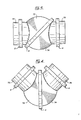
- a number of such joints 2 can be utilized to produce a flexion-extension joint in the manner shown in Figures 3 and 4.
- a first tubular portion 70 is connected through a joint 2 to a partially spherical portion 72, which is in turn connected through another joint 2 to another partially spherical tubular portion 74.
- This second partially spherical tubular portion 74 is connected through a third joint to a third tubular portion 76.
- a flexion-extension joint is created.
- tubular sections 70 and 76 When an internal force is applied to tubular sections 70 and 76, for example by flexing of a limb, sections 72 and 74 will rotate by means of their respective joints 2 interconnecting them with adjacent tubular portions 70 and 76 respectively, so as to bring their narrowest sections together at one point and their widest sections together at a point slightly less than 180° away, or any degree inbetween.
- Figure 4 which shows the joint bent at an angle of slightly less than 90°
- Blocks (not shown) must be provided on the two outermost joints 2 on two of the tubular portions, which will contact one another prior to the joint flexing to 90° and prevent further flexion. Should the joint reach 90°, it would of course lock up and could no longer be straightened.
- the pressure on bearing members 44 and 46 against respective sealing surface portions 11 and 12 would increase proportionately with increasing external pressure on the joint 2.
- the absolute value of this latter pressure at any given external pressure can of course be varied simply by varying the total transverse surface areas of the first surface and second surface of the central member 30 which are axially facing the retaining end 23 and sealing end 10 respectively.
- the total transverse surface area of the second surface 42 which is axially facing the sealing surface 10 can be made greater than the total transverse surface area of the first surface of central member 30 which is axially facing the retaining end 23.
- the first and second inner surfaces of the central member 30 could in fact be eliminated so that central member 30 is simply a hollow tube.
- such a configuration eliminates a convenient location for the springs 52.
- the bearing surfaces 44 and 46 need not be perpendicular to the common transverse plane which the sealing surface portions 11 and 12 lie, as is the situation disclosed in the drawings. However, such a configuration is preferred since it provides maximum pressure resistance of the joint.
Landscapes
- Engineering & Computer Science (AREA)
- General Engineering & Computer Science (AREA)
- Mechanical Engineering (AREA)
- Joints Allowing Movement (AREA)
- Hydraulic Clutches, Magnetic Clutches, Fluid Clutches, And Fluid Joints (AREA)
Applications Claiming Priority (2)
| Application Number | Priority Date | Filing Date | Title |
|---|---|---|---|
| CA407922 | 1982-07-23 | ||
| CA000407922A CA1171601A (en) | 1982-07-23 | 1982-07-23 | Rotary joint |
Publications (3)
| Publication Number | Publication Date |
|---|---|
| EP0100219A2 true EP0100219A2 (de) | 1984-02-08 |
| EP0100219A3 EP0100219A3 (en) | 1984-10-10 |
| EP0100219B1 EP0100219B1 (de) | 1988-06-08 |
Family
ID=4123276
Family Applications (1)
| Application Number | Title | Priority Date | Filing Date |
|---|---|---|---|
| EP19830304267 Expired EP0100219B1 (de) | 1982-07-23 | 1983-07-22 | Drehbare Verbindung |
Country Status (6)
| Country | Link |
|---|---|
| EP (1) | EP0100219B1 (de) |
| JP (1) | JPS5954885A (de) |
| AU (1) | AU1685383A (de) |
| CA (1) | CA1171601A (de) |
| DE (1) | DE3377005D1 (de) |
| NO (1) | NO156522C (de) |
Families Citing this family (1)
| Publication number | Priority date | Publication date | Assignee | Title |
|---|---|---|---|---|
| CA1296032C (en) * | 1987-09-04 | 1992-02-18 | R.T. Phil Nuytten | Pressure equalizing rotary joint |
Family Cites Families (8)
| Publication number | Priority date | Publication date | Assignee | Title |
|---|---|---|---|---|
| US1888026A (en) * | 1925-03-19 | 1932-11-15 | Ralph E Chapman | Balanced joint |
| US2557140A (en) * | 1948-12-23 | 1951-06-19 | Razdowitz Adolph | Rotary joint |
| US3057646A (en) * | 1959-12-23 | 1962-10-09 | Brumagim Ivan Stanley | Rotary seal with cooling means |
| GB1141403A (en) * | 1965-09-10 | 1969-01-29 | Litton Industries Inc | Sealed movable joints |
| GB1332902A (en) * | 1970-09-04 | 1973-10-10 | Peress J S | Flexible joint |
| US3754779A (en) * | 1970-09-04 | 1973-08-28 | J Peress | Flexible joints |
| JPS5340650B2 (de) * | 1974-01-31 | 1978-10-28 | ||
| GB1603163A (en) * | 1978-05-09 | 1981-11-18 | Anderson R H | Rotary joint |
-
1982
- 1982-07-23 CA CA000407922A patent/CA1171601A/en not_active Expired
-
1983
- 1983-07-14 AU AU16853/83A patent/AU1685383A/en not_active Abandoned
- 1983-07-20 NO NO832641A patent/NO156522C/no unknown
- 1983-07-22 EP EP19830304267 patent/EP0100219B1/de not_active Expired
- 1983-07-22 JP JP13295883A patent/JPS5954885A/ja active Pending
- 1983-07-22 DE DE8383304267T patent/DE3377005D1/de not_active Expired
Also Published As
| Publication number | Publication date |
|---|---|
| EP0100219B1 (de) | 1988-06-08 |
| EP0100219A3 (en) | 1984-10-10 |
| NO832641L (no) | 1984-01-24 |
| NO156522B (no) | 1987-06-29 |
| CA1171601A (en) | 1984-07-31 |
| DE3377005D1 (en) | 1988-07-14 |
| NO156522C (no) | 1987-10-07 |
| AU1685383A (en) | 1984-01-26 |
| JPS5954885A (ja) | 1984-03-29 |
Similar Documents
| Publication | Publication Date | Title |
|---|---|---|
| US4549753A (en) | Rotary joint | |
| US5133578A (en) | Flexible joint with non-diffusive barrier | |
| US3318335A (en) | Torsional pipe coupling | |
| US5048622A (en) | Hermetically sealed progressive cavity drive train for use in downhole drilling | |
| US5704838A (en) | Down-hole motor universal joint | |
| JPH01120416A (ja) | ジョイント | |
| SU1602403A3 (ru) | Соединение стальных труб | |
| US3499670A (en) | Flexible pressure-type joint for rigid tubing | |
| US3088759A (en) | Swivel pipe coupling having low friction seals | |
| GB2253462A (en) | Downhole drilling apparatus drive train | |
| US3933012A (en) | Torque absorber for submergible pumps | |
| US4103939A (en) | Multi passage flexible connector | |
| WO1995003471A1 (en) | Elastomeric joint and articulated coupling and progressive cavity device using the same | |
| JPH0718517B2 (ja) | たわみ継手 | |
| EP0100219A2 (de) | Drehbare Verbindung | |
| CN101427048A (zh) | 回转式阻尼器的破坏防止机构 | |
| JPH1182853A (ja) | 流体輸送管の外套管構造 | |
| EP0081812B1 (de) | Feuersichere Abdichtung für Drehverbindungen | |
| AU614765B2 (en) | Pressure equalizing rotary joint | |
| US6186476B1 (en) | Shut-off valve for pipes | |
| JPS62297587A (ja) | 可撓性継手手段 | |
| JP4164549B2 (ja) | 偏心軸継手構造とその偏心軸継手構造を備えた一軸偏心ねじポンプ | |
| US2907593A (en) | Unpacked ball and socket with spring-biased ball | |
| WO1980001309A1 (fr) | Joint universel creux | |
| US1096293A (en) | Universal joint. |
Legal Events
| Date | Code | Title | Description |
|---|---|---|---|
| PUAI | Public reference made under article 153(3) epc to a published international application that has entered the european phase |
Free format text: ORIGINAL CODE: 0009012 |
|
| AK | Designated contracting states |
Designated state(s): DE FR GB IT NL SE |
|
| PUAL | Search report despatched |
Free format text: ORIGINAL CODE: 0009013 |
|
| AK | Designated contracting states |
Designated state(s): DE FR GB IT NL SE |
|
| 17P | Request for examination filed |
Effective date: 19850404 |
|
| 17Q | First examination report despatched |
Effective date: 19860401 |
|
| RAP1 | Party data changed (applicant data changed or rights of an application transferred) |
Owner name: INTERNATIONAL HARD SUITS INC. |
|
| GRAA | (expected) grant |
Free format text: ORIGINAL CODE: 0009210 |
|
| AK | Designated contracting states |
Kind code of ref document: B1 Designated state(s): DE FR GB IT NL SE |
|
| ITF | It: translation for a ep patent filed | ||
| REF | Corresponds to: |
Ref document number: 3377005 Country of ref document: DE Date of ref document: 19880714 |
|
| ET | Fr: translation filed | ||
| PLBE | No opposition filed within time limit |
Free format text: ORIGINAL CODE: 0009261 |
|
| STAA | Information on the status of an ep patent application or granted ep patent |
Free format text: STATUS: NO OPPOSITION FILED WITHIN TIME LIMIT |
|
| 26N | No opposition filed | ||
| ITTA | It: last paid annual fee | ||
| PGFP | Annual fee paid to national office [announced via postgrant information from national office to epo] |
Ref country code: SE Payment date: 19910731 Year of fee payment: 9 Ref country code: NL Payment date: 19910731 Year of fee payment: 9 Ref country code: FR Payment date: 19910731 Year of fee payment: 9 |
|
| PGFP | Annual fee paid to national office [announced via postgrant information from national office to epo] |
Ref country code: GB Payment date: 19910801 Year of fee payment: 9 |
|
| PGFP | Annual fee paid to national office [announced via postgrant information from national office to epo] |
Ref country code: DE Payment date: 19910803 Year of fee payment: 9 |
|
| PG25 | Lapsed in a contracting state [announced via postgrant information from national office to epo] |
Ref country code: GB Effective date: 19920722 |
|
| PG25 | Lapsed in a contracting state [announced via postgrant information from national office to epo] |
Ref country code: SE Effective date: 19920723 |
|
| PG25 | Lapsed in a contracting state [announced via postgrant information from national office to epo] |
Ref country code: NL Effective date: 19930201 |
|
| NLV4 | Nl: lapsed or anulled due to non-payment of the annual fee | ||
| GBPC | Gb: european patent ceased through non-payment of renewal fee |
Effective date: 19920722 |
|
| PG25 | Lapsed in a contracting state [announced via postgrant information from national office to epo] |
Ref country code: FR Effective date: 19930331 |
|
| PG25 | Lapsed in a contracting state [announced via postgrant information from national office to epo] |
Ref country code: DE Effective date: 19930401 |
|
| REG | Reference to a national code |
Ref country code: FR Ref legal event code: ST |
|
| EUG | Se: european patent has lapsed |
Ref document number: 83304267.4 Effective date: 19930204 |