EP0099267A2 - Dekanterzentrifugen - Google Patents
Dekanterzentrifugen Download PDFInfo
- Publication number
- EP0099267A2 EP0099267A2 EP83304030A EP83304030A EP0099267A2 EP 0099267 A2 EP0099267 A2 EP 0099267A2 EP 83304030 A EP83304030 A EP 83304030A EP 83304030 A EP83304030 A EP 83304030A EP 0099267 A2 EP0099267 A2 EP 0099267A2
- Authority
- EP
- European Patent Office
- Prior art keywords
- bowl
- liquids
- conveyor
- gas
- solids
- Prior art date
- Legal status (The legal status is an assumption and is not a legal conclusion. Google has not performed a legal analysis and makes no representation as to the accuracy of the status listed.)
- Granted
Links
Images


Classifications
-
- B—PERFORMING OPERATIONS; TRANSPORTING
- B04—CENTRIFUGAL APPARATUS OR MACHINES FOR CARRYING-OUT PHYSICAL OR CHEMICAL PROCESSES
- B04B—CENTRIFUGES
- B04B1/00—Centrifuges with rotary bowls provided with solid jackets for separating predominantly liquid mixtures with or without solid particles
- B04B1/20—Centrifuges with rotary bowls provided with solid jackets for separating predominantly liquid mixtures with or without solid particles discharging solid particles from the bowl by a conveying screw coaxial with the bowl axis and rotating relatively to the bowl
-
- Y—GENERAL TAGGING OF NEW TECHNOLOGICAL DEVELOPMENTS; GENERAL TAGGING OF CROSS-SECTIONAL TECHNOLOGIES SPANNING OVER SEVERAL SECTIONS OF THE IPC; TECHNICAL SUBJECTS COVERED BY FORMER USPC CROSS-REFERENCE ART COLLECTIONS [XRACs] AND DIGESTS
- Y10—TECHNICAL SUBJECTS COVERED BY FORMER USPC
- Y10S—TECHNICAL SUBJECTS COVERED BY FORMER USPC CROSS-REFERENCE ART COLLECTIONS [XRACs] AND DIGESTS
- Y10S494/00—Imperforate bowl: centrifugal separators
- Y10S494/90—Imperforate bowl: centrifugal separators involving mixture containing one or more gases
Definitions
- the present invention relates to centrifuges of the decanting type.
- Decanting type centrifuges employ a main bowl which is adapted to be rotated about a horizontal or vertical axis and which contains a helical scroll conveyor which is arranged to rotate at a slightly different speed to the main bowl for scrolling separated solids to a solids discharge end of the bowl.
- the separated liquid phase(s) is normally discharged at the opposite end of the bowl.
- the bowl itself can be of two principle types, namely the solid bowl type and screen bowl type. In the latter type, the solids are caused to move over a perforated screen: portion of the bowl prior to their discharge from the bowl.
- Existing decanter centrifuges of both the solid and screen bowl types can function (a) to separate solid particles from a liquid where the solids have a larger specific gravity than the liquid, this being referred to as two-phase separation, (b) to separate into three .fractions solid particles in a mixture of two liquids where the solids have a larger specific gravity than both liquids and the liquids (one of which is immiscible) have differing specific gravities, this being referred to as three-phase separation or (c) to classify.solids, that is to split the solids so that particles above a selected size are discharged as solids and particles below that size are discharged with the liquid or liquids.
- the term "separate" when applied to solids and liquids includes also the classificiation function.
- An object of the present invention is to modify the design of both.solid and screen bowl decanters so that, in addition to separating the slurries of solids and liquid(s) as described above, such centrifuges can also separate gas or vapor fed to them with the slurry, including gas insulation in the liquid.
- gas as used hereinafter includes vapors.
- the gas isolating means can ocmprise a pair of annular plates carried by the conveyor hub for rotation therewith, the diameter of these plates being less than the inner surface of the scrolled solids and greater than the inner free surface of the liquid in the bowl.
- the input slurry is fed to the bowl interior via radially outwardly extended feed ports open beneath the liquid surface within the bowl.
- the annular disc at the liquid outlet end of the bowl can be obviated by the provision of floating weir plates which float on the liquid surface leaving the bowl through holes in the bowl end plate whereby to seal that end of the bowl against the egress of gas.
- the annular plate at the liquid outlet end of the bowl can be attached to the bowl trunnion instead of the conveyor if the liquid leaving that end of the bowl is first collected in a cylindrical chamber into which the latter annular plate is arranged to extend so that its periphery lies beneath the liquid surface therein.
- the latter annular plate can be fixed so as to be stationary relative to the bowl and to the conveyor.
- the gas isolation means can comprise a single annular plate carried by the frusto--eonical part of the conveyor hub, the gas volume being defined between the latter plate, the frusto-conical surface of the hub and the inner cylindrical surface of the liquid in the bowl.
- the slurry entering the bowl 10 is subjected to centrifugal forces as a result of the rotation of the bowl and the slurry separates into a solids phase and liquid phase.
- the surface of the liquid is indicated at 36, this level being determined by the radial position of a liquid outlet port(s) 38 in the end plate 40 of the bowl 10.
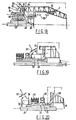
- Fig. 2 shows a conventional screen bowl decanter centrifuge for two-phase solid/liquid separation.
- the structure of this centrifuge is identical to that of the solid bowl centrifuge of Fig. 1 except that the bowl 42 includes a cylindrical screen portion 43 through which liquid and fine solids can pass to achieve additional drying and separation which may be required in certain circumstances.
- Those parts of the centrifuge which are identical to the centrifuge of Fig. 1 are given the same reference numbers.
- Fig. 3 shows the changes necessary to the liquid discharge end of either of the centrifuges of Fig. 1 and Fig. 2 when three-phase separation of solids and two liquids is required. Again, reference numerals corresponding to those of Figs. 1 and 2 are used where appropriate.
- the liquid 44 of lower specific gravity referred to as the light phase
- the liquid 46 of higher specific gravity referred to as the heavy phase
- the interface between the two liquid phases is marked 3?.
- the light and heavy phases 44, 46 are discharged into separate compartments 48, 50, respectively from where they are removed via respective outlets 52, 54.
- any free gas fed with the slurry to the centrifuge via the feed pipe 28 will, by virtue of its low specific gravity, be displaced by the 'G' forces on the other heavier constituents of the slurry and will flow inwards towards the axis of the centrifuge into the isolated volume for separate collection via sealed passages.
- the liquid around the -isolated volume is subjected to the high 'G' forces of rotation and hence to the high hydraulic pressures whilst its inner free surface 36 remains at or near atmospheric pressure.
- gas dissolved in the liquid will be freed out of solution, will form bubbles of low-specific gravity and will move rapidly through the inner free surface 36 to collect in the isolated gas volume.
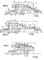
- Figs. 4 to 7 are concerned with solid and screen bowl decanter centrifuges of the type which separate two phases which are now to separate solid, liquid and gas phases.
- Fig. 4 shows the simplest arrangement in which two flat annular discs X and Y are fixed to and rotate with the conveyor hub 32, each disc being of an outside diameter D greater than the diameter L of the inner free surface 36.of the liquid and less than the diameter S of the inner surface of the scrolled solids 16.
- the slurry is introduced via radially extended feed ports 56. Gas thus separated flows through a gas port(s) 59 and along the path 61 shown. The latter flow can be induced if necessary by externally applied suction to collect only the gas and/or vapour fed with the slurry plus any gas released from solution in the liquid.
- Fig. 5 shows an alternative construction in which, in order to increase the isolated volume for gas separation, the annular ring X is replaced by floating weir plates 60 to cover the unsubmerged area of each liquid outlet 38 in the bowl.
- Each plate 60 is made of light or hollow material and is mounted in guides so as to float on the liquid surface, allowing just sufficient opening for liquid discharge and thus sealing the bowl liquid end plate 40 against the outflow of gas or vapour so that the sealed bowl end plate 40 forms part of the gas isolation volume 58.
- Allowing the separated liquid to flow over a lip 62 and into a cylindrical chamber 64 formed by an extension of the bowl 10 and containing an annular disc Z fixed to and rotating with the bowl trunnion 20 (all in place of the disc X), as shown in Fig. 6, increases the isolated volume and capacity to separate gas. It offers the added advantage of causing the liquid to flow radially outwards in a thin film 66, increasing the surface area per unit volume and separation of gas in solution and giving an effective design for maximum gas separation.
- the separated liquid either spills over the weir 68 or is skimmed from the surface of the cylindrical chamber by a skimmer pipe, paring disc or other known means 70.
- Gas ports 72 are provided in the conveyor hub and the end wall of the bowl.
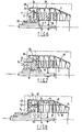
- FIG. 7 An alternative construction, shown in Fig. 7, uses the same bowl construction as that shown in Fig. 6 with the separated liquid flowing into the cylindrical chamber 64.
- a stationary annular disc W of diameter D larger than the inner free surface of the liquid in the cylindrical chamber 64, is attached to and supported by the gas outlet 74.
- the bowl end plate 40- has gas ports 76 permitting the separated gas to flow in the direction shown.
- Such a design may be used primarily to provide . maximum gas outlet area when large gas volumes are to be separated.
- Figs. 8 to 14 are concerned with solid and screen bowl decanter centrifuges of the type which separate three phases and which are now to separate solid/liquid/ liquid/gas phases.
- annular discs X and Y are applicable to this type of decanter also, as shown in Fig. 8, wherein the diameter D of the discs is greater than the diameter of the inner free surface 36 of the liquid with the lowest specific gravity.
- One annular disc may be positioned at X 1 or, for increased gas separation volume, at X 2 - In the latter case, a cylindrical sealing plate 78 is fitted to isolate the gas volume from the ingress of air through the heavy phase liquid outlet 54 if gas uncontaminated with air is required.
- Pipes 80 connect separated light phase liquid to the light phase compartment 48.
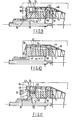
- FIG. 9 An alternative construction is shown in Fig. 9 wherein the annular discs X 1 and X 2 are replaced by floating weir plates 60, as in Fig. 5, to cover the unsubmerged area of each outlet port of the light phase liquid. Again a cylindrical plate 78 is fitted to isolate the gas volume from the ingress of air through the heavy phase liquid outlet 54.
- FIG. 10 A further alternative construction is shown in Fig. 10.
- the separated light phase liquid 44 flows from the bowl through radial outlet pipes 82 in the bowl wall.
- the separated heavy phase liquid 46 passes under the dividing plate 47 to the liquid compartment 50 and flows out of the outlet ports over the floating weir plates 60, which cover the unsubmerged portion of the outlet ports and thus seal the isolated gas volume.
- Figs. 11 and 12 shows a gas separation volume sealed by discs Y and Z and Figs. 13 and 14 showr a gas separation volume sealed by discs Y and W.
- the outside diameters of discs Z and W are greater than the diameter of the inner free surface of the liquid in the cylindrical compartments 64 and disc Y is as described previously.
- the annular disc Z is fixed to and rotates with the bowl trunnion 20, with the separated gas flowing through the gas ports 59 in the coveyor hub 32 and in the bowl end plate 40.
- Figs. 1 to 14 All of the decanting centrifuges described so far and shown in Figs. 1 to 14 are of the counter-current type, that is, during the separation process the solids and liquid(s) flow in opposite axial directions.
- the solids and liquid flow can be arranged to occur in the same axial direction during the separation process.
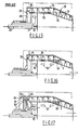
- a typical known con-current flow decanter of this type is shown in Fig. 15. Normally, con-current flow decanters perform a two-phase separation only. The present invention enables this to be extended to solids/liquid/gas separation.
- Fig. 16 uses one annular disc Y of diameter D greater than the diameter of the inner free surface of the liquid and less than the diameter of the inner surface of the scrolled solids.
- This disc together with the conveyor hub 32, extended feed ports 56 and a sealing plate 84 provide an isolated gas volume 58 (albeit relatively small) for gas separation with the separated gas-flowing through the gas ports 59 and from the decanter hub as shown. This is analagous to the arrangement shown in Fig. 4 except that the feed zone is no longer contained within the isolated gas volume.
- FIG. 18 A further and preferred alternative is shown in .
- Fig. 18 uses the same bowl construction as that shown in Fig. 17 with the separated liquid flowing into a cylindrical chamber 64.
- a stationary annular disc W is attached at and supported by the gas outlet 74.
- the gas separated in the solid/liquid separating zone flows as shown through pipes 88 fitted through the feed zone and holes 59 in the bowl end plate to discharge with the gas separated during liquid flow over the lip 62.
- a suction can be applied externally.
- impeller blades 90 within a stationary gas collecting chamber 94 fitted to the bowl trunnion 20 and rotating with it, will induce the required pressure reduction in the isolated gas volume 58.
- Impeller arrangements suitable for the various decanting centrifuge arrang- ments are shown in Figs. 19 and 20. Main pedestal bearings for the bowl trunnion are indicated at 98 and the drive pulley for the bowl trunnion is indicated at 94.
- This invention is considered to be particularly advantageous in decanter applications where gas, other than air, is involved.
- gas other than air
- chemical processes carried out under a gas "blanket” that require removal of the solids and/or liquid(s) from the blanket at the separation stage would use this type of centrifuge.
- Another application is that of processing oil and gas well drilling mud which requires classifying (i.e. the separation of drilled solids from the mud and fine additives) whilst simultaneously removing any gas that has contaminated the mud either during drilling or during its passage through the drilled hole.
Landscapes
- Centrifugal Separators (AREA)
Applications Claiming Priority (2)
| Application Number | Priority Date | Filing Date | Title |
|---|---|---|---|
| GB8220297 | 1982-07-13 | ||
| GB08220297A GB2123717B (en) | 1982-07-13 | 1982-07-13 | Improvements in decanting type centrifuges |
Publications (3)
| Publication Number | Publication Date |
|---|---|
| EP0099267A2 true EP0099267A2 (de) | 1984-01-25 |
| EP0099267A3 EP0099267A3 (en) | 1984-11-07 |
| EP0099267B1 EP0099267B1 (de) | 1990-03-07 |
Family
ID=10531643
Family Applications (1)
| Application Number | Title | Priority Date | Filing Date |
|---|---|---|---|
| EP83304030A Expired EP0099267B1 (de) | 1982-07-13 | 1983-07-12 | Dekanterzentrifugen |
Country Status (7)
| Country | Link |
|---|---|
| US (1) | US4443213A (de) |
| EP (1) | EP0099267B1 (de) |
| AU (1) | AU562368B2 (de) |
| DE (1) | DE3381284D1 (de) |
| GB (1) | GB2123717B (de) |
| IN (1) | IN171301B (de) |
| NO (1) | NO165578C (de) |
Cited By (4)
| Publication number | Priority date | Publication date | Assignee | Title |
|---|---|---|---|---|
| EP0173676A1 (de) * | 1984-08-30 | 1986-03-05 | VOEST-ALPINE Aktiengesellschaft | Zentrifuge für die Entwässerung und Trocknung vorentwässerter Schlämme |
| DE19948115A1 (de) * | 1999-10-06 | 2001-04-12 | Baker Hughes De Gmbh | Zentrifuge zur Trennung von Feststoff-Flüssigkeitsgemischen |
| WO2015187450A3 (en) * | 2014-06-05 | 2016-01-28 | Somerset Coal International | Fine particle coal, and systems, apparatuses, and methods for collecting and using the same |
| DE202022101838U1 (de) | 2022-04-06 | 2023-07-10 | Gea Westfalia Separator Group Gmbh | Vollmantel-Schneckenzentrifuge |
Families Citing this family (1)
| Publication number | Priority date | Publication date | Assignee | Title |
|---|---|---|---|---|
| US20130168317A1 (en) * | 2011-12-30 | 2013-07-04 | Vanderbeken Enterprises Ltd. Dba Drycake | Method and apparatus for removal of tars, resins, chars or volatiles from a liquid |
Family Cites Families (10)
| Publication number | Priority date | Publication date | Assignee | Title |
|---|---|---|---|---|
| US2228816A (en) * | 1939-01-05 | 1941-01-14 | Gen Electric | Apparatus for separating fluids |
| DE877575C (de) * | 1942-09-01 | 1953-05-26 | Bayerische Motoren Werke Ag | Zentrifuge zur Trennung von Gasen und Fluessigkeiten, insbesondere fuer schaeumende Fluessigkeiten |
| US2905379A (en) * | 1956-08-03 | 1959-09-22 | Const Guinard Soc | Solid jacket centrifugal separator |
| US3273789A (en) * | 1963-05-22 | 1966-09-20 | Bird Machine Co | Solid bowl centrifuge with air circulation control |
| FR1388992A (fr) * | 1964-01-03 | 1965-02-12 | Procédé d'extraction de l'huile contenue dans une pâte d'olives broyées et extracteur centrifuge perfectionné servant à la mise en oeuvre de ce procédé | |
| US3559879A (en) * | 1964-04-01 | 1971-02-02 | Rene G Levaux | Means for the treatment of liquid to effect cooling,warming,vaporization,separation,purification and the like |
| US3795361A (en) * | 1972-09-06 | 1974-03-05 | Pennwalt Corp | Centrifuge apparatus |
| GB1583517A (en) * | 1977-05-04 | 1981-01-28 | Jackson J F | Solid bowl decanter centrifuges of the scroll discharge type |
| DE2901607C2 (de) * | 1979-01-17 | 1981-03-12 | Westfalia Separator Ag, 4740 Oelde | Vollmantelschneckenzentrifuge |
| DE3027020A1 (de) * | 1980-07-17 | 1982-02-04 | Klöckner-Humboldt-Deutz AG, 5000 Köln | Vollmantelzentrifuge zum stoffaustausch zwischen fluessigkeiten |
-
1982
- 1982-07-13 GB GB08220297A patent/GB2123717B/en not_active Expired
-
1983
- 1983-07-12 DE DE8383304030T patent/DE3381284D1/de not_active Expired - Fee Related
- 1983-07-12 NO NO832536A patent/NO165578C/no unknown
- 1983-07-12 US US06/513,044 patent/US4443213A/en not_active Expired - Fee Related
- 1983-07-12 AU AU16772/83A patent/AU562368B2/en not_active Ceased
- 1983-07-12 EP EP83304030A patent/EP0099267B1/de not_active Expired
- 1983-07-13 IN IN871/CAL/83A patent/IN171301B/en unknown
Cited By (10)
| Publication number | Priority date | Publication date | Assignee | Title |
|---|---|---|---|---|
| EP0173676A1 (de) * | 1984-08-30 | 1986-03-05 | VOEST-ALPINE Aktiengesellschaft | Zentrifuge für die Entwässerung und Trocknung vorentwässerter Schlämme |
| AT387160B (de) * | 1984-08-30 | 1988-12-12 | Voest Alpine Ag | Zentrifuge fuer die entwaesserung und trocknung vorentwaesserter schlaemme |
| DE19948115A1 (de) * | 1999-10-06 | 2001-04-12 | Baker Hughes De Gmbh | Zentrifuge zur Trennung von Feststoff-Flüssigkeitsgemischen |
| WO2015187450A3 (en) * | 2014-06-05 | 2016-01-28 | Somerset Coal International | Fine particle coal, and systems, apparatuses, and methods for collecting and using the same |
| US10358351B2 (en) | 2014-06-05 | 2019-07-23 | Somerset Coal International, Inc. | Fine particle coal, and systems, apparatuses, and methods for collecting and using the same |
| RU2707740C2 (ru) * | 2014-06-05 | 2019-11-29 | Сомерсет Коул Интернешенел | Мелкодисперсный уголь и система, устройство и способ для его сбора и использования |
| US10807870B2 (en) | 2014-06-05 | 2020-10-20 | Somerset Coal International, Inc. | Fine particle coal, and systems, apparatuses, and methods for collecting and using the same |
| US12071346B2 (en) | 2014-06-05 | 2024-08-27 | Somerset International, Inc. | Fine particle coal, and systems, apparatuses, and methods for collecting and using the same |
| DE202022101838U1 (de) | 2022-04-06 | 2023-07-10 | Gea Westfalia Separator Group Gmbh | Vollmantel-Schneckenzentrifuge |
| WO2023194066A1 (de) | 2022-04-06 | 2023-10-12 | Gea Westfalia Separator Group Gmbh | Vollmantel-schneckenzentrifuge |
Also Published As
| Publication number | Publication date |
|---|---|
| NO832536L (no) | 1984-01-16 |
| AU1677283A (en) | 1984-01-19 |
| NO165578C (no) | 1991-03-06 |
| DE3381284D1 (de) | 1990-04-12 |
| US4443213A (en) | 1984-04-17 |
| EP0099267A3 (en) | 1984-11-07 |
| AU562368B2 (en) | 1987-06-11 |
| GB2123717B (en) | 1985-10-02 |
| NO165578B (no) | 1990-11-26 |
| EP0099267B1 (de) | 1990-03-07 |
| IN171301B (de) | 1992-09-12 |
| GB2123717A (en) | 1984-02-08 |
Similar Documents
| Publication | Publication Date | Title |
|---|---|---|
| JP3000530B2 (ja) | 遠心分離機の回転子囲い板 | |
| US3623656A (en) | Three-phase centrifuge | |
| SU1716958A3 (ru) | Центробежный сепаратор | |
| US1232104A (en) | Process of and apparatus for separating solids from liquids. | |
| GB2113576A (en) | Countercurrent centrifugal extractor | |
| US3675846A (en) | Continuous flow centrifuge head construction | |
| EP0491926A1 (de) | Orbitalseparator und verfahren zur orbitalseparation einer mischung | |
| US3187997A (en) | Horizontal type centrifugal separator | |
| EP0390899A1 (de) | Zentrifugalabscheider. | |
| US4026462A (en) | Separating drum for the centrifugal treatment of mixtures | |
| EP0600628B1 (de) | Dekanterzentrifuge | |
| US3931928A (en) | Apparatus for separating a mixed liquid containing components of different specific gravities | |
| SE8102993L (sv) | Centrifugtrumma for klarning och separering av centrifugvetskor | |
| US4443213A (en) | Decanting type centrifuge | |
| US4313559A (en) | Fully jacketed helical centrifuge | |
| US4930412A (en) | Centrifugal separator | |
| US3189180A (en) | Cyclone-centrifuge separator | |
| SE504227C2 (sv) | Centrifugalseparator | |
| GB2148750A (en) | Improvements in decanting-type centrifuges | |
| US2622797A (en) | Centrifugal countercurrent extraction | |
| EP0615468B1 (de) | Zentrifugalscheider | |
| US3484040A (en) | Multiple chamber centrifuge | |
| CN1014871B (zh) | 用于分离两种不同比重液体混合液的分离器 | |
| SE458666B (sv) | Centrifugtrumma foer klarning och separation av centrifugvaetskor | |
| WO2011143776A1 (en) | Vertical axis centrifugal separator |
Legal Events
| Date | Code | Title | Description |
|---|---|---|---|
| PUAI | Public reference made under article 153(3) epc to a published international application that has entered the european phase |
Free format text: ORIGINAL CODE: 0009012 |
|
| AK | Designated contracting states |
Designated state(s): DE FR IT NL |
|
| PUAL | Search report despatched |
Free format text: ORIGINAL CODE: 0009013 |
|
| AK | Designated contracting states |
Designated state(s): DE FR IT NL |
|
| 17P | Request for examination filed |
Effective date: 19850502 |
|
| 17Q | First examination report despatched |
Effective date: 19860505 |
|
| R17C | First examination report despatched (corrected) |
Effective date: 19870205 |
|
| GRAA | (expected) grant |
Free format text: ORIGINAL CODE: 0009210 |
|
| AK | Designated contracting states |
Kind code of ref document: B1 Designated state(s): DE FR IT NL |
|
| PG25 | Lapsed in a contracting state [announced via postgrant information from national office to epo] |
Ref country code: NL Effective date: 19900307 Ref country code: IT Free format text: LAPSE BECAUSE OF FAILURE TO SUBMIT A TRANSLATION OF THE DESCRIPTION OR TO PAY THE FEE WITHIN THE PRESCRIBED TIME-LIMIT;WARNING: LAPSES OF ITALIAN PATENTS WITH EFFECTIVE DATE BEFORE 2007 MAY HAVE OCCURRED AT ANY TIME BEFORE 2007. THE CORRECT EFFECTIVE DATE MAY BE DIFFERENT FROM THE ONE RECORDED. Effective date: 19900307 |
|
| REF | Corresponds to: |
Ref document number: 3381284 Country of ref document: DE Date of ref document: 19900412 |
|
| ET | Fr: translation filed | ||
| NLV1 | Nl: lapsed or annulled due to failure to fulfill the requirements of art. 29p and 29m of the patents act | ||
| PLBE | No opposition filed within time limit |
Free format text: ORIGINAL CODE: 0009261 |
|
| STAA | Information on the status of an ep patent application or granted ep patent |
Free format text: STATUS: NO OPPOSITION FILED WITHIN TIME LIMIT |
|
| 26N | No opposition filed | ||
| PGFP | Annual fee paid to national office [announced via postgrant information from national office to epo] |
Ref country code: FR Payment date: 19930709 Year of fee payment: 11 |
|
| PGFP | Annual fee paid to national office [announced via postgrant information from national office to epo] |
Ref country code: DE Payment date: 19930719 Year of fee payment: 11 |
|
| PG25 | Lapsed in a contracting state [announced via postgrant information from national office to epo] |
Ref country code: FR Effective date: 19950331 |
|
| PG25 | Lapsed in a contracting state [announced via postgrant information from national office to epo] |
Ref country code: DE Effective date: 19950401 |
|
| REG | Reference to a national code |
Ref country code: FR Ref legal event code: ST |