EP0099196B1 - Feder aus Faserverbundwerkstoffen - Google Patents
Feder aus Faserverbundwerkstoffen Download PDFInfo
- Publication number
- EP0099196B1 EP0099196B1 EP83303586A EP83303586A EP0099196B1 EP 0099196 B1 EP0099196 B1 EP 0099196B1 EP 83303586 A EP83303586 A EP 83303586A EP 83303586 A EP83303586 A EP 83303586A EP 0099196 B1 EP0099196 B1 EP 0099196B1
- Authority
- EP
- European Patent Office
- Prior art keywords
- leaf
- spring
- limb
- component
- bearing member
- Prior art date
- Legal status (The legal status is an assumption and is not a legal conclusion. Google has not performed a legal analysis and makes no representation as to the accuracy of the status listed.)
- Expired
Links
- 239000002131 composite material Substances 0.000 title claims abstract description 12
- 239000000463 material Substances 0.000 claims abstract description 15
- 238000005299 abrasion Methods 0.000 claims abstract description 11
- 239000000835 fiber Substances 0.000 claims abstract description 8
- 229920003002 synthetic resin Polymers 0.000 claims abstract description 8
- 239000000057 synthetic resin Substances 0.000 claims abstract description 8
- 238000012856 packing Methods 0.000 claims description 5
- 230000006835 compression Effects 0.000 claims description 2
- 238000007906 compression Methods 0.000 claims description 2
- 230000001419 dependent effect Effects 0.000 claims 1
- 230000000717 retained effect Effects 0.000 claims 1
- 239000000853 adhesive Substances 0.000 abstract description 3
- 230000001070 adhesive effect Effects 0.000 abstract description 3
- 238000010276 construction Methods 0.000 description 3
- 239000004677 Nylon Substances 0.000 description 2
- 229920001778 nylon Polymers 0.000 description 2
- 229910000954 Medium-carbon steel Inorganic materials 0.000 description 1
- 239000004952 Polyamide Substances 0.000 description 1
- 229910000831 Steel Inorganic materials 0.000 description 1
- 238000003780 insertion Methods 0.000 description 1
- 230000037431 insertion Effects 0.000 description 1
- 238000012986 modification Methods 0.000 description 1
- 230000004048 modification Effects 0.000 description 1
- 229920002647 polyamide Polymers 0.000 description 1
- 239000010959 steel Substances 0.000 description 1
- 238000003466 welding Methods 0.000 description 1
Images

Classifications
-
- F—MECHANICAL ENGINEERING; LIGHTING; HEATING; WEAPONS; BLASTING
- F16—ENGINEERING ELEMENTS AND UNITS; GENERAL MEASURES FOR PRODUCING AND MAINTAINING EFFECTIVE FUNCTIONING OF MACHINES OR INSTALLATIONS; THERMAL INSULATION IN GENERAL
- F16F—SPRINGS; SHOCK-ABSORBERS; MEANS FOR DAMPING VIBRATION
- F16F1/00—Springs
- F16F1/36—Springs made of rubber or other material having high internal friction, e.g. thermoplastic elastomers
- F16F1/366—Springs made of rubber or other material having high internal friction, e.g. thermoplastic elastomers made of fibre-reinforced plastics, i.e. characterised by their special construction from such materials
- F16F1/368—Leaf springs
- F16F1/3683—Attachments or mountings therefor
- F16F1/3686—End mountings
-
- B—PERFORMING OPERATIONS; TRANSPORTING
- B60—VEHICLES IN GENERAL
- B60G—VEHICLE SUSPENSION ARRANGEMENTS
- B60G11/00—Resilient suspensions characterised by arrangement, location or kind of springs
- B60G11/02—Resilient suspensions characterised by arrangement, location or kind of springs having leaf springs only
- B60G11/10—Resilient suspensions characterised by arrangement, location or kind of springs having leaf springs only characterised by means specially adapted for attaching the spring to axle or sprung part of the vehicle
- B60G11/107—Sliding or rolling mountings
Definitions
- This invention relates to leaf springs made from composite fibre reinforced synthetic resin materials, and more particularly is concerned with the provision and securing of a bearing member on an end of such a spring.
- the composite materials from which such springs are made do not have a particularly good resistance to abrasion and they also have limitations which necessitate special provision being made for mounting such springs, as for example on a vehicle.
- an axle may be secured to the spring intermediate its ends.
- the spring may be provided with eye ends for pivotal attachment to the vehicle, such as disclosed in US-A-3968958. In such a construction the eye ends serve to locate the axle.
- the spring is provided with bearing members at its ends which in use of the spring are usually slidably received in hanger brackets on the vehicle, the axle normally being located by a pivotally mounted torque arm connected between the axle and the vehicle.
- the invention is concerned with this alternative construction and more particularly with the provision of such a bearing member which will serve to resist abrasion and to mount and retain the spring leaf in engagement with a hanger bracket.
- the present invention consists in a leaf spring comprising a spring leaf of composite fibre reinforced synthetic resin material having opposed surfaces at an end thereof and a bearing member of abrasion resistant material secured to the said end, characterised in that the bearing member comprises a first generally L-shaped component having a first limb which lies along one of said opposed surfaces and a second limb which is inclined relative to the first limb so as to lie across and extend beyond an end face at the said end of the spring leaf, and a second component which lies along the other of said opposed surfaces and is secured to the second limb of the first component, the extended portion of said second limb of the first component providing an abutment adapted to engage a hanger bracket for the leaf spring to prevent that end of the spring leaf from sliding out of the hanger bracket in use.
- the bearing member may be of any suitable material which will protect the spring leaf from damage due to abrasion by a hanger bracket with which the spring leaf has bearing engagement in use.
- Hanger brackets conventionally are metallic and accordingly the bearing member will normally also be metallic. Where circumstances require it other suitable abrasion resistant material may possibly be used.
- the second component may also be generally L-shaped thereby providing a first limb which lies along the other of the opposed surfaces of the spring leaf and a second limb which lies along, and may be secured to, the second limb of the first component.
- the first limb of the first component lies along the surface of the spring leaf which will be under tension when the spring is normally loaded for use, and is longer than the second component, or the first limb of the second component, which lies along the opposite surface of the spring leaf which will be under compression when the spring is normally loaded.
- the free end of said first limb is relieved, as by a chamfer or radius, so that it does not cause abrasion of the surface of the spring leaf when the latter flexes.
- the first limb of the first component and the second component may be so spaced relative to the said opposed surfaces of the spring leaf as to permit the insertion of packing pieces between the first limb and the adjacent one of the opposed surfaces and between the second component and the adjacent other surface.
- packing pieces may be of a flexible, creep resistant material, for example nylon, so as to eliminate fretting between the bearing member and the spring leaf.
- the spring leaf may be superposed on, and be longer than, a second leaf of composite fibre reinforced synthetic resin material.
- the first limb of the first component preferably extends beyond the adjacent end of the second spring leaf.
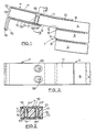
- a leaf spring 1 comprises three superposed spring leaves 2, 3, 4 of composite fibre reinforced synthetic resin material which are constructed in a known manner and are clamped together (not shown).
- the spring leaves are separated by rubbing strips 5, for example of medium carbon steel, secured to the lower surface of each of the leaves 3, 4 and wear plates 6, for example of a polyamide, secured to the upper surfaces of the leaves 2, 3 in rubbing contact with the respective rubbing strips 5.
- the upper leaf 4 has opposed upper and lower surfaces 8, 9 at its end which are enclosed within a bearing member 7.
- the bearing member 7 comprises first and second L-shaped components 7' and 7" respectively.
- the first component 7' has a side part 11 which lies on the upper surface 8 and an end limb 12 which is substantially normal to the side part 11 and extends across and beyond the end face 13 of the leaf 4.
- the second component 7" has a first side part 14 which lies along the lower surface 9 and an end limb 15 which lies along the end limb 12 of the first component 7' and is secured to that end limb 12, as by welding, at 16.
- Nylon packing pieces 10 are interposed between the adjacent respective side parts and upper and lower surfaces of the leaf 4.
- Two laterally spaced holes 17, Figure 3, are drilled through the side parts 11, 14, the packing pieces 10 and the leaf 4 between them. End portions 17' of the holes 17 in the side part 11, 14 are countersunk.
- An internally screw threaded, countersunk, headed sleeve 18 is inserted into each hole 17 from the underside of the bearing member and leaf and is secured with a countersunk head screw 19 inserted from the top of the bearing member and leaf, as best seen in Figure 3.
- the screws 19 are preferably locked with a suitable known thread locking adhesive.
- the bearing member 7 may be bonded, as by an adhesive, onto the end of the leaf 4.
- the bearing member 7, secured to the upper leaf 4 is longitudinally slidably received in a hanger bracket secured to a vehicle.
- the side parts 11, 14 provide abrasion resistant surfaces for the spring within the hanger bracket.
- the end limbs 12, 15 prevent the spring from sliding out of the hanger bracket.
- the weight of the vehicle is applied to the spring through the upper side part 11 of the bearing member which is of a size to spread the load along the end of the upper leaf 4 and to give support to that leaf.
- the upper side 11 extends beyond the ends of the lower leaves 2, 3 of the spring, as shown in Figure 1, so as to assist in distributing the load to all three leaves of the spring, and so that it is at no point solely applied to the leaf 4. This will not, of course, be the case with a single leaf spring.
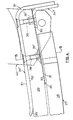
- a leaf spring 27, of which one end only is shown, comprises two superposed spring leaves 28, 29 of composite fibre reinforced synthetic resin material which are clamped together (not shown).
- the spring leaves are separated by a rubbing strip 30 secured at the lower surface of the upper leaf 29 and a wear plate 31 secured to the upper surface of the lower leaf 28 in rubbing contact with the rubbing strip 30.
- the upper leaf 29 has opposed upper and lower surfaces 32, 33 respectively which are enclosed at the end of the leaf within a bearing member 34.
- the bearing member 34 is generally similar to bearing member 7 of the first-described embodiment comprising first and second L-shaped components 34' and 34" respectively. It will be noted, however, that its second component 34" has a shorter side part 35, and the rubbing strip 30 extends to the end of the upper leaf 29 and is secured between the side part 35 and the lower surface 33 of the upper leaf by aligned shouldered bolts 36 and shouldered nuts 36' which secure the bearing member 34 to the end of the leaf 29.
- An upper side part 37 of the first L-shaped component 34' of the bearing member 34 is additionally secured to the upper leaf 29 by aligned bolts 38 and shouldered nuts 38'.
- nuts 38' are recessed into the lower surface of the upper leaf 29 and their outside diameters are increased to spread the load within the leaf.
- a rounded end 39 of the upper side part 37 of the first component 34' will also be noted which is provided to avoid abrasion of the upper surface 32 when the leaf 29 flexes.
- the end of the leaf spring 29 is shown in a hanger bracket 40.
- the sides of the lower spring leaf 28 may be inclined inwardly towards the lower surface of the leaf, and the sides of the upper spring leaf 29 may be inclined inwardly towards the upper surface of that leaf.
- the taper may be of the order of 7°. This is particularly useful where it is desired to replace a conventional steel spring with a composite spring in accordance with the invention without changing the hanger brackets, and it is desired to retain the maximum width for the composite spring to meet performance requirements.
Landscapes
- Engineering & Computer Science (AREA)
- General Engineering & Computer Science (AREA)
- Mechanical Engineering (AREA)
- Springs (AREA)
Claims (9)
Priority Applications (1)
| Application Number | Priority Date | Filing Date | Title |
|---|---|---|---|
| AT83303586T ATE21655T1 (de) | 1982-07-09 | 1983-06-22 | Feder aus faserverbundwerkstoffen. |
Applications Claiming Priority (2)
| Application Number | Priority Date | Filing Date | Title |
|---|---|---|---|
| GB8220052 | 1982-07-09 | ||
| GB8220052 | 1982-07-09 |
Publications (2)
| Publication Number | Publication Date |
|---|---|
| EP0099196A1 EP0099196A1 (de) | 1984-01-25 |
| EP0099196B1 true EP0099196B1 (de) | 1986-08-27 |
Family
ID=10531595
Family Applications (1)
| Application Number | Title | Priority Date | Filing Date |
|---|---|---|---|
| EP83303586A Expired EP0099196B1 (de) | 1982-07-09 | 1983-06-22 | Feder aus Faserverbundwerkstoffen |
Country Status (4)
| Country | Link |
|---|---|
| EP (1) | EP0099196B1 (de) |
| AT (1) | ATE21655T1 (de) |
| DE (1) | DE3365648D1 (de) |
| GB (1) | GB2123521B (de) |
Families Citing this family (4)
| Publication number | Priority date | Publication date | Assignee | Title |
|---|---|---|---|---|
| EP0248603B1 (de) * | 1986-05-31 | 1992-07-29 | Gkn Technology Limited | Blattfederhalterungen |
| US4894108A (en) * | 1988-10-17 | 1990-01-16 | General Motors Corporation | Method of forming a composite leaf spring with fabric wear pad |
| DE10241009A1 (de) * | 2002-09-05 | 2004-03-25 | Bombardier Transportation Gmbh | Vorrichtung zum Einspannen von Faserverbundbauelementen |
| US9765838B2 (en) | 2010-12-06 | 2017-09-19 | Thunder Composite Technologies Ltd. | Composite leaf spring and method of making same |
Family Cites Families (8)
| Publication number | Priority date | Publication date | Assignee | Title |
|---|---|---|---|---|
| DE534959C (de) * | 1931-10-03 | George Alfred Woodhead | Tragblattfeder fuer Kraftfahrzeuge | |
| US1900841A (en) * | 1932-04-11 | 1933-03-07 | Mather Spring Company | Spring construction |
| US2010177A (en) * | 1933-01-03 | 1935-08-06 | Richard L Cramer | Joint for elliptical springs |
| GB566377A (en) * | 1942-10-31 | 1944-12-28 | Jonas Woodhead & Sons Ltd | Improvements in or relating to laminated springs |
| GB686725A (en) * | 1951-01-11 | 1953-01-28 | William David Chaplin | Improvements in or relating to leaf spring connections for wheeled vehicles |
| US3598387A (en) * | 1969-07-01 | 1971-08-10 | Mack Trucks | Spring end assembly |
| US3968958A (en) * | 1972-11-30 | 1976-07-13 | Edgewater Corporation | Composite material springs and manufacture |
| GB2100835B (en) * | 1981-06-15 | 1985-09-25 | Budd Co | Non-metallic leaf spring |
-
1983
- 1983-06-22 GB GB08316920A patent/GB2123521B/en not_active Expired
- 1983-06-22 AT AT83303586T patent/ATE21655T1/de not_active IP Right Cessation
- 1983-06-22 DE DE8383303586T patent/DE3365648D1/de not_active Expired
- 1983-06-22 EP EP83303586A patent/EP0099196B1/de not_active Expired
Also Published As
| Publication number | Publication date |
|---|---|
| DE3365648D1 (en) | 1986-10-02 |
| EP0099196A1 (de) | 1984-01-25 |
| ATE21655T1 (de) | 1986-09-15 |
| GB2123521B (en) | 1986-02-12 |
| GB8316920D0 (en) | 1983-07-27 |
| GB2123521A (en) | 1984-02-01 |
Similar Documents
| Publication | Publication Date | Title |
|---|---|---|
| CA1208245A (en) | Axile clamp for filament reinforced synthetic material leaf springs | |
| EP0889257B1 (de) | Verbesserte Blattfeder, insbesondere für eine Fahrzeugradaufhängung | |
| CA2957852C (en) | Isolated spring clamp group | |
| EP0278596B1 (de) | Klemme für Blattfedern mit Befestigungsvorrichtungen | |
| CA1226594A (en) | Bushings | |
| EP0209552A1 (de) | Gedämpfte feder. | |
| US20200269972A1 (en) | Aircraft assembly | |
| EP0099196B1 (de) | Feder aus Faserverbundwerkstoffen | |
| BR9812529A (pt) | Embuchamento para veìculos pesados | |
| AU723019B2 (en) | Rail pads | |
| EP0343891A1 (de) | Befestigung von Einspannungen an Kunststoff-Blattfedern | |
| US4869472A (en) | Connection devices for spring suspension leaves of a vehicle and method for installing said devices | |
| US20020069539A1 (en) | Blade tensioner | |
| GB2128714A (en) | Fibre-reinforced-plastics springs | |
| US4887802A (en) | Leaf spring assemblies | |
| CA1134335A (en) | Rail fastener | |
| JPS6042042B2 (ja) | 重ね板ばね用クランプ装置 | |
| US20220196101A1 (en) | Noise-reducing element for a leaf spring | |
| JPH0547873Y2 (de) | ||
| CA1190251A (en) | Composite multileaf, multistage leaf spring | |
| EP0246810A1 (de) | Befestigungsteile für Blattfedern aus Mehrkomponentenwerkstoffedern | |
| JPS60136631A (ja) | Frp板ばね装置 | |
| GB2348406A (en) | Torque rod configuration |
Legal Events
| Date | Code | Title | Description |
|---|---|---|---|
| PUAI | Public reference made under article 153(3) epc to a published international application that has entered the european phase |
Free format text: ORIGINAL CODE: 0009012 |
|
| AK | Designated contracting states |
Designated state(s): AT BE CH DE FR IT LI LU NL SE |
|
| 17P | Request for examination filed |
Effective date: 19840702 |
|
| GRAA | (expected) grant |
Free format text: ORIGINAL CODE: 0009210 |
|
| AK | Designated contracting states |
Kind code of ref document: B1 Designated state(s): AT BE CH DE FR IT LI LU NL SE |
|
| REF | Corresponds to: |
Ref document number: 21655 Country of ref document: AT Date of ref document: 19860915 Kind code of ref document: T |
|
| REF | Corresponds to: |
Ref document number: 3365648 Country of ref document: DE Date of ref document: 19861002 |
|
| ET | Fr: translation filed | ||
| ITF | It: translation for a ep patent filed | ||
| PLBI | Opposition filed |
Free format text: ORIGINAL CODE: 0009260 |
|
| PG25 | Lapsed in a contracting state [announced via postgrant information from national office to epo] |
Ref country code: LU Free format text: LAPSE BECAUSE OF NON-PAYMENT OF DUE FEES Effective date: 19870630 |
|
| 26 | Opposition filed |
Opponent name: VERBAND DER DEUTSCHEN FEDERNINDUSTRIE -FAHRZEUGFED Effective date: 19870522 |
|
| NLR1 | Nl: opposition has been filed with the epo |
Opponent name: VERBAND DER DEUTSCHEN FEDERNINDUSTRIE-FAHRZEUGFEDE |
|
| PLBN | Opposition rejected |
Free format text: ORIGINAL CODE: 0009273 |
|
| STAA | Information on the status of an ep patent application or granted ep patent |
Free format text: STATUS: OPPOSITION REJECTED |
|
| 27O | Opposition rejected |
Effective date: 19890528 |
|
| NLR2 | Nl: decision of opposition | ||
| PGFP | Annual fee paid to national office [announced via postgrant information from national office to epo] |
Ref country code: LU Payment date: 19900411 Year of fee payment: 8 |
|
| PGFP | Annual fee paid to national office [announced via postgrant information from national office to epo] |
Ref country code: BE Payment date: 19900423 Year of fee payment: 8 |
|
| PGFP | Annual fee paid to national office [announced via postgrant information from national office to epo] |
Ref country code: FR Payment date: 19900427 Year of fee payment: 8 |
|
| PGFP | Annual fee paid to national office [announced via postgrant information from national office to epo] |
Ref country code: CH Payment date: 19900507 Year of fee payment: 8 |
|
| PGFP | Annual fee paid to national office [announced via postgrant information from national office to epo] |
Ref country code: SE Payment date: 19900612 Year of fee payment: 8 |
|
| PGFP | Annual fee paid to national office [announced via postgrant information from national office to epo] |
Ref country code: AT Payment date: 19900613 Year of fee payment: 8 |
|
| ITTA | It: last paid annual fee | ||
| PGFP | Annual fee paid to national office [announced via postgrant information from national office to epo] |
Ref country code: NL Payment date: 19900630 Year of fee payment: 8 |
|
| PGFP | Annual fee paid to national office [announced via postgrant information from national office to epo] |
Ref country code: DE Payment date: 19900830 Year of fee payment: 8 |
|
| PG25 | Lapsed in a contracting state [announced via postgrant information from national office to epo] |
Ref country code: AT Effective date: 19910622 |
|
| PG25 | Lapsed in a contracting state [announced via postgrant information from national office to epo] |
Ref country code: SE Effective date: 19910623 |
|
| PG25 | Lapsed in a contracting state [announced via postgrant information from national office to epo] |
Ref country code: LI Effective date: 19910630 Ref country code: CH Effective date: 19910630 Ref country code: BE Effective date: 19910630 |
|
| BERE | Be: lapsed |
Owner name: RUBERY OWEN HOLDING LTD Effective date: 19910630 |
|
| PG25 | Lapsed in a contracting state [announced via postgrant information from national office to epo] |
Ref country code: NL Effective date: 19920101 |
|
| NLV4 | Nl: lapsed or anulled due to non-payment of the annual fee | ||
| PG25 | Lapsed in a contracting state [announced via postgrant information from national office to epo] |
Ref country code: FR Effective date: 19920228 |
|
| REG | Reference to a national code |
Ref country code: CH Ref legal event code: PL |
|
| PG25 | Lapsed in a contracting state [announced via postgrant information from national office to epo] |
Ref country code: DE Effective date: 19920401 |
|
| EUG | Se: european patent has lapsed |
Ref document number: 83303586.8 Effective date: 19920109 |