EP0099171B1 - Method of manufacturing a plastic cap - Google Patents
Method of manufacturing a plastic cap Download PDFInfo
- Publication number
- EP0099171B1 EP0099171B1 EP83302459A EP83302459A EP0099171B1 EP 0099171 B1 EP0099171 B1 EP 0099171B1 EP 83302459 A EP83302459 A EP 83302459A EP 83302459 A EP83302459 A EP 83302459A EP 0099171 B1 EP0099171 B1 EP 0099171B1
- Authority
- EP
- European Patent Office
- Prior art keywords
- plunger
- die
- pilfer
- end surface
- cap
- Prior art date
- Legal status (The legal status is an assumption and is not a legal conclusion. Google has not performed a legal analysis and makes no representation as to the accuracy of the status listed.)
- Expired
Links
- 229920003023 plastic Polymers 0.000 title claims description 101
- 239000004033 plastic Substances 0.000 title claims description 101
- 238000004519 manufacturing process Methods 0.000 title claims description 19
- 238000000465 moulding Methods 0.000 claims description 36
- 238000000034 method Methods 0.000 claims description 31
- 230000002093 peripheral effect Effects 0.000 claims description 27
- 239000000463 material Substances 0.000 claims description 21
- 238000002844 melting Methods 0.000 claims description 9
- 230000008018 melting Effects 0.000 claims description 9
- 229920000098 polyolefin Polymers 0.000 claims description 9
- 239000000155 melt Substances 0.000 claims description 5
- 229920000219 Ethylene vinyl alcohol Polymers 0.000 claims description 4
- -1 e.g. Polymers 0.000 description 19
- 239000004743 Polypropylene Substances 0.000 description 11
- 229920001155 polypropylene Polymers 0.000 description 11
- 238000000748 compression moulding Methods 0.000 description 7
- 239000004698 Polyethylene Substances 0.000 description 6
- 229920000573 polyethylene Polymers 0.000 description 6
- 229920005989 resin Polymers 0.000 description 6
- 239000011347 resin Substances 0.000 description 6
- 238000007789 sealing Methods 0.000 description 5
- 230000004888 barrier function Effects 0.000 description 4
- 238000001746 injection moulding Methods 0.000 description 4
- 230000015572 biosynthetic process Effects 0.000 description 3
- 230000006835 compression Effects 0.000 description 3
- 238000007906 compression Methods 0.000 description 3
- 239000000203 mixture Substances 0.000 description 3
- 229920001169 thermoplastic Polymers 0.000 description 3
- 239000004416 thermosoftening plastic Substances 0.000 description 3
- 239000004952 Polyamide Substances 0.000 description 2
- 229920001328 Polyvinylidene chloride Polymers 0.000 description 2
- 238000005520 cutting process Methods 0.000 description 2
- 230000002950 deficient Effects 0.000 description 2
- 238000004455 differential thermal analysis Methods 0.000 description 2
- 229920000092 linear low density polyethylene Polymers 0.000 description 2
- 239000004707 linear low-density polyethylene Substances 0.000 description 2
- 229920001684 low density polyethylene Polymers 0.000 description 2
- 239000004702 low-density polyethylene Substances 0.000 description 2
- FPYJFEHAWHCUMM-UHFFFAOYSA-N maleic anhydride Chemical compound O=C1OC(=O)C=C1 FPYJFEHAWHCUMM-UHFFFAOYSA-N 0.000 description 2
- 229920002647 polyamide Polymers 0.000 description 2
- 239000005033 polyvinylidene chloride Substances 0.000 description 2
- 230000002459 sustained effect Effects 0.000 description 2
- 229920000178 Acrylic resin Polymers 0.000 description 1
- 239000004925 Acrylic resin Substances 0.000 description 1
- 239000004372 Polyvinyl alcohol Substances 0.000 description 1
- 229920001871 amorphous plastic Polymers 0.000 description 1
- 230000003064 anti-oxidating effect Effects 0.000 description 1
- 239000002216 antistatic agent Substances 0.000 description 1
- 239000007767 bonding agent Substances 0.000 description 1
- 235000014171 carbonated beverage Nutrition 0.000 description 1
- 238000004040 coloring Methods 0.000 description 1
- 238000010276 construction Methods 0.000 description 1
- 238000001816 cooling Methods 0.000 description 1
- 229920001577 copolymer Polymers 0.000 description 1
- 229920001887 crystalline plastic Polymers 0.000 description 1
- 239000000945 filler Substances 0.000 description 1
- NBVXSUQYWXRMNV-UHFFFAOYSA-N fluoromethane Chemical compound FC NBVXSUQYWXRMNV-UHFFFAOYSA-N 0.000 description 1
- 239000011521 glass Substances 0.000 description 1
- 238000010438 heat treatment Methods 0.000 description 1
- 229920001903 high density polyethylene Polymers 0.000 description 1
- 239000004700 high-density polyethylene Substances 0.000 description 1
- 238000010030 laminating Methods 0.000 description 1
- 239000007788 liquid Substances 0.000 description 1
- 239000000314 lubricant Substances 0.000 description 1
- 229920001179 medium density polyethylene Polymers 0.000 description 1
- 239000004701 medium-density polyethylene Substances 0.000 description 1
- 239000002184 metal Substances 0.000 description 1
- 238000002156 mixing Methods 0.000 description 1
- 150000002825 nitriles Chemical class 0.000 description 1
- 239000007800 oxidant agent Substances 0.000 description 1
- 229920001225 polyester resin Polymers 0.000 description 1
- 239000004645 polyester resin Substances 0.000 description 1
- 229920005672 polyolefin resin Polymers 0.000 description 1
- 229920002451 polyvinyl alcohol Polymers 0.000 description 1
- 230000000630 rising effect Effects 0.000 description 1
- 229920006395 saturated elastomer Polymers 0.000 description 1
- XLYOFNOQVPJJNP-UHFFFAOYSA-N water Chemical compound O XLYOFNOQVPJJNP-UHFFFAOYSA-N 0.000 description 1
Images


Classifications
-
- B—PERFORMING OPERATIONS; TRANSPORTING
- B29—WORKING OF PLASTICS; WORKING OF SUBSTANCES IN A PLASTIC STATE IN GENERAL
- B29C—SHAPING OR JOINING OF PLASTICS; SHAPING OF MATERIAL IN A PLASTIC STATE, NOT OTHERWISE PROVIDED FOR; AFTER-TREATMENT OF THE SHAPED PRODUCTS, e.g. REPAIRING
- B29C53/00—Shaping by bending, folding, twisting, straightening or flattening; Apparatus therefor
- B29C53/02—Bending or folding
- B29C53/04—Bending or folding of plates or sheets
- B29C53/06—Forming folding lines by pressing or scoring
-
- B—PERFORMING OPERATIONS; TRANSPORTING
- B65—CONVEYING; PACKING; STORING; HANDLING THIN OR FILAMENTARY MATERIAL
- B65D—CONTAINERS FOR STORAGE OR TRANSPORT OF ARTICLES OR MATERIALS, e.g. BAGS, BARRELS, BOTTLES, BOXES, CANS, CARTONS, CRATES, DRUMS, JARS, TANKS, HOPPERS, FORWARDING CONTAINERS; ACCESSORIES, CLOSURES, OR FITTINGS THEREFOR; PACKAGING ELEMENTS; PACKAGES
- B65D41/00—Caps, e.g. crown caps or crown seals, i.e. members having parts arranged for engagement with the external periphery of a neck or wall defining a pouring opening or discharge aperture; Protective cap-like covers for closure members, e.g. decorative covers of metal foil or paper
- B65D41/32—Caps or cap-like covers with lines of weakness, tearing-strips, tags, or like opening or removal devices, e.g. to facilitate formation of pouring openings
- B65D41/34—Threaded or like caps or cap-like covers provided with tamper elements formed in, or attached to, the closure skirt
- B65D41/3423—Threaded or like caps or cap-like covers provided with tamper elements formed in, or attached to, the closure skirt with flexible tabs, or elements rotated from a non-engaging to an engaging position, formed on the tamper element or in the closure skirt
- B65D41/3428—Threaded or like caps or cap-like covers provided with tamper elements formed in, or attached to, the closure skirt with flexible tabs, or elements rotated from a non-engaging to an engaging position, formed on the tamper element or in the closure skirt the tamper element being integrally connected to the closure by means of bridges
-
- B—PERFORMING OPERATIONS; TRANSPORTING
- B29—WORKING OF PLASTICS; WORKING OF SUBSTANCES IN A PLASTIC STATE IN GENERAL
- B29C—SHAPING OR JOINING OF PLASTICS; SHAPING OF MATERIAL IN A PLASTIC STATE, NOT OTHERWISE PROVIDED FOR; AFTER-TREATMENT OF THE SHAPED PRODUCTS, e.g. REPAIRING
- B29C43/00—Compression moulding, i.e. applying external pressure to flow the moulding material; Apparatus therefor
- B29C43/02—Compression moulding, i.e. applying external pressure to flow the moulding material; Apparatus therefor of articles of definite length, i.e. discrete articles
- B29C43/20—Making multilayered or multicoloured articles
- B29C43/203—Making multilayered articles
-
- B—PERFORMING OPERATIONS; TRANSPORTING
- B29—WORKING OF PLASTICS; WORKING OF SUBSTANCES IN A PLASTIC STATE IN GENERAL
- B29C—SHAPING OR JOINING OF PLASTICS; SHAPING OF MATERIAL IN A PLASTIC STATE, NOT OTHERWISE PROVIDED FOR; AFTER-TREATMENT OF THE SHAPED PRODUCTS, e.g. REPAIRING
- B29C43/00—Compression moulding, i.e. applying external pressure to flow the moulding material; Apparatus therefor
- B29C43/32—Component parts, details or accessories; Auxiliary operations
- B29C43/36—Moulds for making articles of definite length, i.e. discrete articles
- B29C43/361—Moulds for making articles of definite length, i.e. discrete articles with pressing members independently movable of the parts for opening or closing the mould, e.g. movable pistons
-
- B—PERFORMING OPERATIONS; TRANSPORTING
- B29—WORKING OF PLASTICS; WORKING OF SUBSTANCES IN A PLASTIC STATE IN GENERAL
- B29C—SHAPING OR JOINING OF PLASTICS; SHAPING OF MATERIAL IN A PLASTIC STATE, NOT OTHERWISE PROVIDED FOR; AFTER-TREATMENT OF THE SHAPED PRODUCTS, e.g. REPAIRING
- B29C43/00—Compression moulding, i.e. applying external pressure to flow the moulding material; Apparatus therefor
- B29C43/32—Component parts, details or accessories; Auxiliary operations
- B29C43/36—Moulds for making articles of definite length, i.e. discrete articles
- B29C43/42—Moulds for making articles of definite length, i.e. discrete articles for undercut articles
-
- B—PERFORMING OPERATIONS; TRANSPORTING
- B29—WORKING OF PLASTICS; WORKING OF SUBSTANCES IN A PLASTIC STATE IN GENERAL
- B29C—SHAPING OR JOINING OF PLASTICS; SHAPING OF MATERIAL IN A PLASTIC STATE, NOT OTHERWISE PROVIDED FOR; AFTER-TREATMENT OF THE SHAPED PRODUCTS, e.g. REPAIRING
- B29C61/00—Shaping by liberation of internal stresses; Making preforms having internal stresses; Apparatus therefor
- B29C61/02—Thermal shrinking
-
- B—PERFORMING OPERATIONS; TRANSPORTING
- B29—WORKING OF PLASTICS; WORKING OF SUBSTANCES IN A PLASTIC STATE IN GENERAL
- B29D—PRODUCING PARTICULAR ARTICLES FROM PLASTICS OR FROM SUBSTANCES IN A PLASTIC STATE
- B29D1/00—Producing articles with screw-threads
-
- B—PERFORMING OPERATIONS; TRANSPORTING
- B65—CONVEYING; PACKING; STORING; HANDLING THIN OR FILAMENTARY MATERIAL
- B65D—CONTAINERS FOR STORAGE OR TRANSPORT OF ARTICLES OR MATERIALS, e.g. BAGS, BARRELS, BOTTLES, BOXES, CANS, CARTONS, CRATES, DRUMS, JARS, TANKS, HOPPERS, FORWARDING CONTAINERS; ACCESSORIES, CLOSURES, OR FITTINGS THEREFOR; PACKAGING ELEMENTS; PACKAGES
- B65D41/00—Caps, e.g. crown caps or crown seals, i.e. members having parts arranged for engagement with the external periphery of a neck or wall defining a pouring opening or discharge aperture; Protective cap-like covers for closure members, e.g. decorative covers of metal foil or paper
- B65D41/32—Caps or cap-like covers with lines of weakness, tearing-strips, tags, or like opening or removal devices, e.g. to facilitate formation of pouring openings
- B65D41/34—Threaded or like caps or cap-like covers provided with tamper elements formed in, or attached to, the closure skirt
-
- B—PERFORMING OPERATIONS; TRANSPORTING
- B29—WORKING OF PLASTICS; WORKING OF SUBSTANCES IN A PLASTIC STATE IN GENERAL
- B29C—SHAPING OR JOINING OF PLASTICS; SHAPING OF MATERIAL IN A PLASTIC STATE, NOT OTHERWISE PROVIDED FOR; AFTER-TREATMENT OF THE SHAPED PRODUCTS, e.g. REPAIRING
- B29C43/00—Compression moulding, i.e. applying external pressure to flow the moulding material; Apparatus therefor
- B29C43/32—Component parts, details or accessories; Auxiliary operations
- B29C43/36—Moulds for making articles of definite length, i.e. discrete articles
- B29C43/361—Moulds for making articles of definite length, i.e. discrete articles with pressing members independently movable of the parts for opening or closing the mould, e.g. movable pistons
- B29C2043/3615—Forming elements, e.g. mandrels or rams or stampers or pistons or plungers or punching devices
- B29C2043/3618—Forming elements, e.g. mandrels or rams or stampers or pistons or plungers or punching devices plurality of counteracting elements
-
- B—PERFORMING OPERATIONS; TRANSPORTING
- B29—WORKING OF PLASTICS; WORKING OF SUBSTANCES IN A PLASTIC STATE IN GENERAL
- B29C—SHAPING OR JOINING OF PLASTICS; SHAPING OF MATERIAL IN A PLASTIC STATE, NOT OTHERWISE PROVIDED FOR; AFTER-TREATMENT OF THE SHAPED PRODUCTS, e.g. REPAIRING
- B29C43/00—Compression moulding, i.e. applying external pressure to flow the moulding material; Apparatus therefor
- B29C43/32—Component parts, details or accessories; Auxiliary operations
- B29C43/36—Moulds for making articles of definite length, i.e. discrete articles
- B29C43/361—Moulds for making articles of definite length, i.e. discrete articles with pressing members independently movable of the parts for opening or closing the mould, e.g. movable pistons
- B29C2043/3615—Forming elements, e.g. mandrels or rams or stampers or pistons or plungers or punching devices
- B29C2043/3631—Forming elements, e.g. mandrels or rams or stampers or pistons or plungers or punching devices moving in a frame for pressing and stretching; material being subjected to compressing stretching
-
- B—PERFORMING OPERATIONS; TRANSPORTING
- B29—WORKING OF PLASTICS; WORKING OF SUBSTANCES IN A PLASTIC STATE IN GENERAL
- B29K—INDEXING SCHEME ASSOCIATED WITH SUBCLASSES B29B, B29C OR B29D, RELATING TO MOULDING MATERIALS OR TO MATERIALS FOR MOULDS, REINFORCEMENTS, FILLERS OR PREFORMED PARTS, e.g. INSERTS
- B29K2023/00—Use of polyalkenes or derivatives thereof as moulding material
-
- B—PERFORMING OPERATIONS; TRANSPORTING
- B29—WORKING OF PLASTICS; WORKING OF SUBSTANCES IN A PLASTIC STATE IN GENERAL
- B29K—INDEXING SCHEME ASSOCIATED WITH SUBCLASSES B29B, B29C OR B29D, RELATING TO MOULDING MATERIALS OR TO MATERIALS FOR MOULDS, REINFORCEMENTS, FILLERS OR PREFORMED PARTS, e.g. INSERTS
- B29K2029/00—Use of polyvinylalcohols, polyvinylethers, polyvinylaldehydes, polyvinylketones or polyvinylketals or derivatives thereof as moulding material
- B29K2029/04—PVOH, i.e. polyvinyl alcohol
-
- B—PERFORMING OPERATIONS; TRANSPORTING
- B29—WORKING OF PLASTICS; WORKING OF SUBSTANCES IN A PLASTIC STATE IN GENERAL
- B29K—INDEXING SCHEME ASSOCIATED WITH SUBCLASSES B29B, B29C OR B29D, RELATING TO MOULDING MATERIALS OR TO MATERIALS FOR MOULDS, REINFORCEMENTS, FILLERS OR PREFORMED PARTS, e.g. INSERTS
- B29K2105/00—Condition, form or state of moulded material or of the material to be shaped
- B29K2105/0085—Copolymers
-
- B—PERFORMING OPERATIONS; TRANSPORTING
- B29—WORKING OF PLASTICS; WORKING OF SUBSTANCES IN A PLASTIC STATE IN GENERAL
- B29L—INDEXING SCHEME ASSOCIATED WITH SUBCLASS B29C, RELATING TO PARTICULAR ARTICLES
- B29L2001/00—Articles provided with screw threads
-
- B—PERFORMING OPERATIONS; TRANSPORTING
- B29—WORKING OF PLASTICS; WORKING OF SUBSTANCES IN A PLASTIC STATE IN GENERAL
- B29L—INDEXING SCHEME ASSOCIATED WITH SUBCLASS B29C, RELATING TO PARTICULAR ARTICLES
- B29L2031/00—Other particular articles
- B29L2031/56—Stoppers or lids for bottles, jars, or the like, e.g. closures
- B29L2031/565—Stoppers or lids for bottles, jars, or the like, e.g. closures for containers
-
- B—PERFORMING OPERATIONS; TRANSPORTING
- B65—CONVEYING; PACKING; STORING; HANDLING THIN OR FILAMENTARY MATERIAL
- B65D—CONTAINERS FOR STORAGE OR TRANSPORT OF ARTICLES OR MATERIALS, e.g. BAGS, BARRELS, BOTTLES, BOXES, CANS, CARTONS, CRATES, DRUMS, JARS, TANKS, HOPPERS, FORWARDING CONTAINERS; ACCESSORIES, CLOSURES, OR FITTINGS THEREFOR; PACKAGING ELEMENTS; PACKAGES
- B65D2401/00—Tamper-indicating means
- B65D2401/15—Tearable part of the closure
- B65D2401/40—Bridges having different cross-sections
-
- Y—GENERAL TAGGING OF NEW TECHNOLOGICAL DEVELOPMENTS; GENERAL TAGGING OF CROSS-SECTIONAL TECHNOLOGIES SPANNING OVER SEVERAL SECTIONS OF THE IPC; TECHNICAL SUBJECTS COVERED BY FORMER USPC CROSS-REFERENCE ART COLLECTIONS [XRACs] AND DIGESTS
- Y10—TECHNICAL SUBJECTS COVERED BY FORMER USPC
- Y10S—TECHNICAL SUBJECTS COVERED BY FORMER USPC CROSS-REFERENCE ART COLLECTIONS [XRACs] AND DIGESTS
- Y10S425/00—Plastic article or earthenware shaping or treating: apparatus
- Y10S425/058—Undercut
Definitions
- the present invention relates to a method of making a plastic cap, and more particularly to a method of manufacturing, by means of compression molding, a plastic cap with a threaded inner surface employed for hermetically sealing the mouth of a container such as a bottle.
- a typical conventional plastic cap i.e., a plastic cap with a threaded inner surface employed for hermetically sealing the mouth of a container such as a bottle made of glass, plastic or metal is manufactured by mainly injection molding.
- the injection molding is a method wherein a molten plastic is injected from a nozzle into a mold to form a molded article with a predetermined shape. Since the method requires the material to have an excellent fluidity, it is general to employ a relatively low-strength plastic having a relatively low molecular weight and a melt flow index of about 10-20 g/10 min.
- caps made of these olefin resins by means of injection molding are susceptible to stress-crack, and are poor in low-temperature impact strength. Further, since this type of caps are also poor in the barrier properties to 0 2 and CO 2 , products contained in the bottles hermetically sealed by the caps are inconveniently apt to change properties thereof.
- a method of manufacturing plastic caps by means of compression molding has recently been proposed in WO 81/00822 or the like.
- the method is such that a molten plastic stock is loaded in a cavity with a shape corresponding to the outer shape of a cap to be formed and then a plunger having in its side surface a groove with a shape corresponding to that of a thread to be formed in the inner surface of the cap is forced into the cavity to compression-mold a cap with a threaded inner surface.
- this method unfavorably requires a comparatively high molding pressure.
- the flow of a resin is apt to clog (owing to setting) at the bridges. Consequently, a molding fault, such as a missing portion, is easily produced at the pilfer-proof band, and moreover, it is inconveniently difficult to form a pilfer-proof band with a complicated shape.
- these shortcomings tend to occur remarkably.
- DE-A-1 479 249 discloses a method of manufacturing an internally-threaded plastics cap, using a first plunger slidable in a bore and forming the internal, threaded, surface of the cap, a second plunger which co-operates in forming the outer surface of the top end of the cap, and a die to form the external surface of the cap.
- the second plunger serves the purpose simply of ejecting the cap from the die when the cap is completed.
- EP-A-26 405 discloses a method of manufacturing a plastics cap in which molten plastics stock is placed on the die bottom and compressed so that the stock flows out from between the plunger and the die bottom.
- an object of the invention to provide a method of manufacturing a plastic cap having a skirt portion whose end portion has an accurate profile, even when a molten plastic stock with a relatively low melt flow index and of a relatively low temperature is used.
- the cap further has a pilfer-proof band (105) having a shape of a short cylinder and being connected to the end surface (103c) of said skirt portion (103) through a plurality of narrow bridges (106);
- the bore of the holding pad (108) has an upper portion through which the first plunger is slidable and a lower portion which is formed with a plurality of linear grooves (110) having a shape corresponding to said bridge (106) on the lower end thereof, and an annular groove (109) connecting to said linear grooves (110) and having a shape corresponding to said pilfer-proof band (105);
- the molten plastic stock (12) is placed onto the upper end surface of said second plunger (6) disposed in proximity of the level of the bottom end surface (108b) of said holding pad (108); said molten plastic stock (12) is compressed between said first and second plungers (5, 6) to form said pilfer-proof band (105) and said bridges (106) between said first plunger (5) and said holding pad (108), while sliding said first plunger
- a cap 1 has a top end 2 and a skirt portion 3 hanging down from a peripheral edge 2a of the top end 2.
- the skirt portion 3 has a thread (see a reference numeral 4 in Fig. 6) formed on its inner surface as well as an axially extending knurl 3b formed on its outer peripheral surface 3a for preventing slippage in hermetical sealing or opening.
- Figs. 2 through 6 show examples of processes and a molding apparatus M for manufacturing the cap 1 of the type mentioned above.
- the molding apparatus M has an upper plunger 5, a lower plunger 6, a die 7 and a holding pad 8.
- the upper plunger 5 has a lower side surface portion 5a i with a shape corresponding to that of the inner peripheral surface of the skirt portion 3 of the cap 1, and the lower side surface portion 5a, has a thread groove 10 with a shape corresponding to that of the thread 4 of the cap 1.
- the bottom end surface 5b of the upper plunger 5 has a shape corresponding to that of the inner surface 2b (see Fig. 6) of the top end 2 of the cap 1.
- the lower plunger 6 has an upper end surface 6a with a shape corresponding to that of the outer surface 2c of the top end 2 of the cap 1 and a side peripheral surface 6b with a shape corresponding to that of the outer peripheral surface 3a of the skirt portion 3, and is adapted to be slidable in a cavity 7a of the die 7 having an inner peripheral surface 7a, with a shape corresponding to also that of the outer peripheral surface 3a of the skirt portion 3. It is to be noted that the die 7 is held in place by means of a holding device, not shown.
- the holding pad 8 is a ring-shaped body having an inner peripheral surface 8a slidable along the side peripheral surface 5a of the upper plunger 5.
- the inside diameter of the inner peripheral surface 8a is equal to the inside diameter of the end surface 3c (see Fig. 6) of the skirt portion 3.
- the height of the inner peripheral surface 8a is set so as to be larger than the height of the thread groove 10, i.e., the height h (see Fig. 3) between the lowest point 10a and the highest point 10b thereof. This is for preventing a plastic stock rising through the thread groove 10 from escaping to the outside in compression molding, explained later.
- the holding pad 8 is adapted to be vertically movable at a predetermined timing by means of a drive mechanism, not shown, through vertical rods 11.
- the upper plunger 5 and the holding pad 8 are raised, and the lower plunger 6 is raised in the die cavity 7a until the upper end surface 6a reaches a position having a predetermined depth from the upper surface 7b of the die 7.
- a molten plastic stock 12 (the weight thereof is substantially equal to the weight of the cap 1 to be formed) is dropped onto the upper end surface 6a so as to be loaded.
- the above-mentioned predetermined depth is usually set so that the volume of a die cavity gap portion 7a 2 defined by the levels of the upper end surface 6a and the die upper surface 7b is substantially equal to the volume of the plastic stock 12.
- the depth may be set such that the level of the side end 6a, of the upper end surface 6a substantially coincides with that of the die upper surface 7b, as described later.
- the die cavity gap portion 7a 2 is shallow in case of the loading of the plastic stock 12, the loading is smoothly effected without causing such a trouble that the plastic stock 12 is caught by the inner peripheral surface 7a, of the die cavity when being loaded.
- the holding pad 8 is lowered in order to bring the lower surface 8b into contact with the die upper surface 7b.
- the upper plunger 5 is lowered to crush the plastic stock 12 into a disc body 12' filling the die cavity gap portion 7a 2 , as shown in Fig. 3.
- the shape of a portion 3c' thereof corresponding to the end surface 3c of the skirt portion of the cap to be formed is accurately defined by a portion 8b 1 of the holding pad bottom surface 8b projecting above the die cavity 7a. Accordingly, it is possible to obtain an accurate shape of the end surface 3c even if the plastic stock 12 is constituted by a plastic with a relatively low melt flow index and has a comparatively low temperature, slightly higher than its melting point.
- thermoplastics e.g., polyolefins such as low-density polyethylene, medium-density polyethylene, high-density' polyethylene, linear low-density polyethylene or isotactic polypropylene, acrylic resins, nitrile resins, saturated polyester resins, or their copolymers or blends.
- a polyethylene or polypropylene with a relatively low melt flow index e.g., about 0.3-10 g/10 min.
- such fillers are generally added to the plastic as a coloring material, lubricant, antistatic agent and anti-oxidizing agent.
- the plastic stock 12 is constituted by a single body of one of these thermoplastics, or a laminate or blend formed by laminating or blending, with one of these thermoplastics employed as a main body, a resin with barrier properties to 0 2 and C0 2 , e.g., ethylene-vinyl alcohol copolymer, polyamide, polyvinylidene chloride or polyvinyl alcohol and the like.
- A is a high-density or linear low-density polyethylene or polypropylene
- B is an acid-modified polyolefin of the selected A (functioning as a bonding agent)
- C is an ethylene-vinyl alcohol copolymer or polyamide or polyvinylidene chloride.
- the plastic stock 12 constituted by a plastic single body or blend is generally formed by cutting a melt extruded body.
- a stock which is previously formed by cutting a sheet-like laminate into the shape of the disc body 12' shown in Fig. 3 may be placed in a pan having a recess (preferably having an inner surface coated with a fluorocarbon resin) with a shape corresponding to that of the stock and heated to a predetermined temperature in an oven or the like. Then, the heated plastic stock is loaded in the die cavity gap portion 7a 2 , and molding is started from the state shown in Fig. 3.
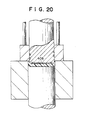
- a cap having a liner layer of the above relatively soft plastic as a sealing member may be made in accordance with this invention, as indicated in Figs. 19, 20 and 21.
- the temperature of the material of the plastic stock 12 during molding is maintained at a temperature above the melting point of the plastic concerned (in case of a crystalline plastic) or the liquid-state flow starting point thereof (in case of an amorphous plastic). This is for the purpose of ensuring the adhesion between the thread 4 to be formed and the skirt portion 3.
- the melting point is defined as the temperature corresponding to the peak of a melt endothermic curve measured by means of the differential thermal analysis under the atmospheric pressure.
- the liquid-state flow starting point is defined as the temperature at which a resin starts liquid-state flow discharge from a nozzle having a diameter of 1 mm and a length of 10 mm when heated under a plunger pressure 160 kg/cm 2 and at a uniform rate, by employing a Kouka type flow tester indicated in JIS (Japanese Industrial Standards) K6719.
- the polyolefin forming the cap 1 should be molecularly oriented, in order to prevent stress crack (apt to be caused by the stress generated in the cap by the internal pressure in case of hermetically sealing a container filled with, particularly, a positive internal-pressure type liquid such as carbonated beverages) from generating in the formed cap 1.
- the temperature of the plastic stock 12 (the temperature thereof when it is supplied onto the lower plunger 6, or the temperature of the plastic stock 12 after it is thus applied and heated by means of a heater) and the temperatures of each of the lower side surface portion 5a 1 of the upper plunger, the upper end surface 6a of the lower plunger, the inner peripheral surface 8a of the holding pad 8 and the die cavity inner peripheral surface 7a 1 and the like, are set to that the material of the plastic stock 12 is maintained within the above-mentioned temperature range during molding.
- the surfaces of the upper plunger 5, the lower plunger 6 and the die 7 contacting the material of the plastic stock 12 during molding are kept at a predetermined temperature for ensuring the stability of forming.
- a cooler (not shown), and if necessary, a heater (not shown) is incorporated in each of the upper plunger 5, the lower plunger 6 and the die 7.
- a heater (not shown) is incorporated in each of the upper plunger 5, the lower plunger 6 and the die 7.
- the temperature be as low (e.g., 20°C) as possible, using the cooler as long as the material during molding is maintained within the above-mentioned temperature range.
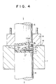
- the lowering rates of the plungers are controlled by means of a drive control mechanism (e.g., hydraulic mechanism), not shown, so that the lowering rate of the upper plunger 5 is larger than that of the lower plunger 6 and moreover the upper end surface 3'a of the sidewall portion 3' of the molded piece 1' is substantially brought into contact with a portion of the bottom surface 8b of the holding pad 8 corresponding thereto (see Fig. 4).
- a drive control mechanism e.g., hydraulic mechanism
- the sidewall portion 3' is formed by the material flowing, by means of the above-mentioned compression from the bottom wall portion 2' of the molded piece 1' to between the lower side surface portion 5a, of the upper plunger 5 and the die cavity inner peripheral surface 7a, in the direction of an arrow F.
- the thread 4 is formed, while moving downwardly, on the portion of the molded piece 1' corresponding to the thread groove 10 of the upper plunger 5. It is to be noted that although the material also flows in the thread groove 10 positioned along the holding pad 8 up to a portion near the highest point lOa 2 during molding, since the height of the inner peripheral surface 8a of the holding pad 8 is set so as to be larger than the above-mentioned height h, there is no possibility that the material may escape to the outside, resulting in defectives having short of weight.
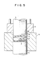
- the cap 1 When the upper plunger 5 and the lower plunger 6 reach the bottom dead point, the cap 1 is formed having the top end 2 and the skirt portion 3 together with the thread 4 formed on the inner surface thereof, as shown in Fig. 5.
- the end surface 3c of the skirt portion 3 is defined by the lower surface 8b of the holding pad 8 as described above.
- the cap 1 After the cap 1 has been cooled and solidified, as shown in Fig. 6, the upper plunger 5, the lower plunger 6 and the holding pad 8 are raised, and the cap 1 is removed from the die 7. Then, while a pressurized air is being sent from a pressurized- air source, not shown, to an air inlet bore 14 (having at its lower end a plug 16 normally brought into close contact with the truncated core-shaped lower end portion of the air inlet bore 14 by means of a spring 15) formed inside the upper plunge-r5, only the upper plunger 5 is raised under the state where the end surface 3c of the skirt portion 3 is engaged by the bottom surface 8b of the fixed holding pad 8. Consequently, the skirt portion 3 is elastically expanded, and the cap 1 is removed from the upper plunger 5. Alternatively, the cap 1 may be removed from the upper plunger 5 by unscrewing the upper plunger 5 or the cap 1.
- the plastic stock 12 is introduced into the die cavity 7a by fixing the die 7 and compressing the plastic stock 12 between the upper plunger 5 and the lower plunger 6.
- the plastic stock 12 may be introduced into the die cavity 7a by fixing the lower plunger 6, lowering the upper plunger 5 and raising the die 7 while compressing the plastic stock 12 between the upper plunger 5 and the lower plunger 6.
- the plastic stock 12 may be introduced into the die cavity 7a by fixing the upper plunger 5 and raising the lower plunger 6 and the die 7 while compressing the plastic stock 12 between the upper plunger 5 and the lower plunger 6.
- the plastic stock 12 may be introduced into the die cavity 7a by properly vertically moving the die 7, the upper plunger 5 and the lower plunger 6.
- Fig. 7 shows a heat-shrinkable pilfer-proof plastic cap 101.
- the end surface 103c of a skirt portion 103 is connected to a pilfer-proof band 105 in the shape of a short cylinder through a plurality of narrow bridges 106.
- the pilfer-proof band 105 surrounding the jaw of an annular land below the thread of the container mouth is shrunk on heating, thereby allowing the pilfer-proof band 105 to engage with the jaw.
- Figs. 8 through 10 show essential portions of the processes and a molding apparatus N for manufacturing the pilfer-proof cap 101.
- Like reference numerals designate like portions or members in Fig. 3 and these Figures. The same is the case with infra Fig. 11.
- the molding apparatus N is similar to the molding apparatus M shown in Fig. 3 except that a holding pad 108 has in the lower part of its inner surface 108a an annular groove 109 with a shape corresponding to that of the pilfer-proof band 105, together with a plurality of linear grooves 110 having a shape corresponding to that of the bridges 106 and extending from the lower end of the annular groove 109 to the lower surface 108b of the holding pad 108.
- the method of manufacturing the cap 101 is also similar to that of the cap 1.
- the upper end surface 6a of the lower plunger 6 is initially positioned as high as possible, preferably such that the side end 6a, reaches the level of the upper surface 7b of the die 7, as shown in Fig. 8.
- the plastic stock 12 After the plastic stock 12 is mounted on the lower plunger 6, the plastic stock 12 is compressed between the lowering upper plunger 5 and the lower plunger sustained in a stationary state, whereby the material of the plastic stock 12 fills substantially the annular groove 109 and the linear grooves 110.
- the plastic stock 12 is introduced into the die cavity 7a, being compressed between the lowering upper plunger 5 and the lowering lower plunger 6. Consequently, in the early stage of the introduction, the material fills completely the linear grooves 110 and the annular groove 109 and the thread groove 10, as shown in Fig. 9.
- Fig. 10 shows the state where molding is completed and the cap 101 has been formed having a sound healthy pilfer-proof band 109 and sound bridges 110.
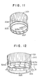
- a pilfer-proof cap 201 shown in Fig. 11 has a pilfer-proof band 205 and bridges 206 similarly to the cap 101, but differs therefrom in that a plurality of leaf-like projections 207 are formed on the inner surface of the pilfer-proof band 205.
- Each leaf-like projection 207 is usually triangular and has its upper end surface 207a disposed on a plane perpendicular to the axis thereof. The upper end surface 207a may be inclined to the plane.
- each leaf-like projection 207 engages with each other.
- a cap 321, shown in Fig. 12 has a ring-shaped pilfer-proof band 325 which is connected to a skirt portion 323 through a plurality of long and slender bridges 324 (e.g., 4 mm (length)xl mmxO.6 mm) downwardly extending from the lower end of the skirt portion 323 and each having thin weak portions 324a and 324b.
- the inside diameter of the pilfer-proof band 325 is substantially equal to that of the portion of the inner surface of the skirt portion 323 where no thread is formed.
- the height of the band 325 is substantially equal to or slightly larger than the height (e.g., 4 mm) of the bridges 324.
- the band 325 is formed with a plurality of leaf-like projections 326 on the outer surface thereof.
- the cap 321 can be formed into a pilfer-proof cap 321a a having the leaf-like projections 326 disposed on the inner surface of the pilfer-proof band 325 by inverting the pilfer-proof band 325 in the direction of an arrow A, i.e., toward inside the bridges 324.
- the cap 321 can be formed into a pilfer-proof cap 321b having the leaf-like projections 326 disposed on the inner surface of the pilfer-proof band 325 by inverting the pilfer-proof band 325 in the direction of an arrow B, i.e., toward outside of the bridges 324.
- the leaf-like projections 326 engage with the outer surface of the annular land below the thread of the container mouth or the lower surface of the jaw (not shown) thereof. Therefore, there is no possibility that the pilfer-proof band may be raised together with the skirt portion 323 in opening, but the bridges 324 are cut at the thin weak portion 324b, thereby allowing the pilfer-proof properties to be ensured.
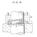
- Figs. 15 and 16 in combination show a method of forming the cap 321.
- the holding pad 328 has grooves 334 with a shape corresponding to that of the bridges 324, small projections 334a, 334b with shapes corresponding to those of the thin weak portions 324a, 324b, respectively, and a groove 335 with a shape corresponding to that of the pilfer-proof band 325. Moreover, a plurality of recesses 336 with a shape corresponding to that of the leaf-like projections 326 are formed along the outer peripheral surface of the groove 335.
- the cap 321 having the bridges 324, the thin weak portions 324a, 324b, the pilfer-proof band 325 and the leaf-like projections 326 can be formed in the same manner as that for manufacturing the cap 101, as shown in Fig. 16.
- the plastic stock 12 is introduced into the die cavity 7a, being compressed between the upper plunger 5 and the lower plunger 6.
- the removal of the formed cap 321 can be easily effected without breaking the bridges 324, since, when the upper plunger 5 is raised, an inward relief for the pilfer-proof band 325 is provided, whereby the holding pad 328 can be raised without any damage to the leaf-like projections 326 and the bridges 324.
- Figs. 17 and 18 show an embodiment for making a cap 1" having an improved gas barrier property, using a plastic stock 12" formed from a laminate consisting of a polypropylene layer (A) 12"a i , a maleic anhydride modified polypropylene layer (B: a bonding layer) 12"b 1 , an ethylene vinyl-alcohol copolymer layer (C) 12"c, a maleic anhydride modified polypropylene layer (B) 12"b 2 and a polypropylene layer (A) 12"a 2' the thickness ratio of the layers A:B:C being 93:3:4.
- Figs. 19, 20 and 21 show an embodiment for making a cap 401 having a liner layer 408 formed integrally in the similar manner with the case of making the cap 1, except in that the plastic stock 12" is formed from a laminate consisting essentially of a low density polyethylene layer 12"'a and a polypropylene layer 12"'b, the polyethylene layer 12"'a facing the upper plunger 405, and the upper plunger 405 is formed with a recess 405a having a shape corresponding to that of the liner layer 408 on the bottom end surface thereof.
- the polypropylene layer 12"'b forms the cap 401, and the polyethylene layer 12"'a forms the liner layer 408. It is preferable that the diameter of the plastic stock 12'" is slightly smaller than the inner diameter of the recess 405a, and the volume of the polyethylene layer 12"'a is not larger than that of the recess 405a.
- isotactic polypropylene having a density (at 20°C) of 0.90 g/cm 3 , a melting point (determined by the differential thermal analysis method) of 162°C, and a melt flow index (measured at 23°C and under the load of 2160 g) of 0.31 g/10 min.
- a portable extruder 500 as shown in Fig. 22 was used for supplying the plastic stock 12.
- the extruder 500 is incorporated with a full-flighted screw having the diameter of 40 mm and the effective length of 880 mm, and is provided with a rotary cutter 502 at the nozzle portion thereof.
- the molding apparatus N of the type shown in Fig. 8 was employed, wherein the diameter of the upper plunger 5 was 28 mm, and the center line of the thread groove 10 starts at the position of 3.5 mm above the bottom end surface of the upper plunger 5, forming one and half turn with a pitch of 8 grooves per inch.
- the height of the holding pad 108 was 10 mm, and the height and the depth of the annular groove 109 were 4 mm and 0.6 mm, respectively.
- the height, the depth and the width of the linear groove 110 were 1 mm, 0.6 mm and 0.5 mm, respectively.
- the inner surface of the die 7 was formed with knurls extending axially, and has the diameter of 30 mm measured along the apexes of the knurls.
- the upper plunger 5, the lower plunger 6, the die 7 and the holding pad 108 are constructed to be driven or fixed independently or in a cooperating mode by means of a hydraulic circuit.
- a system comprising the stock supplying apparatus R and the molding apparatus N is shown in Fig. 22.
- the molten resin 12A of 170°C extruded from the nozzle portion of the portable extruder 500 was cut by a predetermined amount (2.58 g) by means of a rotary cutter 502 driven by a constant speed motor 501, and was allowed to drop onto the upper end surface 6a of the lower plunger 6, which is disposed as shown in Fig. 8 with respect to the die 7.
- the stock supplying apparatus R was retracted in the direction of arrow A to the position where the molding was not hindered.
- the surface temperatures of the die 7, the holding pad 108, the upper plunger 5 and the lower plunger 6 were set to 30°C.
- the plastic stock 12 was placed onto the upper surface of the lower plunger 6 and pressed to fill the annular groove 109 and the linear grooves 110, between the lowering the upper plunger 5 and the lower plunger 6 at a standstill with the fixed die 7. Then the plastic stock 12 was introduced into the cavity 7a of the fixed die 7 with the lowering speed 50 mm/sec of the upper plunger 5 while compressed with a pressure of 130 Kg/cm 2 . After the lower plunger 6 was lowered by 16 mm, the apparatus N was stopped, and caps 101A thus formed were removed from the upper plunger 5.
- caps 101B were made.
- Caps 101C 1 , 101C 2 and 101C 3 were made by the conventional compression molding as described hereinbelow.
- the lower plunger 6, the die 7 and the holding pad 108 (whose surface temperatures were Kept at 30°C) were fixed such that the upper end surface 6a of the lower plunger 6 was disposed at the level lower by 16 mm than the bottom surface 108b of the holding pad 108, and the die 7 was in close contact with the holding pad 108.
- the upper plunger 5 was lowered with a speed of 50 mm/sec and final compression pressures of 130 Kg/cm 2 (for the cap 101C 1 ), 200 Kg/cm 2 (for the cap 101C 2 ) and 250 Kg/cm 2 (for the cap 101C 3 ).
- the cut pilfer-proof bands were immersed in an oil bath of 140°C for 10 seconds, and then the shrinkage ratio and the shapes after the shrinkage were evaluated.
Landscapes
- Engineering & Computer Science (AREA)
- Mechanical Engineering (AREA)
- Physics & Mathematics (AREA)
- Thermal Sciences (AREA)
- Casting Or Compression Moulding Of Plastics Or The Like (AREA)
- Closures For Containers (AREA)
- Moulding By Coating Moulds (AREA)
- Shaping By String And By Release Of Stress In Plastics And The Like (AREA)
Description
- The present invention relates to a method of making a plastic cap, and more particularly to a method of manufacturing, by means of compression molding, a plastic cap with a threaded inner surface employed for hermetically sealing the mouth of a container such as a bottle.
- A typical conventional plastic cap, i.e., a plastic cap with a threaded inner surface employed for hermetically sealing the mouth of a container such as a bottle made of glass, plastic or metal is manufactured by mainly injection molding. The injection molding is a method wherein a molten plastic is injected from a nozzle into a mold to form a molded article with a predetermined shape. Since the method requires the material to have an excellent fluidity, it is general to employ a relatively low-strength plastic having a relatively low molecular weight and a melt flow index of about 10-20 g/10 min.
- Accordingly, in order to ensure a required cap strength, it is necessary to make the top end and skirt portion of the cap have a relatively large wall thickness, which unfavorably results in a higher material cost.
- Moreover, as a plastic stock, it is preferable from the viewpoint of cost to select a material from polyolefins, e.g., polyethylene or polypropylene. However, caps made of these olefin resins by means of injection molding are susceptible to stress-crack, and are poor in low-temperature impact strength. Further, since this type of caps are also poor in the barrier properties to 02 and CO2, products contained in the bottles hermetically sealed by the caps are inconveniently apt to change properties thereof.
- On the other hand, a method of manufacturing plastic caps by means of compression molding has recently been proposed in WO 81/00822 or the like. The method is such that a molten plastic stock is loaded in a cavity with a shape corresponding to the outer shape of a cap to be formed and then a plunger having in its side surface a groove with a shape corresponding to that of a thread to be formed in the inner surface of the cap is forced into the cavity to compression-mold a cap with a threaded inner surface.
- In this method, however, since the end of the skirt portion of the cap is formed in the last stage, in order to ensure an accurate profile of the end portion, it is necessary to employ a plastic excellent in fluidity, i.e., relatively high in melt flow index (although not so high as is in the injection molding).
- In addition, this method unfavorably requires a comparatively high molding pressure. Particularly, in case of manufacturing a cap having a pilfer-proof band connecting the skirt portion through narrow bridges, the flow of a resin is apt to clog (owing to setting) at the bridges. Consequently, a molding fault, such as a missing portion, is easily produced at the pilfer-proof band, and moreover, it is inconveniently difficult to form a pilfer-proof band with a complicated shape. Particularly, in case where the skirt portion is high, these shortcomings tend to occur remarkably.
- In addition, since the cavity is deep, it is often that when the molten plastic stock is loaded in the cavity by dropping, the plastic stock is caught by the sidewall of the cavity, resulting in an unsatisfactory compression molding. Moreover, since the amount of air to be removed in the cavity is large, it is conveniently necessary to employ a special means for removal of the air.
- DE-A-1 479 249 discloses a method of manufacturing an internally-threaded plastics cap, using a first plunger slidable in a bore and forming the internal, threaded, surface of the cap, a second plunger which co-operates in forming the outer surface of the top end of the cap, and a die to form the external surface of the cap. However, the second plunger serves the purpose simply of ejecting the cap from the die when the cap is completed.
- EP-A-26 405 discloses a method of manufacturing a plastics cap in which molten plastics stock is placed on the die bottom and compressed so that the stock flows out from between the plunger and the die bottom.
- It is, therefore, an object of the invention to provide a method of manufacturing a plastic cap having a skirt portion whose end portion has an accurate profile, even when a molten plastic stock with a relatively low melt flow index and of a relatively low temperature is used.
- It is another object of the invention to provide a method of manufacturing a pilfer-proof plastic cap having a satisfactory pilfer-proof band with no missing portion and sound bridges, even when a molten plastic stock with relatively low melt flow index and of a relatively low temperature is used, and the pilfer-proof band has a complicated configuration.
- According to the invention, there is provided a method of manufacturing a plastic cap (1) having ' a top end (2) and a skirt portion (3) hanging down from the peripheral edge of said top end (2), said skirt portion (3) being provided with a thread (4) formed on the inner surface thereof, by using a first plunger (5) whose lower side surface portion (5a,) has a shape corresponding to the inner surface of said skirt portion (3) and is formed with a thread groove (10) with a shape corresponding to that of said thread (4) and whose bottom end surface (5b) has a shape corresponding to that of the inner surface of said top end (2), a second plunger (6) whose upper end surface (6a) has a shape corresponding to that of the outer surface of said top end (2), a holding pad (8) with a bore through which said first plunger (5) is slidable, the bore having a height larger than that of said thread groove (10) as well as an inside diameter substantially equal to the outside diameter of said first plunger (5), and a die (7) provided with a die cavity (7a) having an inner peripheral surface (7a,) with a shape corresponding to that of the outer peripheral surface of said skirt portion (3); characterised by
- (a) placing a molten plastic stock (12) onto the upper end surface (6a) of said second plunger (6), said upper end surface (6a) being positioned at a level such that the volume of a die cavity gap portion above said upper end surface and below the level of the upper surface (7b) of said die (7) is substantially equal to or less than the volume of the molten plastics stock (12);
- (b) bringing the bottom surface (8b) of the holding pad (8) into contact with the upper surface of the die; and
- (c) compressing said molten plastic stock (12) between said first and second plungers (5, 6), while sliding said first plunger along the inner peripheral surface of the bore of the holding pad (8) and into the die cavity and sliding the second plunger along said cavity, thereby causing the molten plastics stock to flow out from between the first and second plungers, whereby said skirt portion (3) is formed by the material of said stock flowing out from between said first and second plungers (5, 6) into between said lower side surface portion (5a,) of said first plunger (5) and said inner peripheral surface (7ai) of said die cavity (7a), and at an early stage of the forming, the end surface of the skirt portion is defined by a projecting portion of the bottom surface of the holding pad above the cavity.
- Preferably the cap further has a pilfer-proof band (105) having a shape of a short cylinder and being connected to the end surface (103c) of said skirt portion (103) through a plurality of narrow bridges (106); the bore of the holding pad (108) has an upper portion through which the first plunger is slidable and a lower portion which is formed with a plurality of linear grooves (110) having a shape corresponding to said bridge (106) on the lower end thereof, and an annular groove (109) connecting to said linear grooves (110) and having a shape corresponding to said pilfer-proof band (105); the molten plastic stock (12) is placed onto the upper end surface of said second plunger (6) disposed in proximity of the level of the bottom end surface (108b) of said holding pad (108); said molten plastic stock (12) is compressed between said first and second plungers (5, 6) to form said pilfer-proof band (105) and said bridges (106) between said first plunger (5) and said holding pad (108), while sliding said first plunger (5) along the upper portion of the bore of the holding pad (8) without sliding the second plunger (6); and then the skirt portion (103) is formed and at an early stage of the forming, the pilfer-proof band (105) and the narrow bridge (100) are defined by the annular groove and the linear grooves, respectively.
- Reference is made to the drawings, in which:
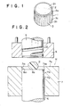
- Fig. 1 is a perspective view of a first example of caps manufactured by the method of the invention;
- Figs. 2 through 6 are sectional side elevations illustrating examples of processes of manufacturing the cap shown in Fig. 1, respectively, Fig. 2 illustrating the state where a plastic stock is loaded, Fig. 3 illustrating a state just before molding, Fig. 4 illustrating a state during the molding, Fig. 5 illustrating a state after completion of the molding, Fig. 6 illustrating a state just before the cap is removed from an upper plunger;
- Fig. 7 is a perspective view of a pilfer-proof cap as a second example of the caps manufactured by the method of the invention;
- Figs. 8 through 10 are sectional side elevations illustrating examples of processes of manufacturing the cap shown in Fig. 7, Fig. 8 illustrating the state where a plastic stock is loaded, Fig. 9 illustrating the state of molding in its early stage,
- Fig. 10 illustrating a state after completion of the molding;
- Fig. 11 is a perspective view of a conventional pilfer-proof cap having leaf-like projections;
- Fig. 12 is a perspective view of a third example of the cap manufactured by the method of the invention;
- Fig. 13 is a perspective view of a pilfer-proof cap having the pilfer-proof band of the cap shown in Fig. 12 inverted toward inside the bridges thereof;
- Fig. 14 is a perspective view of a pilfer-proof cap having the pilfer-proof band of the cap shown in Fig. 12 inverted toward outside the bridges thereof;
- Figs. 15 and 16 are sectional side elevations illustrating a state at the early stage of forming the cap shown in Fig. 12, and a state just after the completion of formation of the cap shown in Fig. 12, respectively;
- Figs. 17 and 18 are sectional side elevations illustrating a state just before a cap is formed from a plastic stock of a laminate, and a state just after the completion of formation of the cap, respectively;
- Figs. 19, 20 and 21 are sectional side elevations illustrating a state just before a cap having a liner layer is integrally formed, a state at the early stage of forming the cap, and a state just after the completion of formation of the cap, respectively; and
- Fig. 22 is a perspective view illustrating an example of a system comprising a plastic stock supplying apparatus and a molding apparatus.
- Referring to Fig. 1 showing an example of plastic caps (referred to as simply "cap" hereinafter) manufactured by the method of the invention, a cap 1 has a
top end 2 and askirt portion 3 hanging down from a peripheral edge 2a of thetop end 2. Theskirt portion 3 has a thread (see areference numeral 4 in Fig. 6) formed on its inner surface as well as an axially extendingknurl 3b formed on its outer peripheral surface 3a for preventing slippage in hermetical sealing or opening. - Figs. 2 through 6 show examples of processes and a molding apparatus M for manufacturing the cap 1 of the type mentioned above.
- The molding apparatus M has an
upper plunger 5, alower plunger 6, a die 7 and aholding pad 8. Theupper plunger 5 has a lower side surface portion 5ai with a shape corresponding to that of the inner peripheral surface of theskirt portion 3 of the cap 1, and the lower side surface portion 5a, has athread groove 10 with a shape corresponding to that of thethread 4 of the cap 1. Moreover, thebottom end surface 5b of theupper plunger 5 has a shape corresponding to that of theinner surface 2b (see Fig. 6) of thetop end 2 of the cap 1. - The
lower plunger 6 has anupper end surface 6a with a shape corresponding to that of theouter surface 2c of thetop end 2 of the cap 1 and a sideperipheral surface 6b with a shape corresponding to that of the outer peripheral surface 3a of theskirt portion 3, and is adapted to be slidable in acavity 7a of thedie 7 having an innerperipheral surface 7a, with a shape corresponding to also that of the outer peripheral surface 3a of theskirt portion 3. It is to be noted that thedie 7 is held in place by means of a holding device, not shown. - The
holding pad 8 is a ring-shaped body having an inner peripheral surface 8a slidable along the side peripheral surface 5a of theupper plunger 5. The inside diameter of the inner peripheral surface 8a is equal to the inside diameter of theend surface 3c (see Fig. 6) of theskirt portion 3. On the other hand, the height of the inner peripheral surface 8a is set so as to be larger than the height of thethread groove 10, i.e., the height h (see Fig. 3) between the lowest point 10a and the highest point 10b thereof. This is for preventing a plastic stock rising through thethread groove 10 from escaping to the outside in compression molding, explained later. It is to be noted that theholding pad 8 is adapted to be vertically movable at a predetermined timing by means of a drive mechanism, not shown, throughvertical rods 11. - In the above molding apparatus M, as shown in Fig. 2, first, the
upper plunger 5 and theholding pad 8 are raised, and thelower plunger 6 is raised in thedie cavity 7a until theupper end surface 6a reaches a position having a predetermined depth from theupper surface 7b of thedie 7. Under this state, a molten plastic stock 12 (the weight thereof is substantially equal to the weight of the cap 1 to be formed) is dropped onto theupper end surface 6a so as to be loaded. The above-mentioned predetermined depth is usually set so that the volume of a diecavity gap portion 7a2 defined by the levels of theupper end surface 6a and the dieupper surface 7b is substantially equal to the volume of theplastic stock 12. However, the depth may be set such that the level of theside end 6a, of theupper end surface 6a substantially coincides with that of the dieupper surface 7b, as described later. - Accordingly, since the die
cavity gap portion 7a2 is shallow in case of the loading of theplastic stock 12, the loading is smoothly effected without causing such a trouble that theplastic stock 12 is caught by the innerperipheral surface 7a, of the die cavity when being loaded. - Then, the
holding pad 8 is lowered in order to bring thelower surface 8b into contact with the dieupper surface 7b. With thelower plunger 6 sustained, theupper plunger 5 is lowered to crush theplastic stock 12 into a disc body 12' filling the diecavity gap portion 7a2, as shown in Fig. 3. In this case, since theplastic stock 12 is still practically hot, the shape of aportion 3c' thereof corresponding to theend surface 3c of the skirt portion of the cap to be formed is accurately defined by aportion 8b1 of the holdingpad bottom surface 8b projecting above thedie cavity 7a. Accordingly, it is possible to obtain an accurate shape of theend surface 3c even if theplastic stock 12 is constituted by a plastic with a relatively low melt flow index and has a comparatively low temperature, slightly higher than its melting point. - As the plastic constituting the
plastic stock 12, it is possible to employ any desired one of thermoplastics, e.g., polyolefins such as low-density polyethylene, medium-density polyethylene, high-density' polyethylene, linear low-density polyethylene or isotactic polypropylene, acrylic resins, nitrile resins, saturated polyester resins, or their copolymers or blends. However, from the viewpoint of cost, a polyethylene or polypropylene with a relatively low melt flow index (e.g., about 0.3-10 g/10 min.) is particularly preferable. In this case, such fillers are generally added to the plastic as a coloring material, lubricant, antistatic agent and anti-oxidizing agent. - The
plastic stock 12 is constituted by a single body of one of these thermoplastics, or a laminate or blend formed by laminating or blending, with one of these thermoplastics employed as a main body, a resin with barrier properties to 02 and C02, e.g., ethylene-vinyl alcohol copolymer, polyamide, polyvinylidene chloride or polyvinyl alcohol and the like. - In case of a laminate, it is preferable to employ a five-layer laminate comprising A-B-C-B-A, having gas barrier properties to water vapor, 02 and C02 as well as a proper strength, in which: A is a high-density or linear low-density polyethylene or polypropylene, B is an acid-modified polyolefin of the selected A (functioning as a bonding agent) and C is an ethylene-vinyl alcohol copolymer or polyamide or polyvinylidene chloride.
- The
plastic stock 12 constituted by a plastic single body or blend is generally formed by cutting a melt extruded body. In case of a plastic stock constituted by a laminate, a stock which is previously formed by cutting a sheet-like laminate into the shape of the disc body 12' shown in Fig. 3 may be placed in a pan having a recess (preferably having an inner surface coated with a fluorocarbon resin) with a shape corresponding to that of the stock and heated to a predetermined temperature in an oven or the like. Then, the heated plastic stock is loaded in the diecavity gap portion 7a2, and molding is started from the state shown in Fig. 3. - By using a disc body 12' formed from a laminate consisting essentially of an upper layer of a relatively soft plastic facing the
upper plunger 5 and a lower layer of a relatively hard plastic facing thelower plunger 6, a cap having a liner layer of the above relatively soft plastic as a sealing member may be made in accordance with this invention, as indicated in Figs. 19, 20 and 21. - The temperature of the material of the
plastic stock 12 during molding is maintained at a temperature above the melting point of the plastic concerned (in case of a crystalline plastic) or the liquid-state flow starting point thereof (in case of an amorphous plastic). This is for the purpose of ensuring the adhesion between thethread 4 to be formed and theskirt portion 3. - Here, the melting point is defined as the temperature corresponding to the peak of a melt endothermic curve measured by means of the differential thermal analysis under the atmospheric pressure. On the other hand, the liquid-state flow starting point is defined as the temperature at which a resin starts liquid-state flow discharge from a nozzle having a diameter of 1 mm and a length of 10 mm when heated under a plunger pressure 160 kg/cm2 and at a uniform rate, by employing a Kouka type flow tester indicated in JIS (Japanese Industrial Standards) K6719.
- In the case where the
plastic stock 12 mainly consists of polyolefin, it is desirable that the polyolefin forming the cap 1 should be molecularly oriented, in order to prevent stress crack (apt to be caused by the stress generated in the cap by the internal pressure in case of hermetically sealing a container filled with, particularly, a positive internal-pressure type liquid such as carbonated beverages) from generating in the formed cap 1. - It is possible to obtain a molecularly oriented cap 1 in the case where the temperature of the material during molding is not higher than a temperature which is the melting point of the plastic concerned plus 40°C. Accordingly, in this case, molding is performed at a temperature not less than the melting point of the plastic concerned as well as not more than the melting point plus 40°C. In consequence, the temperature of the plastic stock 12 (the temperature thereof when it is supplied onto the
lower plunger 6, or the temperature of theplastic stock 12 after it is thus applied and heated by means of a heater) and the temperatures of each of the lower side surface portion 5a1 of the upper plunger, theupper end surface 6a of the lower plunger, the inner peripheral surface 8a of theholding pad 8 and the die cavity innerperipheral surface 7a1 and the like, are set to that the material of theplastic stock 12 is maintained within the above-mentioned temperature range during molding. - Further, it is desirable that the surfaces of the
upper plunger 5, thelower plunger 6 and thedie 7 contacting the material of theplastic stock 12 during molding are kept at a predetermined temperature for ensuring the stability of forming. - To this end, a cooler (not shown), and if necessary, a heater (not shown) is incorporated in each of the
upper plunger 5, thelower plunger 6 and thedie 7. However, if the temperature is high, much time is required for solidifying the cap by cooling after completion of molding, causing production rate to be lowered. Accordingly, it is desirable that the temperature be as low (e.g., 20°C) as possible, using the cooler as long as the material during molding is maintained within the above-mentioned temperature range. - From the state shown in Fig. 3, while the disc body 12' is being compressed between the
upper plunger 5 and thelower plunger 6, theseplungers die cavity 7a (the introduction rate is generally 10-500 mm/sec.). In this case, in order to enable the above-mentioned compression (the compressive force is generally about 30-200 kg/cm2), the lowering rates of the plungers are controlled by means of a drive control mechanism (e.g., hydraulic mechanism), not shown, so that the lowering rate of theupper plunger 5 is larger than that of thelower plunger 6 and moreover the upper end surface 3'a of the sidewall portion 3' of the molded piece 1' is substantially brought into contact with a portion of thebottom surface 8b of theholding pad 8 corresponding thereto (see Fig. 4). - As shown in Fig. 4, the sidewall portion 3' is formed by the material flowing, by means of the above-mentioned compression from the bottom wall portion 2' of the molded piece 1' to between the lower side surface portion 5a, of the
upper plunger 5 and the die cavity innerperipheral surface 7a, in the direction of an arrow F. - At this time, the
thread 4 is formed, while moving downwardly, on the portion of the molded piece 1' corresponding to thethread groove 10 of theupper plunger 5. It is to be noted that although the material also flows in thethread groove 10 positioned along theholding pad 8 up to a portion near the highest point lOa2 during molding, since the height of the inner peripheral surface 8a of theholding pad 8 is set so as to be larger than the above-mentioned height h, there is no possibility that the material may escape to the outside, resulting in defectives having short of weight. - It is to be noted also that the air in the
thread groove 10 escapes from between the sliding surfaces of theupper plunger 5 and theholding pad 8. - When the
upper plunger 5 and thelower plunger 6 reach the bottom dead point, the cap 1 is formed having thetop end 2 and theskirt portion 3 together with thethread 4 formed on the inner surface thereof, as shown in Fig. 5. Theend surface 3c of theskirt portion 3 is defined by thelower surface 8b of theholding pad 8 as described above. - After the cap 1 has been cooled and solidified, as shown in Fig. 6, the
upper plunger 5, thelower plunger 6 and theholding pad 8 are raised, and the cap 1 is removed from thedie 7. Then, while a pressurized air is being sent from a pressurized- air source, not shown, to an air inlet bore 14 (having at its lower end aplug 16 normally brought into close contact with the truncated core-shaped lower end portion of the air inlet bore 14 by means of a spring 15) formed inside the upper plunge-r5, only theupper plunger 5 is raised under the state where theend surface 3c of theskirt portion 3 is engaged by thebottom surface 8b of the fixedholding pad 8. Consequently, theskirt portion 3 is elastically expanded, and the cap 1 is removed from theupper plunger 5. Alternatively, the cap 1 may be removed from theupper plunger 5 by unscrewing theupper plunger 5 or the cap 1. - In the above example, the
plastic stock 12 is introduced into thedie cavity 7a by fixing thedie 7 and compressing theplastic stock 12 between theupper plunger 5 and thelower plunger 6. However, theplastic stock 12 may be introduced into thedie cavity 7a by fixing thelower plunger 6, lowering theupper plunger 5 and raising thedie 7 while compressing theplastic stock 12 between theupper plunger 5 and thelower plunger 6. Moreover, theplastic stock 12 may be introduced into thedie cavity 7a by fixing theupper plunger 5 and raising thelower plunger 6 and thedie 7 while compressing theplastic stock 12 between theupper plunger 5 and thelower plunger 6. Furthermore, theplastic stock 12 may be introduced into thedie cavity 7a by properly vertically moving thedie 7, theupper plunger 5 and thelower plunger 6. These are true for the following examples. - Next, the manufacture of a pilfer-proof cap according to the invention will be described hereinunder.
- Fig. 7 shows a heat-shrinkable pilfer-
proof plastic cap 101. Theend surface 103c of askirt portion 103 is connected to a pilfer-proof band 105 in the shape of a short cylinder through a plurality ofnarrow bridges 106. After thecap 101 is screwed to the container mouth (not shown), the pilfer-proof band 105 surrounding the jaw of an annular land below the thread of the container mouth is shrunk on heating, thereby allowing the pilfer-proof band 105 to engage with the jaw. - Figs. 8 through 10 show essential portions of the processes and a molding apparatus N for manufacturing the pilfer-
proof cap 101. Like reference numerals designate like portions or members in Fig. 3 and these Figures. The same is the case with infra Fig. 11. - The molding apparatus N is similar to the molding apparatus M shown in Fig. 3 except that a
holding pad 108 has in the lower part of itsinner surface 108a anannular groove 109 with a shape corresponding to that of the pilfer-proof band 105, together with a plurality oflinear grooves 110 having a shape corresponding to that of thebridges 106 and extending from the lower end of theannular groove 109 to thelower surface 108b of theholding pad 108. - The method of manufacturing the
cap 101 is also similar to that of the cap 1. - In this case, however, the
upper end surface 6a of thelower plunger 6 is initially positioned as high as possible, preferably such that theside end 6a, reaches the level of theupper surface 7b of thedie 7, as shown in Fig. 8. - After the
plastic stock 12 is mounted on thelower plunger 6, theplastic stock 12 is compressed between the loweringupper plunger 5 and the lower plunger sustained in a stationary state, whereby the material of theplastic stock 12 fills substantially theannular groove 109 and thelinear grooves 110. - Subsequently, the
plastic stock 12 is introduced into thedie cavity 7a, being compressed between the loweringupper plunger 5 and the loweringlower plunger 6. Consequently, in the early stage of the introduction, the material fills completely thelinear grooves 110 and theannular groove 109 and thethread groove 10, as shown in Fig. 9. Since the above-mentioned filling of the material into the grooves takes place in the early stage of molding where the material has not so cooled down, there is no possibility that a defective pilfer-proof band 109 having a missing portion may be produced due to the fact that theannular groove 109 has an unfilled portion owing to the clogging of the narrow linear grooves 110 (the circumferential width is generally 0.3-1.0 mm so that the bridges are easily broken in opening) with the solidified material, such as often met in the conventional compression molding process. - Fig. 10 shows the state where molding is completed and the
cap 101 has been formed having a sound healthy pilfer-proof band 109 and sound bridges 110. - A pilfer-
proof cap 201 shown in Fig. 11 has a pilfer-proof band 205 andbridges 206 similarly to thecap 101, but differs therefrom in that a plurality of leaf-like projections 207 are formed on the inner surface of the pilfer-proof band 205. Each leaf-like projection 207 is usually triangular and has its upper end surface 207a disposed on a plane perpendicular to the axis thereof. The upper end surface 207a may be inclined to the plane. - When the container mouth (not shown) is sealed with the
cap 201, the lower surface of the jaw on the container mouth and the upper end surface 207a of each leaf-like projection 207 engage with each other. - In case where this type of pilfer-proof cap is made, is used an upper plunger whose sidewall is formed with a plurality of recesses having a shape corresponding to that of the leaf-like projections, and the material of the plastic stock fills the recesses during molding to form the leaf-like projections. However, when the cap is removed from the upper plunger after the completion of the molding, the bridges are undesirably easily broken owing to the resistance of the leaf-like projections.
- Therefore, it is difficult to make a satisfactory pilfer-
proof cap 201, unless a complicated step is used, for example, a split-type upper plunger is used, or bridges are formed mechanically after molding without forming during molding. - Hereinbelow will be described a method wherein the above problem is overcome. A
cap 321, shown in Fig. 12 has a ring-shaped pilfer-proof band 325 which is connected to askirt portion 323 through a plurality of long and slender bridges 324 (e.g., 4 mm (length)xl mmxO.6 mm) downwardly extending from the lower end of theskirt portion 323 and each having thinweak portions 324a and 324b. The inside diameter of the pilfer-proof band 325 is substantially equal to that of the portion of the inner surface of theskirt portion 323 where no thread is formed. The height of theband 325 is substantially equal to or slightly larger than the height (e.g., 4 mm) of thebridges 324. Theband 325 is formed with a plurality of leaf-like projections 326 on the outer surface thereof. - As shown in Fig. 13, the
cap 321 can be formed into a pilfer-proof cap 321a a having the leaf-like projections 326 disposed on the inner surface of the pilfer-proof band 325 by inverting the pilfer-proof band 325 in the direction of an arrow A, i.e., toward inside thebridges 324. In the similar manner, as shown in Fig. 14, thecap 321 can be formed into a pilfer-proof cap 321b having the leaf-like projections 326 disposed on the inner surface of the pilfer-proof band 325 by inverting the pilfer-proof band 325 in the direction of an arrow B, i.e., toward outside of thebridges 324. - In case of either the
cap 321 a or the cap 321 b, when it is made to seal the container mouth (not shown), the leaf-like projections 326 engage with the outer surface of the annular land below the thread of the container mouth or the lower surface of the jaw (not shown) thereof. Therefore, there is no possibility that the pilfer-proof band may be raised together with theskirt portion 323 in opening, but thebridges 324 are cut at the thinweak portion 324b, thereby allowing the pilfer-proof properties to be ensured. - Figs. 15 and 16 in combination show a method of forming the
cap 321. - The
holding pad 328 hasgrooves 334 with a shape corresponding to that of thebridges 324,small projections 334a, 334b with shapes corresponding to those of the thinweak portions 324a, 324b, respectively, and agroove 335 with a shape corresponding to that of the pilfer-proof band 325. Moreover, a plurality ofrecesses 336 with a shape corresponding to that of the leaf-like projections 326 are formed along the outer peripheral surface of thegroove 335. - In a moulding apparatus Q having the above construction, the
cap 321 having thebridges 324, the thinweak portions 324a, 324b, the pilfer-proof band 325 and the leaf-like projections 326 can be formed in the same manner as that for manufacturing thecap 101, as shown in Fig. 16. In other words, under the state where theholding pad 328 is brought into contact with the upper surface of thedie 7, theplastic stock 12 is introduced into thedie cavity 7a, being compressed between theupper plunger 5 and thelower plunger 6. - The removal of the formed
cap 321 can be easily effected without breaking thebridges 324, since, when theupper plunger 5 is raised, an inward relief for the pilfer-proof band 325 is provided, whereby theholding pad 328 can be raised without any damage to the leaf-like projections 326 and thebridges 324. - Figs. 17 and 18 show an embodiment for making a cap 1" having an improved gas barrier property, using a
plastic stock 12" formed from a laminate consisting of a polypropylene layer (A) 12"ai, a maleic anhydride modified polypropylene layer (B: a bonding layer) 12"b1, an ethylene vinyl-alcohol copolymer layer (C) 12"c, a maleic anhydride modified polypropylene layer (B) 12"b2 and a polypropylene layer (A) 12"a2' the thickness ratio of the layers A:B:C being 93:3:4. - - Figs. 19, 20 and 21 show an embodiment for making a
cap 401 having aliner layer 408 formed integrally in the similar manner with the case of making the cap 1, except in that theplastic stock 12" is formed from a laminate consisting essentially of a lowdensity polyethylene layer 12"'a and apolypropylene layer 12"'b, thepolyethylene layer 12"'a facing theupper plunger 405, and theupper plunger 405 is formed with arecess 405a having a shape corresponding to that of theliner layer 408 on the bottom end surface thereof. - The
polypropylene layer 12"'b forms thecap 401, and thepolyethylene layer 12"'a forms theliner layer 408. It is preferable that the diameter of the plastic stock 12'" is slightly smaller than the inner diameter of therecess 405a, and the volume of thepolyethylene layer 12"'a is not larger than that of therecess 405a. - Hereinbelow will be explained a practical example.
- As a material for the
plastic stock 12 for making a plastic pilfer-proof cap 101 was employed isotactic polypropylene having a density (at 20°C) of 0.90 g/cm3, a melting point (determined by the differential thermal analysis method) of 162°C, and a melt flow index (measured at 23°C and under the load of 2160 g) of 0.31 g/10 min. - A
portable extruder 500 as shown in Fig. 22 was used for supplying theplastic stock 12. Theextruder 500 is incorporated with a full-flighted screw having the diameter of 40 mm and the effective length of 880 mm, and is provided with arotary cutter 502 at the nozzle portion thereof. - The molding apparatus N of the type shown in Fig. 8 was employed, wherein the diameter of the
upper plunger 5 was 28 mm, and the center line of thethread groove 10 starts at the position of 3.5 mm above the bottom end surface of theupper plunger 5, forming one and half turn with a pitch of 8 grooves per inch. - The height of the
holding pad 108 was 10 mm, and the height and the depth of theannular groove 109 were 4 mm and 0.6 mm, respectively. The height, the depth and the width of thelinear groove 110 were 1 mm, 0.6 mm and 0.5 mm, respectively. The inner surface of thedie 7 was formed with knurls extending axially, and has the diameter of 30 mm measured along the apexes of the knurls. - So as to enable the molding according to the present invention and the conventional compression molding, the
upper plunger 5, thelower plunger 6, thedie 7 and theholding pad 108 are constructed to be driven or fixed independently or in a cooperating mode by means of a hydraulic circuit. - A system comprising the stock supplying apparatus R and the molding apparatus N is shown in Fig. 22. The
molten resin 12A of 170°C extruded from the nozzle portion of theportable extruder 500 was cut by a predetermined amount (2.58 g) by means of arotary cutter 502 driven by aconstant speed motor 501, and was allowed to drop onto theupper end surface 6a of thelower plunger 6, which is disposed as shown in Fig. 8 with respect to thedie 7. Immediately after the dropping the stock supplying apparatus R was retracted in the direction of arrow A to the position where the molding was not hindered. - The surface temperatures of the
die 7, theholding pad 108, theupper plunger 5 and thelower plunger 6 were set to 30°C. - The
plastic stock 12 was placed onto the upper surface of thelower plunger 6 and pressed to fill theannular groove 109 and thelinear grooves 110, between the lowering theupper plunger 5 and thelower plunger 6 at a standstill with the fixeddie 7. Then theplastic stock 12 was introduced into thecavity 7a of the fixeddie 7 with the loweringspeed 50 mm/sec of theupper plunger 5 while compressed with a pressure of 130 Kg/cm2. After thelower plunger 6 was lowered by 16 mm, the apparatus N was stopped, and caps 101A thus formed were removed from theupper plunger 5. - In the same manner as the above molding, except in that the
lower plunger 6 was fixed, and thedie 7 and theholding pad 108 were raised, caps 101B were made. - Caps 101C1, 101C2 and 101C3 were made by the conventional compression molding as described hereinbelow.
- The
lower plunger 6, thedie 7 and the holding pad 108 (whose surface temperatures were Kept at 30°C) were fixed such that theupper end surface 6a of thelower plunger 6 was disposed at the level lower by 16 mm than thebottom surface 108b of theholding pad 108, and thedie 7 was in close contact with theholding pad 108. Immediately after a molten plastic stock (at 170°C) of 2.58 g had been allowed to drop onto theupper end surface 6a of thelower plunger 6, theupper plunger 5 was lowered with a speed of 50 mm/sec and final compression pressures of 130 Kg/cm2 (for the cap 101C1), 200 Kg/cm2 (for the cap 101C2) and 250 Kg/cm2 (for the cap 101C3). - The shapes of the
end portion 3c of the skirt, and the shapes as formed and the thermal shrinkages of the pilfer-proof band 105 of each caps were investigated, and the results are shown in Table 1. - With respect to the thermal shrinkage, the cut pilfer-proof bands were immersed in an oil bath of 140°C for 10 seconds, and then the shrinkage ratio and the shapes after the shrinkage were evaluated.

Claims (15)
Applications Claiming Priority (2)
| Application Number | Priority Date | Filing Date | Title |
|---|---|---|---|
| JP57117727A JPS5998812A (en) | 1982-07-08 | 1982-07-08 | Production of plastic cap |
| JP117727/82 | 1982-07-08 |
Publications (2)
| Publication Number | Publication Date |
|---|---|
| EP0099171A1 EP0099171A1 (en) | 1984-01-25 |
| EP0099171B1 true EP0099171B1 (en) | 1987-01-21 |
Family
ID=14718787
Family Applications (1)
| Application Number | Title | Priority Date | Filing Date |
|---|---|---|---|
| EP83302459A Expired EP0099171B1 (en) | 1982-07-08 | 1983-04-29 | Method of manufacturing a plastic cap |
Country Status (8)
| Country | Link |
|---|---|
| US (1) | US4649013A (en) |
| EP (1) | EP0099171B1 (en) |
| JP (1) | JPS5998812A (en) |
| KR (1) | KR860001111B1 (en) |
| AU (1) | AU545041B2 (en) |
| CA (1) | CA1203059A (en) |
| DE (1) | DE3369273D1 (en) |
| ZA (1) | ZA833202B (en) |
Families Citing this family (26)
| Publication number | Priority date | Publication date | Assignee | Title |
|---|---|---|---|---|
| JPS60171116A (en) * | 1984-02-16 | 1985-09-04 | Kishimoto Akira | Forming tool of plastic cap |
| JPS60250921A (en) * | 1984-05-28 | 1985-12-11 | Kishimoto Akira | Molding method of synthetic resin container cap |
| JPS6250107A (en) * | 1985-06-21 | 1987-03-04 | Toyo Seikan Kaisha Ltd | Apparatus for supplying resin |
| JPS62184817A (en) * | 1986-02-10 | 1987-08-13 | Toyo Seikan Kaisha Ltd | Compression molded product with multi-layer construction and manufacture and device thereof |
| JPH0696270B2 (en) * | 1986-07-17 | 1994-11-30 | 株式会社ブリヂストン | Method for manufacturing wide loop-shaped elastic belt having recess on inner peripheral surface |
| US5240155A (en) * | 1992-02-05 | 1993-08-31 | Seaquist Closures | Closure with integral twist ring |
| IT1279855B1 (en) * | 1995-09-22 | 1997-12-18 | Bormioli Metalplast Spa | PROCEDURE FOR CLOSING CAPSULES IN PLASTIC MATERIAL |
| EP1099527A1 (en) * | 1999-11-11 | 2001-05-16 | Crown Cork & Seal Technologies Corporation | Method and apparatus for compression molding a cap closure for a container |
| IT1311066B1 (en) | 1999-12-23 | 2002-02-28 | Sacmi | METHOD FOR DECORATING THE SUMMIT OF A CLOSING CAP OF A RECIPIENT. |
| US7021478B1 (en) | 2001-01-05 | 2006-04-04 | Owens-Illinois Closure Inc. | Plastic closure with compression molded sealing/barrier liner |
| US6609694B2 (en) * | 2001-02-21 | 2003-08-26 | Rexam Medical Packaging Inc. | Molded closure and apparatus for making same |
| DE10235845A1 (en) * | 2002-08-05 | 2004-02-26 | Weiss Kg | To produce preforms, for molding into beverage bottles, compression molding is used with an inner and an outer mold to compress a pellet into a blank which is then shaped into the preform by compression and deep drawing |
| WO2004056548A1 (en) * | 2002-12-19 | 2004-07-08 | Aisapack Holding Sa | Compression moulding device and method |
| US20060214329A1 (en) * | 2003-07-31 | 2006-09-28 | Human Jan P | Moulding method and apparatus |
| US20100163514A1 (en) * | 2006-02-08 | 2010-07-01 | Jan Petrus Human | Apparatus and method for compression moulding parisons and blow moulding multi layered bottles |
| US8038041B2 (en) * | 2006-09-01 | 2011-10-18 | Polytop Corporation, A Rhode Island Corporation | Dispensing closure with obstructed, offset, non-linear flow profile |
| WO2008028195A2 (en) * | 2006-09-01 | 2008-03-06 | Polytop Corporation | Dispensing closure having a flow conduit with key-hole shape |
| US7980432B2 (en) | 2006-09-01 | 2011-07-19 | Polytop Corporation | Dispensing closure having a flow conduit with key-hole shape |
| US8336745B2 (en) | 2006-09-01 | 2012-12-25 | Mwv Slatersville, Llc | Dispensing closure having a flow conduit with key-hole shape |
| US7637402B2 (en) * | 2006-09-01 | 2009-12-29 | Polytop Corporation | Dispensing cap with center channel and helical flow profile |
| EP1955835A1 (en) * | 2007-02-07 | 2008-08-13 | Aisapack Holding SA | Method of manufacturing a multi-layered object |
| US20110159140A1 (en) * | 2009-12-28 | 2011-06-30 | Cheng Uei Precision Industry Co., Ltd. | Mold structure for injection molding |
| FR2984092B1 (en) * | 2011-12-16 | 2014-04-04 | Oreal | PACKAGING AND DISPENSING DEVICE |
| IT201600116313A1 (en) * | 2016-11-17 | 2018-05-17 | Uniteam Italia S R L | MOLD FOR INJECTION-COMPRESSION MOLDING |
| JP2020152091A (en) * | 2018-06-19 | 2020-09-24 | 旭化成株式会社 | Method for producing molded product, molded body and mold for resin molding |
| WO2024028799A1 (en) * | 2022-08-05 | 2024-02-08 | Product Armor Packaging Pvt. Ltd. | Method of manufacturing child-resistant cap by continuous compression moulding technology |
Family Cites Families (11)
| Publication number | Priority date | Publication date | Assignee | Title |
|---|---|---|---|---|
| FR1270357A (en) * | 1960-10-12 | 1961-08-25 | One-piece plastic bottle cap and method of making such a cap | |
| DE1479249B2 (en) * | 1963-05-16 | 1971-03-25 | Hanai, Mikihiko, Tokio | DEVICE FOR MANUFACTURING LOCKING CAPS MADE OF PLASTIC FABRIC WITH EQUAL NUMBER OF MALE AND MATRIX MOUNTED IN A CIRCLE ON ROTATING DISCS |
| AU516094B2 (en) * | 1977-12-14 | 1981-05-14 | Metal Closures Group Limited | Closures for containers |
| WO1980001142A1 (en) * | 1978-12-08 | 1980-06-12 | Fmc Corp | Compositions for making stable emulsions and dispersions |
| FR2445762A3 (en) * | 1979-01-03 | 1980-08-01 | Gefit Spa | Bottle cap with locking rib and tearing zone - is of polypropylene with rib reversed from moulded inclination |
| JPS606221B2 (en) * | 1979-08-06 | 1985-02-16 | 東洋製罐株式会社 | Method and device for manufacturing hollow plastic bodies |
| US4343754A (en) * | 1979-09-21 | 1982-08-10 | H-C Industries, Inc. | Process and apparatus for molding liners in container closures |
| JPS5832105B2 (en) * | 1979-11-10 | 1983-07-11 | 日本クラウンコルク株式会社 | Synthetic resin container lid with pill-proof properties |
| US4354996A (en) * | 1981-01-09 | 1982-10-19 | Toyo Seikan Kaisha, Ltd. | Method for making a plastic container |
| AU560751B2 (en) * | 1981-07-24 | 1987-04-16 | H-C Industries Inc. | Plastic bottle closure |
| US4418828A (en) * | 1981-07-24 | 1983-12-06 | H-C Industries, Inc. | Plastic closure with mechanical pilfer band |
-
1982
- 1982-07-08 JP JP57117727A patent/JPS5998812A/en active Pending
-
1983
- 1983-02-24 US US06/469,249 patent/US4649013A/en not_active Expired - Fee Related
- 1983-04-29 AU AU14106/83A patent/AU545041B2/en not_active Ceased
- 1983-04-29 EP EP83302459A patent/EP0099171B1/en not_active Expired
- 1983-04-29 DE DE8383302459T patent/DE3369273D1/en not_active Expired
- 1983-05-05 ZA ZA833202A patent/ZA833202B/en unknown
- 1983-05-12 KR KR1019830002039A patent/KR860001111B1/en not_active IP Right Cessation
- 1983-05-31 CA CA000429263A patent/CA1203059A/en not_active Expired
Also Published As
| Publication number | Publication date |
|---|---|
| DE3369273D1 (en) | 1987-02-26 |
| KR860001111B1 (en) | 1986-08-13 |
| US4649013A (en) | 1987-03-10 |
| EP0099171A1 (en) | 1984-01-25 |
| ZA833202B (en) | 1984-06-27 |
| KR840005391A (en) | 1984-11-12 |
| CA1203059A (en) | 1986-04-15 |
| AU545041B2 (en) | 1985-06-27 |
| AU1410683A (en) | 1984-01-12 |
| JPS5998812A (en) | 1984-06-07 |
Similar Documents
| Publication | Publication Date | Title |
|---|---|---|
| EP0099171B1 (en) | Method of manufacturing a plastic cap | |
| US7007817B2 (en) | Container closure | |
| US4420454A (en) | Method of making a plastic hollow article | |
| US5897823A (en) | Method of forming a plastic container component and the plastic container component formed by the method | |
| EP0157475B1 (en) | Laminated preform with high thermal stability layer | |
| US4743420A (en) | Method and apparatus for injection molding a thin-walled plastic can | |
| EP1681245B1 (en) | Polyester container, process for producing the same and method of sealing polyester container | |
| US4122147A (en) | Method of making multilayer containers | |
| US4590028A (en) | Process for making a multilayered parison of thermoplastic material | |
| US4619806A (en) | Method of forming highly oriented thermoplastic articles | |
| US4088730A (en) | Method and apparatus for forming closure inserts | |
| US5110280A (en) | Apparatus for feeding and cutting synthetic resin | |
| RU2288096C2 (en) | Method of manufacture of the combined items out of the plastic components | |
| US7097790B2 (en) | Method of producing a container closure | |
| US4354996A (en) | Method for making a plastic container | |
| US3962006A (en) | Collapsible thermoplastic tubular container and method of producing the same | |
| US20060267242A1 (en) | Method for molding synthetic resin moldings | |
| JP2000159250A (en) | Easily unsealable resin-made container cover | |
| US4819906A (en) | Mold for improved press-on cap and seal | |
| JPH0149608B2 (en) | ||
| EP0087527A1 (en) | Method of making a plastic hollow article | |
| JPH048206B2 (en) | ||
| JPH011509A (en) | How to make plastic caps | |
| JP4654527B2 (en) | PTP sheet mold | |
| JPS604019A (en) | Preparation of container with flange part |
Legal Events
| Date | Code | Title | Description |
|---|---|---|---|
| PUAI | Public reference made under article 153(3) epc to a published international application that has entered the european phase |
Free format text: ORIGINAL CODE: 0009012 |
|
| AK | Designated contracting states |
Designated state(s): DE FR GB IT NL SE |
|
| 17P | Request for examination filed |
Effective date: 19840320 |
|
| GRAA | (expected) grant |
Free format text: ORIGINAL CODE: 0009210 |
|
| AK | Designated contracting states |
Kind code of ref document: B1 Designated state(s): DE FR GB IT NL SE |
|
| REF | Corresponds to: |
Ref document number: 3369273 Country of ref document: DE Date of ref document: 19870226 |
|
| ITF | It: translation for a ep patent filed | ||
| ET | Fr: translation filed | ||
| PLBE | No opposition filed within time limit |
Free format text: ORIGINAL CODE: 0009261 |
|
| STAA | Information on the status of an ep patent application or granted ep patent |
Free format text: STATUS: NO OPPOSITION FILED WITHIN TIME LIMIT |
|
| 26N | No opposition filed | ||
| PGFP | Annual fee paid to national office [announced via postgrant information from national office to epo] |
Ref country code: SE Payment date: 19890410 Year of fee payment: 7 |
|
| PGFP | Annual fee paid to national office [announced via postgrant information from national office to epo] |
Ref country code: NL Payment date: 19890430 Year of fee payment: 7 |
|
| PG25 | Lapsed in a contracting state [announced via postgrant information from national office to epo] |
Ref country code: SE Effective date: 19900430 |
|
| PG25 | Lapsed in a contracting state [announced via postgrant information from national office to epo] |
Ref country code: NL Effective date: 19901101 |
|
| NLV4 | Nl: lapsed or anulled due to non-payment of the annual fee | ||
| ITTA | It: last paid annual fee | ||
| PGFP | Annual fee paid to national office [announced via postgrant information from national office to epo] |
Ref country code: FR Payment date: 19940411 Year of fee payment: 12 |
|
| PGFP | Annual fee paid to national office [announced via postgrant information from national office to epo] |
Ref country code: GB Payment date: 19940419 Year of fee payment: 12 |
|
| PGFP | Annual fee paid to national office [announced via postgrant information from national office to epo] |
Ref country code: DE Payment date: 19940426 Year of fee payment: 12 |
|
| EUG | Se: european patent has lapsed |
Ref document number: 83302459.9 Effective date: 19910115 |
|
| PG25 | Lapsed in a contracting state [announced via postgrant information from national office to epo] |
Ref country code: GB Effective date: 19950429 |
|
| PG25 | Lapsed in a contracting state [announced via postgrant information from national office to epo] |
Ref country code: FR Effective date: 19951229 |
|
| GBPC | Gb: european patent ceased through non-payment of renewal fee |
Effective date: 19950429 |
|
| PG25 | Lapsed in a contracting state [announced via postgrant information from national office to epo] |
Ref country code: DE Effective date: 19960103 |
|
| REG | Reference to a national code |
Ref country code: FR Ref legal event code: ST |