EP0099131B1 - Generation of a set point for process control - Google Patents
Generation of a set point for process control Download PDFInfo
- Publication number
- EP0099131B1 EP0099131B1 EP83106958A EP83106958A EP0099131B1 EP 0099131 B1 EP0099131 B1 EP 0099131B1 EP 83106958 A EP83106958 A EP 83106958A EP 83106958 A EP83106958 A EP 83106958A EP 0099131 B1 EP0099131 B1 EP 0099131B1
- Authority
- EP
- European Patent Office
- Prior art keywords
- signal
- magnitude
- representative
- term
- establishing
- Prior art date
- Legal status (The legal status is an assumption and is not a legal conclusion. Google has not performed a legal analysis and makes no representation as to the accuracy of the status listed.)
- Expired
Links
- 238000004886 process control Methods 0.000 title description 4
- 238000000034 method Methods 0.000 claims abstract description 111
- 230000008569 process Effects 0.000 claims abstract description 100
- 239000007787 solid Substances 0.000 claims description 52
- 238000006116 polymerization reaction Methods 0.000 claims description 21
- 230000008859 change Effects 0.000 claims description 20
- 239000003085 diluting agent Substances 0.000 claims description 18
- 239000003054 catalyst Substances 0.000 claims description 11
- 239000012530 fluid Substances 0.000 claims description 11
- 230000004044 response Effects 0.000 claims description 7
- 238000006243 chemical reaction Methods 0.000 claims description 3
- 229920000642 polymer Polymers 0.000 claims description 2
- 239000000178 monomer Substances 0.000 claims 2
- 230000009471 action Effects 0.000 abstract description 16
- VGGSQFUCUMXWEO-UHFFFAOYSA-N Ethene Chemical compound C=C VGGSQFUCUMXWEO-UHFFFAOYSA-N 0.000 description 12
- 239000005977 Ethylene Substances 0.000 description 12
- NNPPMTNAJDCUHE-UHFFFAOYSA-N isobutane Chemical compound CC(C)C NNPPMTNAJDCUHE-UHFFFAOYSA-N 0.000 description 8
- 230000002463 transducing effect Effects 0.000 description 5
- 239000004698 Polyethylene Substances 0.000 description 4
- 230000003247 decreasing effect Effects 0.000 description 4
- 239000001282 iso-butane Substances 0.000 description 4
- -1 polyethylene Polymers 0.000 description 4
- 229920000573 polyethylene Polymers 0.000 description 4
- 230000002411 adverse Effects 0.000 description 3
- 238000009499 grossing Methods 0.000 description 3
- 230000010355 oscillation Effects 0.000 description 3
- VYPSYNLAJGMNEJ-UHFFFAOYSA-N Silicium dioxide Chemical compound O=[Si]=O VYPSYNLAJGMNEJ-UHFFFAOYSA-N 0.000 description 2
- 238000013459 approach Methods 0.000 description 2
- 230000001419 dependent effect Effects 0.000 description 2
- 238000010586 diagram Methods 0.000 description 2
- 239000007788 liquid Substances 0.000 description 2
- 238000005259 measurement Methods 0.000 description 2
- 235000020030 perry Nutrition 0.000 description 2
- 238000007789 sealing Methods 0.000 description 2
- 239000000126 substance Substances 0.000 description 2
- WGLPBDUCMAPZCE-UHFFFAOYSA-N Trioxochromium Chemical compound O=[Cr](=O)=O WGLPBDUCMAPZCE-UHFFFAOYSA-N 0.000 description 1
- 229910000423 chromium oxide Inorganic materials 0.000 description 1
- 238000007796 conventional method Methods 0.000 description 1
- 230000000368 destabilizing effect Effects 0.000 description 1
- 230000000694 effects Effects 0.000 description 1
- 238000009434 installation Methods 0.000 description 1
- 229920000098 polyolefin Polymers 0.000 description 1
- 230000005855 radiation Effects 0.000 description 1
- 231100000817 safety factor Toxicity 0.000 description 1
- 230000008054 signal transmission Effects 0.000 description 1
- 239000000377 silicon dioxide Substances 0.000 description 1
- GWEVSGVZZGPLCZ-UHFFFAOYSA-N titanium dioxide Inorganic materials O=[Ti]=O GWEVSGVZZGPLCZ-UHFFFAOYSA-N 0.000 description 1
- 238000013519 translation Methods 0.000 description 1
Images

Classifications
-
- G—PHYSICS
- G05—CONTROLLING; REGULATING
- G05B—CONTROL OR REGULATING SYSTEMS IN GENERAL; FUNCTIONAL ELEMENTS OF SUCH SYSTEMS; MONITORING OR TESTING ARRANGEMENTS FOR SUCH SYSTEMS OR ELEMENTS
- G05B15/00—Systems controlled by a computer
- G05B15/02—Systems controlled by a computer electric
-
- B—PERFORMING OPERATIONS; TRANSPORTING
- B01—PHYSICAL OR CHEMICAL PROCESSES OR APPARATUS IN GENERAL
- B01J—CHEMICAL OR PHYSICAL PROCESSES, e.g. CATALYSIS OR COLLOID CHEMISTRY; THEIR RELEVANT APPARATUS
- B01J19/00—Chemical, physical or physico-chemical processes in general; Their relevant apparatus
- B01J19/0006—Controlling or regulating processes
- B01J19/0033—Optimalisation processes, i.e. processes with adaptive control systems
-
- C—CHEMISTRY; METALLURGY
- C08—ORGANIC MACROMOLECULAR COMPOUNDS; THEIR PREPARATION OR CHEMICAL WORKING-UP; COMPOSITIONS BASED THEREON
- C08F—MACROMOLECULAR COMPOUNDS OBTAINED BY REACTIONS ONLY INVOLVING CARBON-TO-CARBON UNSATURATED BONDS
- C08F10/00—Homopolymers and copolymers of unsaturated aliphatic hydrocarbons having only one carbon-to-carbon double bond
-
- G—PHYSICS
- G05—CONTROLLING; REGULATING
- G05B—CONTROL OR REGULATING SYSTEMS IN GENERAL; FUNCTIONAL ELEMENTS OF SUCH SYSTEMS; MONITORING OR TESTING ARRANGEMENTS FOR SUCH SYSTEMS OR ELEMENTS
- G05B13/00—Adaptive control systems, i.e. systems automatically adjusting themselves to have a performance which is optimum according to some preassigned criterion
- G05B13/02—Adaptive control systems, i.e. systems automatically adjusting themselves to have a performance which is optimum according to some preassigned criterion electric
- G05B13/0205—Adaptive control systems, i.e. systems automatically adjusting themselves to have a performance which is optimum according to some preassigned criterion electric not using a model or a simulator of the controlled system
- G05B13/024—Adaptive control systems, i.e. systems automatically adjusting themselves to have a performance which is optimum according to some preassigned criterion electric not using a model or a simulator of the controlled system in which a parameter or coefficient is automatically adjusted to optimise the performance
- G05B13/0245—Adaptive control systems, i.e. systems automatically adjusting themselves to have a performance which is optimum according to some preassigned criterion electric not using a model or a simulator of the controlled system in which a parameter or coefficient is automatically adjusted to optimise the performance not using a perturbation signal
-
- B—PERFORMING OPERATIONS; TRANSPORTING
- B01—PHYSICAL OR CHEMICAL PROCESSES OR APPARATUS IN GENERAL
- B01J—CHEMICAL OR PHYSICAL PROCESSES, e.g. CATALYSIS OR COLLOID CHEMISTRY; THEIR RELEVANT APPARATUS
- B01J2219/00—Chemical, physical or physico-chemical processes in general; Their relevant apparatus
- B01J2219/00049—Controlling or regulating processes
- B01J2219/00051—Controlling the temperature
- B01J2219/00054—Controlling or regulating the heat exchange system
- B01J2219/00072—Mathematical modelling
-
- B—PERFORMING OPERATIONS; TRANSPORTING
- B01—PHYSICAL OR CHEMICAL PROCESSES OR APPARATUS IN GENERAL
- B01J—CHEMICAL OR PHYSICAL PROCESSES, e.g. CATALYSIS OR COLLOID CHEMISTRY; THEIR RELEVANT APPARATUS
- B01J2219/00—Chemical, physical or physico-chemical processes in general; Their relevant apparatus
- B01J2219/00049—Controlling or regulating processes
- B01J2219/00243—Mathematical modelling
-
- C—CHEMISTRY; METALLURGY
- C08—ORGANIC MACROMOLECULAR COMPOUNDS; THEIR PREPARATION OR CHEMICAL WORKING-UP; COMPOSITIONS BASED THEREON
- C08F—MACROMOLECULAR COMPOUNDS OBTAINED BY REACTIONS ONLY INVOLVING CARBON-TO-CARBON UNSATURATED BONDS
- C08F2400/00—Characteristics for processes of polymerization
- C08F2400/02—Control or adjustment of polymerization parameters
-
- Y—GENERAL TAGGING OF NEW TECHNOLOGICAL DEVELOPMENTS; GENERAL TAGGING OF CROSS-SECTIONAL TECHNOLOGIES SPANNING OVER SEVERAL SECTIONS OF THE IPC; TECHNICAL SUBJECTS COVERED BY FORMER USPC CROSS-REFERENCE ART COLLECTIONS [XRACs] AND DIGESTS
- Y10—TECHNICAL SUBJECTS COVERED BY FORMER USPC
- Y10T—TECHNICAL SUBJECTS COVERED BY FORMER US CLASSIFICATION
- Y10T436/00—Chemistry: analytical and immunological testing
- Y10T436/12—Condition responsive control
Definitions
- This invention relates to process control.
- this invention relates to method and apparatus for generating a set point for a second process variable based on the difference, if any, between the actual value of a first process variable and the set point for the first process variable.
- a second process variable such as the flow rate of a fluid being provided to or withdrawn from the process or the rate at which heat is provided to or withdrawn from the process, is controlled so as to maintain a first process variable, such as a product composition, a process temperature or a process pressure, substantially equal to a desired value (set point) for the first process variable.
- a first process variable such as a product composition, a process temperature or a process pressure
- a desired value set point
- the actual value and desired value are compared in a controller which may utilize various modes of control such as proportional, proportional-integral, proportional - derivative or proportional-integral-derivative.
- the controller accepts the actual value and desired value and produces a scaled output signal which is representative of a comparison of the actual value and desired value.
- the scaling of the output signal is determined by the type of process variable which is to be controlled, i.e., if a flow is to be controlled the output signal may have units of pounds per hour.
- a process control engineer iu faced with competing consideration when attempting to maintain the actual value of a first process variable substantially equal to a desired value by controlling a second process variable.
- a first consideration is a need to avoid oscillations of the actual value of the first process variable about the set point for the first process variable. This can typically be accomplished by avoiding large changes in the second process variable over a short period of time even though it may take longer to force the actual value of the first process variable to return to the set point value.
- the second consideration is that in many processes it is critical that close control of a particular process variable be maintained because of the often disastrous consequences of any significant departure of the actual value of the process variable from the set point value.
- a set point for a second process variable is generated based on the error between the actual value of a first process variable and the set point for the first process variable.
- the equation for the set point for the second process variable contains a term which is proportional to the error, a term which is proportional to the integral of the error and a term which is proportional to the error raised to some power where the magnitude of the power to which the error is raised is determined by the sign of the error.
- the equation for the set point for the second process variable may also contain a term which is proportional to the derivative of the error where the magnitude of such term is determined by the magnitude of the error and not simply the magnitude of the derivative of the error. In this manner, a set point is generated which can take into consideration the fact that large control action may be required under some circumstances and that minimal control action may be required under other circumstances in a process.
- the invention is described in terms of the polymerization of ethylene. However, the invention is applicable to any process where it is desired to manipulate a second process variable so as to maintain the actual value of a first process variable substantially equal to the desired value for a first process variable. However, it is noted that the invention is particularly applicable to the control of solids concentration in a polymerization reactor since this control is critical and it is more undesirable for the actual solids concentration to be above the set point than below the set point.
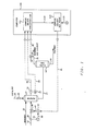
- FIG. 1 A specific control system configuration is set forth is Figure 1 for the sake of illustration.
- the specific control configuration is not a critical feature of the present invention and the invention is applicable to large variety of control configurations which are utilized to manipulate a second process variable so as to maintain the actual value of a first process variable substantially equal to the desired value for the first process variable.
- Lines designated as signal lines in the drawings are electrical or pneumatic in this preferred embodiment.
- the signals provided from any transducer are electrical in form.
- the signals provided from flow sensors will generally be pneumatic in form. Transducing of these signals is not illustrated for the sake of simplicity because it is well known in the art that if a flow is measured in pneumatic form it must be transduced to electrical form if it is to be transmitted in electrical form by a flow transducer. Also, transducing of the signals from analog form to digital form or from digital form to analog form is not illustrated because such transducing is also well known in the art.
- the invention is also applicable to mechanical, hydraulic or other signal means for transmitting information. In almost all control systems some combination of electrical, pneumatic, mechanical or hydraulic signals will be used. However, use of any other type of signal transmission, compatible with the process and equipment in use, is within the scope of the invention.
- a digital computer is used in the preferred embodiment of this invention to calculate the required control signal based on measured process parameters as well as set points supplied to the computer.
- the digital computer is preferably an OPTROL 7000 Process Computer System from Applied Automation, Inc., Bartlesville, Oklahoma.
- Signal lines are also utilized to represent the results of calculations carried out in a digital computer and the term "signal" is utilized to refer to such results.
- signal is used not only to refer to electrical currents or pneumatic pressures but is also used to refer to binary representations of a calculated or measured value.
- the various transducing means used to measure parameters which characterize the process and the various signals generated thereby may take a variety of forms or formats.
- the control elements of the system can be implemented using electrical analog, digital electronic, pneumatic, hydraulic, mechanical or other similar types of equipment or combinations of one or more such equipment types. While the presently preferred embodiment of the invention preferably utilizes a combination of pneumatic final control elements in conjunction with electrical analog signal handling and translation apparatus, the apparatus and method of the invention can be implemented using a variety of specific equipment available to and understood by those skilled in the process control art.
- the format of the various signals can be modified substantially in order to accommodate signal format requirements of the particular installation, safety factors, the physical characteristics of the measuring or control instruments and other similar factors.
- a raw flow measurement signal produced by a differential pressure orifice flow meter would ordinarily exhibit a generally proportional relationship to the square of the actual flow rate.
- Other measuring instruments might produce a signal which is proportional to the measured parameter, and still other transducing means may produce a signal which bears a more complicated, but known, relationship to the measured parameter.
- each signal representative of a measured process parameter or representative of a desired process value will bear a relationship to the measured parameter or desired value which permits designation of a specific measured or desired value by a specific signal value.
- a signal which is representative of a process measurement or desired process value is therefore one from which the information regarding the measured or desired value can be readily retrieved regardless of the exact mathematical relationship between the signal units and the measured or desired process units.
- a polymerization reactor 11 Ethylene is provided to the polymerization reactor 11 through conduit means 12.
- a diluent such as isobutane is provided to the polymerization reactor 11 through conduit means 14 and a catalyst, such as a typical chromium oxide on silica catalyst or a silica-titania catalyst, is provided to the polymerization reactor 11 through conduit means 15.
- the catalyst flowing through conduit means 15 will be introduced periodically into the reactor 11. This is accomplished by use of the catalyst feeder valve 16 which is operably located in conduit means 15.
- the reaction effluent is removed from the reactor 11 through conduit means 17 and is provided to the flash tank 18.
- the reaction effluent will be made up of polyethylene, unreacted ethylene and isobutane.
- the catalyst will generally be contained in the polyethylene.
- the polyethylene is separated from the unreacted ethylene and the isobutane in the flash tank 18.
- Polyethylene is removed from the flash tank 18 through conduit means 19.
- Unreacted ethylene and isobutane are removed from the flash tank 18 through conduit means 21.
- the diluent fed into the reactor does not react but is rather utilized to control solids concentration.
- the set point generation of the present invention is utilized to maintain the actual solids concentration substantially equal to the desired solids concentration by manipulating the flow rate of the diluent. For the particular polymerization process in which the set point generation of the present invention was implemented, the set point for solids in the reactor was 30%. If the solids concentration exceeded 33%, the liquid in the reactor could go solid resulting in a completely plugged reactor which is very difficult to clean.
- Temperature transducer 24 in combination with a temperature sensing device such as a thermocouple, which is operably located pn the reactor 11, provides an output signal 25 which is representative of the temperature in the reactor 11.
- Signal 25 is provided from the temperature transducer 24 as in input to computer 100 and is specifically provided to the compute solids concentration block 111.
- the gamma density gauge 27, which may be a Radiation-density gage as describdd in Perry's Chemical Engineers Handbook, Fifth Edition, Section 22, McGraw-Hill, provides an output signal 29 which is representative of the density of the fluid in the reactor 11. Signal 29 is provided from the density gauge 27 as an input to the compute solids concentration block 111.
- a sample of the fluid flowing to conduit means 21 is provided to the analyzer transducer 34 through conduit means 33.
- the analyzer transducer 34 is preferably a chromatographic analyzer such as the Optichrom 102 chromatographic analyzer from Applied Automation, Inc., Bartlesville, Oklahoma.
- the analyzer transducer 34 provides an output signal 36 which is representative of the concentration of ethylene in the fluid flowing through conduit means 21. Essentially, signal 36 is representative of the concentration of unreacted ethylene removed from the reactor 11.
- Signal 36 is provided from the analyzer transducer 33 as an input to the computer solids concentration block 111.
- the actual solids concentration in the reactor is calculated based on the measured process variables by the conventional technique of using an equation such as that set forth in Proceedings of the 1973 ISA Joint Spring Conference, D. E. Smith, "Control of Polyolefin Reactors Using Calculated Values of Process Variables". It is noted that any technique could be utilized to compute the solids concentration since the technique by which the solids concentration is determined is not a critical feature of the present invention.
- Signal 112 which is representative of the actual solids concentration in the reactor, is provided from the compute solids concentration block 111 as the process variable input to the compute diluent set point block 114 which is essentially a controller having the set point generation features of the present invention.
- Signal 115 which is representative of the desired solids concentration (30% for the ethylene reactor to which the present invention was applied), is provided as the set point input to the compute diluent set point block 114.
- a set point for the flow rate of diluent through conduit means 14 is calculated in the compute diluent set point block 114 as will be more particularly described hereinafter in the description of Figure 2.
- Signal 41 which is representative of the calculated set point for the flow rate of the diluent which will maintain the actual solids concentration represented by signal 112 substantially equal to the desired solids concentration represented by signal 115, is provided as a control output from computer 100 to the flow controller 42.
- Flow transducer 44 in combination with the flow sensor 45, which is operably located in conduit means 14, provides an output signal 46 which is representative of the actual flow rate of the diluent through conduit means 14.
- Signal 46 is provided as the process variable input to the flow controller 42 which is preferably a proportional-integral-derivative controller.
- the flow controller 42 In response to signals 41 and 46, the flow controller 42 provides an output signal 47 which is responsive to the difference between signals 41 and 46.
- Signal 47 is scaled so as to be representative of the position of the control valve 48, which is operably located in conduit means 14, required to maintain the actual flow rate of the diluent through conduit means 14 substantially equal to the desired flgw rate represented by signal 41.
- Signal 47 is provided from the flow controller 42 as the control signal to the control valve 48 and the control valve 48 is manipulated in response thereto.
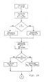
- the first step is to subtract PV (signal 112) from SP (signal 115) to establish the error (E) which is representative of the difference between the actual solids concentration in the reactor 11 as represented by signal 112 and the desired solids concentration as represented by signal 115.
- a proportional term (PE) is then calculated by multiplying the error by a proportionality constant (Kp) which was 250 (!b/hr)/1% change in E.
- Kp proportionality constant
- PI integral term
- K, integral constant which was 50 (Ib/hr)/1% change in E.
- a decision block is utilized to determine whether the error is greater than or equal to zero. This decision is made because the control action will be different depending upon whether the process variable is below the set point or above the set point since the probability of adverse conditions occurring is greater when the process variable is above the set point. If the error is greater than or equal to zero, a more powerful control action is desired and thus a cube of the error is multiplied by the constant K 02 which is equal to 1.2 Kp to derive the power term (PQ). If the error is less than the zero, the error squared multiplied by the constant K Q1 which is equal to .7 Kp is utilized to calculate the power term PQ.
- any desired power could be utilized to calculate the power term PQ. Considerations that are taken into account is the fact that the higher powers will have greater effects as the error goes above 1 but higher powers will also have a more destabilizing effect on the process since they may produce a very large control action in a very short time. Thus, it is desirable to use as low a power as possible while still maintaining the desired control action.
- the derivative of the error as a function of time is calculated.
- the derivative of the error is obtained from an equation of differences applied to a set of five successive observations which yields a corrected or "smooth" derivative at the central point as is illustrated in Wylie, "Advanced Engineering Mathematics", second edition, section 5.6, page 185.
- the specific equation utilized was where:
- the derivative of the error provides an indication of the rate at which the solids concentration in the reactor is changing and also provides an indication of the direction of that change. Thus, if the sign of DZEER is negative, the % solids concentration is decreasing while a positive sign indicates an increasing solids concentration.
- the derivative of the error (DZERR) is again examined to determine if the solids concentration is increasing at a rate greater than DLTDZ2 which was chosen to be +.25%/Hr. If the answer is no, the second derivative term (PD 2 ) is set equal to zero. If the answer is yes, the solids concentration is examined to determine if it is more than 1.5% above the set point (DLTDB2 was chosen to be 1.5(%). Thus, if the error is negative or is less than 1.5%, PD 2 will again be set equal to zero. However, if the error is greater than 1.5% above the set point, significant control action will be taken because the probability that the reactor could go solid is increased since the actual solids concentration is greater than 1.5% above the set point and is increasing.
- the first step in taking this control action is to determine how close the actual solids concentration is to a hard limit on the solids concentration which in the present case was 33%. This is accomplished by subtracting the error from a hard limit on the error (DLTSP1 was 3% since set point was 30%) to determine the margin (MRGN). PD 2 is then calculated by multiplying the derivative of the error by the constant K 02 (chosen to be 350 Ib./1%) and dividing the result by the margin. Thus, as the error approaches the hard limit (DLTSP1), the magnitude of the term MRGN will decrease which will result in an increase in the magnitude of the term PD 2 .
- the derivative term PD is calculated by adding PD 1 and PD 2 .
- the magnitude of signal 41 is then calculated by adding the terms PE, PI, PQ and PD.
- PQ proportional and integral terms
- the magnitude of the derivative term is dependent upon the rate at which the actual solids concentration is increasing or decreasing and upon whether the actual solids concentration is above or below the set point. Essentially, the derivative term will have one value if the solids concentration is increasing but is still below set point plus 1.5% and will have a different value if the solids concentration is increasing and is above the set point plus 1.5%. In the second case, the magnitude of the derivative term increases as the actual solids concentration approaches a hard limit.
- the present invention is not limited to the specific logic illustrated in Figure 2.
- the error could be raised to any suitable power depending on the particular process and in some processes it might be desirable to set the power term equal to zero if the actual value of the process variable is above or below the set point. Also, in some processes, the power term might have a larger magnitude if the actual value of the process variable is below the set point rather than above the set point.
- the manner in which the derivative term, if utilized, is calculated may also vary.
- the important feature of the present invention is that, if the derivative term is utilized, the magnitude of the derivative term will vary depending upon the rate of change of the error and the position of the process variable with respect to the set point.
- the term PD rarely has a value other than zero.
- the use of the derivative term is not required but is preferred to insure that the actual value of the solids concentration does not exceed a high limit such that the reactor would go solid.
- the invention has been described in terms of a preferred embodiment as illustrated in Figures 1 and 2.
- Specific components used in the practice of the invention as illustrated in Figure 1, which have not previously been specified, such as temperature transducer 24, control valve 48, flow controller 42, flow transducer 44 and flow sensor 45 are each well known, commercially available control components such as are described at length in Perry's Chemical Engineer's Handbook 4th. edition, chapter 22, McGraw-Hill.
- the catalyst feeder valve 16 may be a Seiscore ballcheck feeder valve.
Landscapes
- Engineering & Computer Science (AREA)
- Chemical & Material Sciences (AREA)
- Automation & Control Theory (AREA)
- Health & Medical Sciences (AREA)
- Physics & Mathematics (AREA)
- General Physics & Mathematics (AREA)
- Organic Chemistry (AREA)
- Chemical Kinetics & Catalysis (AREA)
- Computer Vision & Pattern Recognition (AREA)
- Polymers & Plastics (AREA)
- Artificial Intelligence (AREA)
- General Engineering & Computer Science (AREA)
- Evolutionary Computation (AREA)
- Medical Informatics (AREA)
- Software Systems (AREA)
- Medicinal Chemistry (AREA)
- Feedback Control In General (AREA)
- Control Of Non-Electrical Variables (AREA)
- Numerical Control (AREA)
- Control Of Eletrric Generators (AREA)
- Paper (AREA)
- Selective Calling Equipment (AREA)
- Polymerisation Methods In General (AREA)
- Making Paper Articles (AREA)
- Vehicle Body Suspensions (AREA)
- Small-Scale Networks (AREA)
Priority Applications (1)
| Application Number | Priority Date | Filing Date | Title |
|---|---|---|---|
| AT83106958T ATE35330T1 (de) | 1982-07-16 | 1983-07-15 | Erzeugung eines sollwertes fuer prozessregelung. |
Applications Claiming Priority (2)
| Application Number | Priority Date | Filing Date | Title |
|---|---|---|---|
| US399109 | 1973-09-20 | ||
| US06/399,109 US4543637A (en) | 1982-07-16 | 1982-07-16 | Generation of a set point for process control |
Publications (3)
| Publication Number | Publication Date |
|---|---|
| EP0099131A2 EP0099131A2 (en) | 1984-01-25 |
| EP0099131A3 EP0099131A3 (en) | 1985-01-23 |
| EP0099131B1 true EP0099131B1 (en) | 1988-06-22 |
Family
ID=23578188
Family Applications (1)
| Application Number | Title | Priority Date | Filing Date |
|---|---|---|---|
| EP83106958A Expired EP0099131B1 (en) | 1982-07-16 | 1983-07-15 | Generation of a set point for process control |
Country Status (8)
| Country | Link |
|---|---|
| US (1) | US4543637A (enExample) |
| EP (1) | EP0099131B1 (enExample) |
| JP (1) | JPS5943403A (enExample) |
| AT (1) | ATE35330T1 (enExample) |
| CA (1) | CA1215448A (enExample) |
| DE (1) | DE3377168D1 (enExample) |
| ES (1) | ES524146A0 (enExample) |
| NO (1) | NO166982C (enExample) |
Families Citing this family (24)
| Publication number | Priority date | Publication date | Assignee | Title |
|---|---|---|---|---|
| US5190730A (en) * | 1982-11-17 | 1993-03-02 | Chemical Research & Licensing Company | Reactor for exothermic reactions |
| US4668473A (en) * | 1983-04-25 | 1987-05-26 | The Babcock & Wilcox Company | Control system for ethylene polymerization reactor |
| GB8401630D0 (en) * | 1984-01-21 | 1984-02-22 | Interox Chemicals Ltd | Analysing and control |
| US4989157A (en) * | 1985-01-22 | 1991-01-29 | The Boeing Company | Automated chemical milling controller |
| US4727472A (en) * | 1986-03-31 | 1988-02-23 | Motorola, Inc. | Servo control system for transmission shaft speed control |
| CA2023745A1 (en) * | 1989-11-27 | 1991-05-28 | Kelly E. Tormaschy | Control of polymerization reaction |
| US5077029A (en) * | 1990-07-23 | 1991-12-31 | Union Carbide Industrial Gases Technology Corporation | Membrane/deoxo control method and system |
| JPH04115530A (ja) * | 1990-09-05 | 1992-04-16 | Fujitsu Ltd | 半導体装置の製造方法 |
| US5499193A (en) * | 1991-04-17 | 1996-03-12 | Takeda Chemical Industries, Ltd. | Automated synthesis apparatus and method of controlling the apparatus |
| US5262963A (en) * | 1991-06-28 | 1993-11-16 | Imc Fertilizer, Inc. | Automatic control system for phosphoric acid plant |
| US5188812A (en) * | 1991-11-13 | 1993-02-23 | Imc Fertilizer, Inc. | Automatic control system for a phosacid attack tank and filter |
| US5387659A (en) * | 1993-02-08 | 1995-02-07 | Phillips Petroleum Company | Flash gas sampling for polymerization reactions |
| US5395603A (en) * | 1993-04-21 | 1995-03-07 | Imc Fertilizer, Inc. | Automatic control system for a chemical process, especially a wet process phosphoric acid plant |
| FR2790760A1 (fr) * | 1999-03-12 | 2000-09-15 | Bp Chemicals Snc | Procede de polymerisation de l'isobutene |
| FR2794757B1 (fr) | 1999-06-11 | 2002-06-14 | Bp Chemicals Snc | Procede de polymerisation de l'isobutene |
| US6389364B1 (en) * | 1999-07-10 | 2002-05-14 | Mykrolis Corporation | System and method for a digital mass flow controller |
| JP2003506495A (ja) * | 1999-08-03 | 2003-02-18 | ユニオン・カーバイド・ケミカルズ・アンド・プラスティックス・テクノロジー・コーポレイション | 重合用流動床反応器における局部的非流動化およびチャネリングの検出および修正の方法 |
| FR2800379A1 (fr) * | 1999-10-29 | 2001-05-04 | Bp Chemicals Snc | Procede de copolymerisation en phase gazeuse d'au moins deux alpha-olefines ayant de 2 a 12 atomes de carbone |
| FR2810325A1 (fr) | 2000-06-16 | 2001-12-21 | Bp Chemicals Snc | Procede de polymerisation de l'isobutene |
| US8093341B2 (en) * | 2004-10-28 | 2012-01-10 | Dow Global Technologies Llc | Method of controlling a polymerization reactor |
| KR101155244B1 (ko) * | 2010-02-04 | 2012-06-13 | 엘지전자 주식회사 | 시운전 제어 장치 및 그 방법 |
| US9222685B2 (en) | 2010-07-15 | 2015-12-29 | Hill-Rom Services, Inc. | Method and system for controlling evaporative and heat withdrawal performance of an occupant support surface |
| EP2868375A1 (en) * | 2013-10-31 | 2015-05-06 | Borealis AG | A method for producing an olefin polymerization catalyst |
| US10455765B2 (en) * | 2017-08-31 | 2019-10-29 | Cnh Industrial America Llc | Method and system for controlling the height of agricultural implement relative to the ground |
Family Cites Families (17)
| Publication number | Priority date | Publication date | Assignee | Title |
|---|---|---|---|---|
| US30564A (en) * | 1860-11-06 | Canal and bivek lock | ||
| US3621357A (en) * | 1968-10-25 | 1971-11-16 | Tokyo Shibaura Electric Co | Apparatus processing pulse numbers for use in a pid digital control system |
| US3591783A (en) * | 1969-02-24 | 1971-07-06 | Exxon Research Engineering Co | Automatic control of fluid catalytic cracking units |
| US3636326A (en) * | 1970-07-24 | 1972-01-18 | Phillips Petroleum Co | Control system for polymerization reactors |
| US3770946A (en) * | 1971-02-25 | 1973-11-06 | Leeds & Northrup Co | Method for automatic control with time varying tuning |
| US3748565A (en) * | 1971-10-22 | 1973-07-24 | Singer Co | Predictive position feedback controller for web guide control system |
| US3800288A (en) * | 1972-02-24 | 1974-03-26 | Foxboro Co | Computer-directed process control system with crt display |
| US3878379A (en) * | 1972-08-14 | 1975-04-15 | Allied Chem | Polymer intrinsic viscosity control |
| GB1416401A (en) * | 1973-03-06 | 1975-12-03 | Rolls Royce | Control systems |
| GB1463067A (en) | 1973-09-22 | 1977-02-02 | Ferranti Ltd | Servo systems |
| GB1603825A (en) * | 1977-05-17 | 1981-12-02 | Jones K R | Three term (pid) controllers |
| GB2004089B (en) * | 1977-07-16 | 1982-01-13 | Rolls Royce | Control system |
| US4250543A (en) * | 1978-07-21 | 1981-02-10 | Scans Associates, Inc. | Method of controlling production processes and apparatus therefor |
| US4265263A (en) * | 1979-08-28 | 1981-05-05 | Phillips Petroleum Company | Non-linear level controller |
| US4328549A (en) * | 1980-01-11 | 1982-05-04 | Olin Corporation | Process flow computer control system |
| US4346433A (en) * | 1980-03-11 | 1982-08-24 | Phillips Petroleum Company | Process control |
| JPS57199004A (en) * | 1981-06-01 | 1982-12-06 | Toshiba Corp | Sample value adaptive process controller |
-
1982
- 1982-07-16 US US06/399,109 patent/US4543637A/en not_active Expired - Lifetime
-
1983
- 1983-07-01 JP JP58120137A patent/JPS5943403A/ja active Granted
- 1983-07-11 CA CA000432213A patent/CA1215448A/en not_active Expired
- 1983-07-15 NO NO832577A patent/NO166982C/no unknown
- 1983-07-15 DE DE8383106958T patent/DE3377168D1/de not_active Expired
- 1983-07-15 ES ES524146A patent/ES524146A0/es active Granted
- 1983-07-15 AT AT83106958T patent/ATE35330T1/de not_active IP Right Cessation
- 1983-07-15 EP EP83106958A patent/EP0099131B1/en not_active Expired
Also Published As
| Publication number | Publication date |
|---|---|
| ES8501897A1 (es) | 1984-12-01 |
| NO166982B (no) | 1991-06-10 |
| JPS5943403A (ja) | 1984-03-10 |
| CA1215448A (en) | 1986-12-16 |
| DE3377168D1 (en) | 1988-07-28 |
| ATE35330T1 (de) | 1988-07-15 |
| EP0099131A2 (en) | 1984-01-25 |
| EP0099131A3 (en) | 1985-01-23 |
| JPH0113121B2 (enExample) | 1989-03-03 |
| NO166982C (no) | 1991-09-18 |
| ES524146A0 (es) | 1984-12-01 |
| US4543637A (en) | 1985-09-24 |
| NO832577L (no) | 1984-01-17 |
Similar Documents
| Publication | Publication Date | Title |
|---|---|---|
| EP0099131B1 (en) | Generation of a set point for process control | |
| US5455314A (en) | Method for controlling removal of polymerization reaction effluent | |
| US4457266A (en) | Boiler control | |
| US4249908A (en) | Temperature control of exothermic reactions | |
| US4386623A (en) | Nonlinear control of liquid level | |
| US4676870A (en) | Automatic control of a multiple-effect evaporator | |
| US4249907A (en) | Temperature control of exothermic reactions | |
| US4979091A (en) | Control of a blending system | |
| US4619901A (en) | Control of polymerization reaction | |
| US4578151A (en) | Reid Vapor Pressure determination and control in fractional distillation | |
| US4290110A (en) | Temperature control for a reactor | |
| US4473490A (en) | Control of a reforming furnace | |
| US3728085A (en) | Predictive control system for polymerizing ethylene | |
| US4482969A (en) | Control of an alkylation reactor | |
| EP0028023B1 (en) | Apparatus and method for controlling the reactor temperature profile and the reactants feed stream | |
| US4555309A (en) | Control of a fractional distillation process | |
| US4559785A (en) | Boiler control | |
| US4435192A (en) | Control of a H2 S absorber | |
| US4473442A (en) | Acid regenerator control | |
| US4371426A (en) | Control of a fractional distillation process | |
| US4558423A (en) | Utilization of an ASTM end point temperature for controlling a fractional distillation process | |
| US4557686A (en) | Control of the flow of fuel to multiple burners | |
| US4367354A (en) | Temperature control of a selective hydrogenation process | |
| US4356863A (en) | Temperature control for preheating a crude oil feedstock | |
| US4772298A (en) | Control of a H2 S absorber |
Legal Events
| Date | Code | Title | Description |
|---|---|---|---|
| PUAI | Public reference made under article 153(3) epc to a published international application that has entered the european phase |
Free format text: ORIGINAL CODE: 0009012 |
|
| AK | Designated contracting states |
Designated state(s): AT BE CH DE FR GB IT LI LU NL SE |
|
| PUAL | Search report despatched |
Free format text: ORIGINAL CODE: 0009013 |
|
| AK | Designated contracting states |
Designated state(s): AT BE CH DE FR GB IT LI LU NL SE |
|
| 17P | Request for examination filed |
Effective date: 19850705 |
|
| 17Q | First examination report despatched |
Effective date: 19870407 |
|
| GRAA | (expected) grant |
Free format text: ORIGINAL CODE: 0009210 |
|
| AK | Designated contracting states |
Kind code of ref document: B1 Designated state(s): AT BE CH DE FR GB IT LI LU NL SE |
|
| REF | Corresponds to: |
Ref document number: 35330 Country of ref document: AT Date of ref document: 19880715 Kind code of ref document: T |
|
| ITF | It: translation for a ep patent filed | ||
| REF | Corresponds to: |
Ref document number: 3377168 Country of ref document: DE Date of ref document: 19880728 |
|
| ET | Fr: translation filed | ||
| PLBE | No opposition filed within time limit |
Free format text: ORIGINAL CODE: 0009261 |
|
| STAA | Information on the status of an ep patent application or granted ep patent |
Free format text: STATUS: NO OPPOSITION FILED WITHIN TIME LIMIT |
|
| 26N | No opposition filed | ||
| ITTA | It: last paid annual fee | ||
| PGFP | Annual fee paid to national office [announced via postgrant information from national office to epo] |
Ref country code: GB Payment date: 19920507 Year of fee payment: 10 |
|
| PGFP | Annual fee paid to national office [announced via postgrant information from national office to epo] |
Ref country code: CH Payment date: 19920603 Year of fee payment: 10 |
|
| PGFP | Annual fee paid to national office [announced via postgrant information from national office to epo] |
Ref country code: AT Payment date: 19920615 Year of fee payment: 10 |
|
| PGFP | Annual fee paid to national office [announced via postgrant information from national office to epo] |
Ref country code: FR Payment date: 19920617 Year of fee payment: 10 |
|
| PGFP | Annual fee paid to national office [announced via postgrant information from national office to epo] |
Ref country code: SE Payment date: 19920622 Year of fee payment: 10 |
|
| PGFP | Annual fee paid to national office [announced via postgrant information from national office to epo] |
Ref country code: DE Payment date: 19920629 Year of fee payment: 10 |
|
| PGFP | Annual fee paid to national office [announced via postgrant information from national office to epo] |
Ref country code: LU Payment date: 19920701 Year of fee payment: 10 |
|
| PGFP | Annual fee paid to national office [announced via postgrant information from national office to epo] |
Ref country code: BE Payment date: 19920710 Year of fee payment: 10 |
|
| PGFP | Annual fee paid to national office [announced via postgrant information from national office to epo] |
Ref country code: NL Payment date: 19920731 Year of fee payment: 10 |
|
| EPTA | Lu: last paid annual fee | ||
| PG25 | Lapsed in a contracting state [announced via postgrant information from national office to epo] |
Ref country code: LU Free format text: LAPSE BECAUSE OF NON-PAYMENT OF DUE FEES Effective date: 19930715 Ref country code: GB Effective date: 19930715 Ref country code: AT Effective date: 19930715 |
|
| PG25 | Lapsed in a contracting state [announced via postgrant information from national office to epo] |
Ref country code: SE Effective date: 19930716 |
|
| PG25 | Lapsed in a contracting state [announced via postgrant information from national office to epo] |
Ref country code: LI Effective date: 19930731 Ref country code: CH Effective date: 19930731 Ref country code: BE Effective date: 19930731 |
|
| BERE | Be: lapsed |
Owner name: PHILLIPS PETROLEUM CY Effective date: 19930731 |
|
| PG25 | Lapsed in a contracting state [announced via postgrant information from national office to epo] |
Ref country code: NL Effective date: 19940201 |
|
| GBPC | Gb: european patent ceased through non-payment of renewal fee |
Effective date: 19930715 |
|
| NLV4 | Nl: lapsed or anulled due to non-payment of the annual fee | ||
| PG25 | Lapsed in a contracting state [announced via postgrant information from national office to epo] |
Ref country code: FR Effective date: 19940331 |
|
| REG | Reference to a national code |
Ref country code: CH Ref legal event code: PL |
|
| PG25 | Lapsed in a contracting state [announced via postgrant information from national office to epo] |
Ref country code: DE Effective date: 19940401 |
|
| REG | Reference to a national code |
Ref country code: FR Ref legal event code: ST |
|
| EUG | Se: european patent has lapsed |
Ref document number: 83106958.8 Effective date: 19940210 |