EP0099112B1 - Raumdiversity-System - Google Patents
Raumdiversity-System Download PDFInfo
- Publication number
- EP0099112B1 EP0099112B1 EP83106831A EP83106831A EP0099112B1 EP 0099112 B1 EP0099112 B1 EP 0099112B1 EP 83106831 A EP83106831 A EP 83106831A EP 83106831 A EP83106831 A EP 83106831A EP 0099112 B1 EP0099112 B1 EP 0099112B1
- Authority
- EP
- European Patent Office
- Prior art keywords
- output
- signal
- error detector
- antenna
- oscillator
- Prior art date
- Legal status (The legal status is an assumption and is not a legal conclusion. Google has not performed a legal analysis and makes no representation as to the accuracy of the status listed.)
- Expired
Links
- 230000005540 biological transmission Effects 0.000 claims description 5
- 238000009499 grossing Methods 0.000 claims description 3
- 230000010363 phase shift Effects 0.000 description 6
- 238000000034 method Methods 0.000 description 3
- 238000010586 diagram Methods 0.000 description 2
- 230000010354 integration Effects 0.000 description 2
- 230000004048 modification Effects 0.000 description 2
- 238000012986 modification Methods 0.000 description 2
- 239000002131 composite material Substances 0.000 description 1
- 238000010276 construction Methods 0.000 description 1
- 230000007423 decrease Effects 0.000 description 1
Images


Classifications
-
- H—ELECTRICITY
- H04—ELECTRIC COMMUNICATION TECHNIQUE
- H04B—TRANSMISSION
- H04B1/00—Details of transmission systems, not covered by a single one of groups H04B3/00 - H04B13/00; Details of transmission systems not characterised by the medium used for transmission
- H04B1/06—Receivers
- H04B1/10—Means associated with receiver for limiting or suppressing noise or interference
- H04B1/12—Neutralising, balancing, or compensation arrangements
- H04B1/123—Neutralising, balancing, or compensation arrangements using adaptive balancing or compensation means
- H04B1/126—Neutralising, balancing, or compensation arrangements using adaptive balancing or compensation means having multiple inputs, e.g. auxiliary antenna for receiving interfering signal
-
- H—ELECTRICITY
- H04—ELECTRIC COMMUNICATION TECHNIQUE
- H04L—TRANSMISSION OF DIGITAL INFORMATION, e.g. TELEGRAPHIC COMMUNICATION
- H04L1/00—Arrangements for detecting or preventing errors in the information received
- H04L1/02—Arrangements for detecting or preventing errors in the information received by diversity reception
- H04L1/06—Arrangements for detecting or preventing errors in the information received by diversity reception using space diversity
Definitions
- the present invention relates to a space diversity system for the transmission of digital microwaves.
- composite outputs are provided either by a method relying on inphase combination or a method relying on switching.
- the former is predominant today because the latter is unsuitable for digital transmission systems due to a phase difference between two antenna outputs which would cause switching to bring discontinuity into phases.
- the system comprises a variable phase shifter for controlling the output phase of the second antenna, a demodulator for receiving the combined output of the two antennas, an identification circuit for identifying a digital signal output from the demodulator, an error detector for detecting a magnitude of a difference between an input signal and an output signal of the identification circuit, an oscillator for generating a signal having a short period, a correlation circuit for determining a correlation between an output of the oscillator and an output of the error detector, at least an integrator for integrating the output of the correlation circuit or a low-pass filter for smoothing the output of the correlation circuit, and means for controlling the phase shifter in such a manner as to minimize the output of the error detector by adding the output of the integrator or the low-pass filter to a signal derived from the output of the oscillator and supplying the sum to the phase shifter as a control signal.
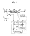
- the space diversity system includes antennas 10 and 12, a combining circuit 14, a variable phase shifter 16, mixers 18 and 20, and an oscillator 21 which are common in construction to those described in the previously mentioned U.S. Patent 4,326,294.
- a demodulator 22 demodulates a signal prepared by combining outputs of the antennas 10 and 12.
- the digital output of the demodulator 22 is fed to an identification circuit 24 as well as to an error detector 26. While the identification circuit 24 identifies the digital signal, the error detector 26 determines the absolute value of an error or difference e between the input and the output of the identification circuit 24.
- the output Jet of the error detector 26 increases with an increase in interference wave and with an increase in noise.
- the error detector output !ei grows extremely large due to an increase in noise.
- the regular identified output of the demodulator 22 appears at a terminal 28.
- the output of the demodulator 22 is a baseband signal identical with a signal which was sent out from a transmitter.
- PSK 4-phase shift keying
- phase control on the variable phase shifter 16 is performed in a direction for minimizing the output of the error detector 26 as described above, desirable controls will occur for all the signal input conditions at the antennas 10 and 12.
- phase shift ⁇ s is not optimized and, therefore, includes a deviation ed (rad) as expressed by
- the control section 30 comprises an oscillator 32 for generating the perturbation ⁇ o ⁇ sin ⁇ o t, an integrator 34 for control, and a polarity reversing circuit 36.
- An adder 38 functions to add a perturbance signal to a control signal for a voltage controlled oscillator.
- a correlation circuit 40 comprises a multiplier 42 and an integrator 44 and serves to determine a correlation R between the perturbance signal and the output of the error detector 26.
- the integrator 44 does not constitute any essential part of the circuit and may be omitted, if desired.
- the output of the adder 38 is the control signal for controlling the phase of the phase shifter 16.
- the present invention provides a space diversity system which minimizes identification errors by the way the variable phase shifter 16 is controlled by the error detector 26.
- Figure 4 shows a modified space diversity system shown in Figure 1 where the perturbation amplitude so in the perturbation ⁇ o . sinw o t is controlled according to the output level of the error detector 26. If the output level of the error detector 26 is large, the perturbation amplitude so is set large so as to detect the correlation R easily. On the other hand, if it is an inverse case, the so is set small so that this perturbation may not generate a large signal output jitter.
- This function is performed by a combination of a lowpass filter 45 and a multiplier 46.
- the lowpass filter 45 smooths the output of the error detector 26 and makes the output proportional to the error level.
- the multiplier 46 modifies the oscillator output according to the output of the low pass filter 45.
Landscapes
- Engineering & Computer Science (AREA)
- Computer Networks & Wireless Communication (AREA)
- Signal Processing (AREA)
- Radio Transmission System (AREA)
Claims (2)
Applications Claiming Priority (2)
| Application Number | Priority Date | Filing Date | Title |
|---|---|---|---|
| JP122716/82 | 1982-07-14 | ||
| JP57122716A JPS5913442A (ja) | 1982-07-14 | 1982-07-14 | 信号分散最小型スペ−ス・ダイバ−シテイ−装置 |
Publications (3)
| Publication Number | Publication Date |
|---|---|
| EP0099112A2 EP0099112A2 (de) | 1984-01-25 |
| EP0099112A3 EP0099112A3 (en) | 1984-03-07 |
| EP0099112B1 true EP0099112B1 (de) | 1985-11-21 |
Family
ID=14842821
Family Applications (1)
| Application Number | Title | Priority Date | Filing Date |
|---|---|---|---|
| EP83106831A Expired EP0099112B1 (de) | 1982-07-14 | 1983-07-12 | Raumdiversity-System |
Country Status (6)
| Country | Link |
|---|---|
| US (1) | US4498885A (de) |
| EP (1) | EP0099112B1 (de) |
| JP (1) | JPS5913442A (de) |
| AU (1) | AU563228B2 (de) |
| CA (1) | CA1210073A (de) |
| DE (1) | DE3361292D1 (de) |
Families Citing this family (13)
| Publication number | Priority date | Publication date | Assignee | Title |
|---|---|---|---|---|
| JPS59230334A (ja) * | 1983-06-13 | 1984-12-24 | Fujitsu Ltd | 空間ダイバ−シチ受信方式 |
| DE3510580A1 (de) * | 1985-03-23 | 1986-09-25 | Blaupunkt-Werke Gmbh, 3200 Hildesheim | Verfahren und schaltungsanordnung zur verbesserung des empfangs von radiowellen |
| US4736455A (en) * | 1985-12-23 | 1988-04-05 | Nippon Telegraph And Telephone Corporation | Interference cancellation system |
| DE3641109A1 (de) * | 1986-12-02 | 1988-08-25 | Lindenmeier Heinz | Signaldiversity-anlage fuer den mobilen empfang |
| DE4012199C2 (de) * | 1990-04-14 | 1994-03-17 | Ant Nachrichtentech | Verfahren und Anordnung zum Empfang mehrerer Signale nach dem Diversityprinzip |
| US5722049A (en) * | 1995-12-05 | 1998-02-24 | Ericsson Inc. | Mobile-link system for a radio communication system wherein diversity combining is performed only for edge/boundary zone signals and not for central zone signals |
| US7046653B2 (en) * | 1998-05-01 | 2006-05-16 | Jan Nigrin | Diversity communication system and method of operation thereof |
| US6704557B1 (en) * | 1999-04-22 | 2004-03-09 | Lucent Technologies Inc. | System and method for protecting a receiver from jamming interference |
| KR100742172B1 (ko) * | 1999-09-08 | 2007-07-25 | 톰슨 라이센싱 | 텔레비전 신호에서 다중 경로 왜곡을 저감하기 위한 방법및 장치 |
| US6911947B1 (en) | 1999-09-08 | 2005-06-28 | Thomson Licensing S.A. | Method and apparatus for reducing multipath distortion in a television signal |
| US7447284B2 (en) * | 2003-03-28 | 2008-11-04 | Freescale Semiconductor, Inc. | Method and apparatus for signal noise control |
| CN103190084B (zh) | 2011-10-28 | 2016-04-13 | 华为技术有限公司 | 一种全双工通信装置和方法 |
| US9444505B2 (en) | 2014-04-11 | 2016-09-13 | Broadcom Corporation | System and method for frequency reuse for wireless point-to-point backhaul |
Family Cites Families (5)
| Publication number | Priority date | Publication date | Assignee | Title |
|---|---|---|---|---|
| US4326294A (en) * | 1979-02-13 | 1982-04-20 | Nippon Telegraph & Telephone Public Corporation | Space diversity reception system having compensation means of multipath effect |
| US4278978A (en) * | 1979-09-18 | 1981-07-14 | Nasa | Baseband signal combiner for large aperture antenna array |
| DE3110602C2 (de) * | 1980-03-28 | 1985-07-04 | Nippon Telegraph & Telephone Public Corp., Tokio/Tokyo | Interferenz-Kompensationssystem |
| JPS5792931A (en) * | 1980-11-28 | 1982-06-09 | Fujitsu Ltd | Space diversity receiving device |
| US4373210A (en) * | 1981-03-27 | 1983-02-08 | Bell Telephone Laboratories, Incorporated | Space diversity combiner |
-
1982
- 1982-07-14 JP JP57122716A patent/JPS5913442A/ja active Pending
-
1983
- 1983-07-11 US US06/512,649 patent/US4498885A/en not_active Expired - Lifetime
- 1983-07-12 DE DE8383106831T patent/DE3361292D1/de not_active Expired
- 1983-07-12 EP EP83106831A patent/EP0099112B1/de not_active Expired
- 1983-07-13 AU AU16809/83A patent/AU563228B2/en not_active Ceased
- 1983-07-13 CA CA000432387A patent/CA1210073A/en not_active Expired
Also Published As
| Publication number | Publication date |
|---|---|
| EP0099112A3 (en) | 1984-03-07 |
| US4498885A (en) | 1985-02-12 |
| EP0099112A2 (de) | 1984-01-25 |
| AU563228B2 (en) | 1987-07-02 |
| DE3361292D1 (en) | 1986-01-02 |
| AU1680983A (en) | 1984-01-19 |
| CA1210073A (en) | 1986-08-19 |
| JPS5913442A (ja) | 1984-01-24 |
Similar Documents
| Publication | Publication Date | Title |
|---|---|---|
| EP0099112B1 (de) | Raumdiversity-System | |
| US4484337A (en) | Carrier wave regenerating circuit | |
| US5448602A (en) | Diversity radio receiver | |
| EP1225711B1 (de) | Kreuzpolarisationsinterferenzkompensator und Verfahren zur Kompensation der Kreuzpolarisationsinterferenz | |
| CA2173530C (en) | Modulation and demodulation method, modulator and demodulator | |
| EP0718971A2 (de) | Empfänger mit automatischer Frequenznachregelung | |
| US4079379A (en) | Null steering apparatus for a multiple antenna array | |
| EP0140440A2 (de) | Datenempfänger | |
| CA1230649A (en) | Interference canceller loop having automatic nulling of the loop phase shift for use in a reception system | |
| EP0120416B1 (de) | Demodulator mit einer Schaltung zur automatischen Verstärkungsregelung | |
| US3109143A (en) | Synchronous demodulator for radiotelegraph signals with phase lock for local oscillator during both mark and space | |
| US4477913A (en) | Automatic equalizer apparatus | |
| GB1580921A (en) | Phase demodulator with offset frequency reference oscillator | |
| US5432819A (en) | DPSK communications with Doppler compensation | |
| US5787124A (en) | Quadrature detector and amplitude error correction method for quadrature detector | |
| EP0099113B2 (de) | Raumdiversity-System mit Störungsauslöschung | |
| US4881049A (en) | QAM modulator/demodulator | |
| JPS5918900B2 (ja) | 復調装置 | |
| US4099130A (en) | Phase synchronizing circuit | |
| EP0940005B1 (de) | Verfahren und gerät zur verwendung mit phasenmodulierten signalen | |
| US5982200A (en) | Costas loop carrier recovery circuit using square-law circuits | |
| US6246730B1 (en) | Method and arrangement for differentially detecting an MPSK signal using a plurality of past symbol data | |
| EP0293828B1 (de) | Schaltungsanordnung zum Demodulieren DSB-modulierter Signale und Verfahren dafür | |
| EP0221476B1 (de) | Einrichtung zur Kompensation des Fernsehinterferenzschwundes nach Phase und Amplitude | |
| JP2734137B2 (ja) | 両偏波受信システム |
Legal Events
| Date | Code | Title | Description |
|---|---|---|---|
| PUAI | Public reference made under article 153(3) epc to a published international application that has entered the european phase |
Free format text: ORIGINAL CODE: 0009012 |
|
| PUAL | Search report despatched |
Free format text: ORIGINAL CODE: 0009013 |
|
| AK | Designated contracting states |
Designated state(s): DE FR GB |
|
| AK | Designated contracting states |
Designated state(s): DE FR GB |
|
| 17P | Request for examination filed |
Effective date: 19840227 |
|
| GRAA | (expected) grant |
Free format text: ORIGINAL CODE: 0009210 |
|
| AK | Designated contracting states |
Designated state(s): DE FR GB |
|
| ET | Fr: translation filed | ||
| REF | Corresponds to: |
Ref document number: 3361292 Country of ref document: DE Date of ref document: 19860102 |
|
| PLBE | No opposition filed within time limit |
Free format text: ORIGINAL CODE: 0009261 |
|
| STAA | Information on the status of an ep patent application or granted ep patent |
Free format text: STATUS: NO OPPOSITION FILED WITHIN TIME LIMIT |
|
| 26N | No opposition filed | ||
| PGFP | Annual fee paid to national office [announced via postgrant information from national office to epo] |
Ref country code: GB Payment date: 19950707 Year of fee payment: 13 |
|
| PGFP | Annual fee paid to national office [announced via postgrant information from national office to epo] |
Ref country code: FR Payment date: 19950725 Year of fee payment: 13 |
|
| PGFP | Annual fee paid to national office [announced via postgrant information from national office to epo] |
Ref country code: DE Payment date: 19950929 Year of fee payment: 13 |
|
| PG25 | Lapsed in a contracting state [announced via postgrant information from national office to epo] |
Ref country code: GB Effective date: 19960712 |
|
| GBPC | Gb: european patent ceased through non-payment of renewal fee |
Effective date: 19960712 |
|
| PG25 | Lapsed in a contracting state [announced via postgrant information from national office to epo] |
Ref country code: FR Effective date: 19970328 |
|
| PG25 | Lapsed in a contracting state [announced via postgrant information from national office to epo] |
Ref country code: DE Effective date: 19970402 |
|
| REG | Reference to a national code |
Ref country code: FR Ref legal event code: ST |