EP0099083A2 - Réservoir d'énergie oléopneumatique pour l'accumulation de l'énergie de freinage récupérée sur un véhicule - Google Patents
Réservoir d'énergie oléopneumatique pour l'accumulation de l'énergie de freinage récupérée sur un véhicule Download PDFInfo
- Publication number
- EP0099083A2 EP0099083A2 EP83106727A EP83106727A EP0099083A2 EP 0099083 A2 EP0099083 A2 EP 0099083A2 EP 83106727 A EP83106727 A EP 83106727A EP 83106727 A EP83106727 A EP 83106727A EP 0099083 A2 EP0099083 A2 EP 0099083A2
- Authority
- EP
- European Patent Office
- Prior art keywords
- high pressure
- vehicle
- tank according
- envelope
- low pressure
- Prior art date
- Legal status (The legal status is an assumption and is not a legal conclusion. Google has not performed a legal analysis and makes no representation as to the accuracy of the status listed.)
- Granted
Links
Images


Classifications
-
- B—PERFORMING OPERATIONS; TRANSPORTING
- B60—VEHICLES IN GENERAL
- B60K—ARRANGEMENT OR MOUNTING OF PROPULSION UNITS OR OF TRANSMISSIONS IN VEHICLES; ARRANGEMENT OR MOUNTING OF PLURAL DIVERSE PRIME-MOVERS IN VEHICLES; AUXILIARY DRIVES FOR VEHICLES; INSTRUMENTATION OR DASHBOARDS FOR VEHICLES; ARRANGEMENTS IN CONNECTION WITH COOLING, AIR INTAKE, GAS EXHAUST OR FUEL SUPPLY OF PROPULSION UNITS IN VEHICLES
- B60K6/00—Arrangement or mounting of plural diverse prime-movers for mutual or common propulsion, e.g. hybrid propulsion systems comprising electric motors and internal combustion engines ; Control systems therefor, i.e. systems controlling two or more prime movers, or controlling one of these prime movers and any of the transmission, drive or drive units Informative references: mechanical gearings with secondary electric drive F16H3/72; arrangements for handling mechanical energy structurally associated with the dynamo-electric machine H02K7/00; machines comprising structurally interrelated motor and generator parts H02K51/00; dynamo-electric machines not otherwise provided for in H02K see H02K99/00
- B60K6/08—Prime-movers comprising combustion engines and mechanical or fluid energy storing means
- B60K6/12—Prime-movers comprising combustion engines and mechanical or fluid energy storing means by means of a chargeable fluidic accumulator
-
- B—PERFORMING OPERATIONS; TRANSPORTING
- B60—VEHICLES IN GENERAL
- B60T—VEHICLE BRAKE CONTROL SYSTEMS OR PARTS THEREOF; BRAKE CONTROL SYSTEMS OR PARTS THEREOF, IN GENERAL; ARRANGEMENT OF BRAKING ELEMENTS ON VEHICLES IN GENERAL; PORTABLE DEVICES FOR PREVENTING UNWANTED MOVEMENT OF VEHICLES; VEHICLE MODIFICATIONS TO FACILITATE COOLING OF BRAKES
- B60T1/00—Arrangements of braking elements, i.e. of those parts where braking effect occurs specially for vehicles
- B60T1/02—Arrangements of braking elements, i.e. of those parts where braking effect occurs specially for vehicles acting by retarding wheels
- B60T1/10—Arrangements of braking elements, i.e. of those parts where braking effect occurs specially for vehicles acting by retarding wheels by utilising wheel movement for accumulating energy, e.g. driving air compressors
-
- F—MECHANICAL ENGINEERING; LIGHTING; HEATING; WEAPONS; BLASTING
- F16—ENGINEERING ELEMENTS AND UNITS; GENERAL MEASURES FOR PRODUCING AND MAINTAINING EFFECTIVE FUNCTIONING OF MACHINES OR INSTALLATIONS; THERMAL INSULATION IN GENERAL
- F16D—COUPLINGS FOR TRANSMITTING ROTATION; CLUTCHES; BRAKES
- F16D61/00—Brakes with means for making the energy absorbed available for use
-
- Y—GENERAL TAGGING OF NEW TECHNOLOGICAL DEVELOPMENTS; GENERAL TAGGING OF CROSS-SECTIONAL TECHNOLOGIES SPANNING OVER SEVERAL SECTIONS OF THE IPC; TECHNICAL SUBJECTS COVERED BY FORMER USPC CROSS-REFERENCE ART COLLECTIONS [XRACs] AND DIGESTS
- Y02—TECHNOLOGIES OR APPLICATIONS FOR MITIGATION OR ADAPTATION AGAINST CLIMATE CHANGE
- Y02T—CLIMATE CHANGE MITIGATION TECHNOLOGIES RELATED TO TRANSPORTATION
- Y02T10/00—Road transport of goods or passengers
- Y02T10/60—Other road transportation technologies with climate change mitigation effect
- Y02T10/62—Hybrid vehicles
-
- Y—GENERAL TAGGING OF NEW TECHNOLOGICAL DEVELOPMENTS; GENERAL TAGGING OF CROSS-SECTIONAL TECHNOLOGIES SPANNING OVER SEVERAL SECTIONS OF THE IPC; TECHNICAL SUBJECTS COVERED BY FORMER USPC CROSS-REFERENCE ART COLLECTIONS [XRACs] AND DIGESTS
- Y10—TECHNICAL SUBJECTS COVERED BY FORMER USPC
- Y10T—TECHNICAL SUBJECTS COVERED BY FORMER US CLASSIFICATION
- Y10T137/00—Fluid handling
- Y10T137/4673—Plural tanks or compartments with parallel flow
- Y10T137/474—With housings, supports or stacking arrangements
-
- Y—GENERAL TAGGING OF NEW TECHNOLOGICAL DEVELOPMENTS; GENERAL TAGGING OF CROSS-SECTIONAL TECHNOLOGIES SPANNING OVER SEVERAL SECTIONS OF THE IPC; TECHNICAL SUBJECTS COVERED BY FORMER USPC CROSS-REFERENCE ART COLLECTIONS [XRACs] AND DIGESTS
- Y10—TECHNICAL SUBJECTS COVERED BY FORMER USPC
- Y10T—TECHNICAL SUBJECTS COVERED BY FORMER US CLASSIFICATION
- Y10T137/00—Fluid handling
- Y10T137/4673—Plural tanks or compartments with parallel flow
- Y10T137/4824—Tank within tank
-
- Y—GENERAL TAGGING OF NEW TECHNOLOGICAL DEVELOPMENTS; GENERAL TAGGING OF CROSS-SECTIONAL TECHNOLOGIES SPANNING OVER SEVERAL SECTIONS OF THE IPC; TECHNICAL SUBJECTS COVERED BY FORMER USPC CROSS-REFERENCE ART COLLECTIONS [XRACs] AND DIGESTS
- Y10—TECHNICAL SUBJECTS COVERED BY FORMER USPC
- Y10T—TECHNICAL SUBJECTS COVERED BY FORMER US CLASSIFICATION
- Y10T137/00—Fluid handling
- Y10T137/4673—Plural tanks or compartments with parallel flow
- Y10T137/4857—With manifold or grouped outlets
Definitions
- the invention relates essentially to the recovery of braking energy on vehicles, in particular on urban vehicles called upon to stop frequently, such as buses or delivery vehicles.
- flywheel accumulators on electrochemical batteries, or even more recently on oleopneumatic accumulators.
- electrochemical batteries or even more recently on oleopneumatic accumulators.
- oleopneumatic accumulators are of known technology and they have, compared to the other modes of recovery and accumulation, flexibility of use, in particular with respect to the continuous transmission to which they are connected. On the other hand, they remain the least efficient in terms of mass energy and volume energy and consequently pose serious installation problems on vehicles.
- the object of the invention is to eliminate the above drawbacks, by producing a compact assembly uniting all the accumulation functions and capable of being mounted without significant modification on standard production vehicles of various types equipped with hydrostatic elements intended for charging and discharging the accumulator.
- the invention essentially consists in grouping several elongated cylindrical oleopneumatic accumulator elements of known type placed side by side inside a single envelope having substantially the length of the elements, a medium width and a small height, the high pressure accumulator elements being connected in parallel to constitute a single high pressure accumulator, while the interval between these and the casing constitutes a low pressure accumulator, the high pressure accumulators being moreover suspended in the casing by their mouth and their tail, while the single casing joining the hydraulic connection nozzles is constituted in a self-supporting assembly mounted on silent-blocks so that it can be easily installed on a horizontal surface of the vehicle, in particular on the roof of the latter, without requiring any other transformations than the laying of the junction pipes.
- the low-pressure tank part can be in the open air or at low pressure without a separation membrane, and in particular the arrangement on the roof quite naturally makes it possible to supply the load-boosting pump with transmission-recovery.
- three prestressed high pressure accumulator elements 1 of the Leduc type are used, with an inner tubular bladder 2 surrounding a central tie rod 3 which goes from the hydraulic connection mouth 4 to the tail 5 provided with a plug. inflation and internal nitrogen pressure control.
- These three accumulators 1 have a long length, about 2 m, and a small diameter, and in accordance with the invention, they are placed side by side inside a single envelope 6 constituted by a ferrule 7 made of sheet metal. of steel, of substantially oval section, closed by two end flanges mite 8 and 9, for example in cast aluminum, which are welded to the ferrule 7.
- the three accumulators are fixed by means of screws 10 on a single cover 11 fixing itself by means of screws 12 on the rear flange 9, this single cover 11 constituting at the same time the connection manifold in parallel of the three nozzles 4 by means of transverse conduits 13 to the single high pressure connection nozzle 14.
- each accumulator 1 is introduced in leaktight manner into a nozzle 15 fixed to the front flange 8 and allowing access to the inflation and control nozzle, not shown.
- the space 16 between the casing 7 and the three high pressure accumulators 1 constitutes the low pressure accumulator communicating with the low pressure connection end piece 17.
- the various high pressure accumulators 1 being thus rigidly fixed and suspended by their two ends in the casing 6, the latter constitutes a rigid self-supporting assembly which is further mounted on three silent blocks, two of which are lateral 18 near the rear flange 9 , and an end 19 located in the center, in front of the front flange 8.
- the compact assembly thus formed can be fixed in one block at any location on the vehicle, but preferably on the roof 20 of the vehicle in the case of a bus or a panel van.
- the transformation of the vehicle is therefore limited to the laying of the two pipes starting from the end pieces 14 and 17 to join the hydrostatic devices of the recovery transmission.
- the low pressure pipe 17 supplies the booster pump 21 located at the lower level of the vehicle, so that the loading of this pipe, due to the position on the roof 20 of the vehicle, is particularly favorable.
- the high pressure line 14 is connected to a valve box 22 which provides the alternative connection with one or other of the inlet / outlet 23 and 24 of a hydraulic machine 25 for energy recovery-restitution connected to the transmission. .
- a valve box 22 which provides the alternative connection with one or other of the inlet / outlet 23 and 24 of a hydraulic machine 25 for energy recovery-restitution connected to the transmission.
- Such a valve box 22 may prove to be useless if, on the contrary, a machine with inversion of displacement (or "four screens") is used for the machine 25.
- hydraulic recovery-restitution machine 25 itself is replaced by other machines if the arrangement described elsewhere in French patent application 82 08 855 in the name of the applicant is used.
- the low pressure tank 16 can be opened to the open air using a breather or even be kept under low pressure but without requiring air / oil separation membrane.
- any other type of high pressure accumulator 1 than the Leduc type taken as an example could be used, for example a non-prestressed accumulator with an internal bladder, the suspension continuing to be provided at the rear by the mouth and on the front side by any appropriate means, possibly by a bowl fixed on the front flange 8 on the inside and in which the body of the tank 1 is centered.
- this can have standard dimensions and capacity suitable for a large number of types of vehicles, but it is also possible to provide different capacity values by modifying only the length of the casing 7 as well as of the tanks 1, therefore without major modification of the standards and of the tools.
- Another adaptation of the capacity consists simply in deleting some of the accumulators 1 in order to modify the number thereof.
Landscapes
- Engineering & Computer Science (AREA)
- Mechanical Engineering (AREA)
- General Engineering & Computer Science (AREA)
- Chemical & Material Sciences (AREA)
- Combustion & Propulsion (AREA)
- Transportation (AREA)
- Supply Devices, Intensifiers, Converters, And Telemotors (AREA)
- Vehicle Body Suspensions (AREA)
Abstract
Description
- L'invention concerne essentiellement la récupération de l'énergie de freinage sur les véhicules, en particulier sur les véhicules urbains appelés à s'arrêter fréquemment, comme les autobus ou les véhicules de livraisons.
- Lors d'une telle récupération, l'énergie récupérée est habituellement accumulée sur des accumulateurs à volant d'inertie, sur des batteries électrochimiques, ou encore plus récemment sur des accumulateurs oléopneumatiques. Ces derniers sont d'une technologie connue et ils présentent par rapport aux autres modes de récupération et d'accumulation une souplesse d'utilisation, notamment vis-à-vis de la transmission continue à laquelle ils sont reliés. Par contre, ils demeurent les moins performants en énergie massique et énergie volumique et par conséquent posent de sérieux problèmes d'implantation sur les véhicules.
- En effet, ces problèmes de poids mort et d'encombrement, outre qu'ils pénalisent les gains énergétiques, entraînent des coûts importants liés soit à l'accumulateur lui-même, soit principalement aux modifications qu'on est amené à faire subir au véhicule pour l'implantation de l'accumulateur.
- Il en résulte que les véhicules ainsi équipés ne sont plus du tout standard, et de ce fait beaucoup plus onéreux de production et de maintenance, et que d'autre part le matériel servant à cet équipement n'est pas transposable à un autre véhicule ni modulable en dimension, ce qui accroît le coût brut de cet équipement.
- Le but de l'invention est d'éliminer les inconvénients précédents, en réalisant un ensemble compact réunissant toutes les fonctions d'accumulation et susceptible d'être monté sans modification importante sur des véhicules standards de série de divers types équipés des éléments hydrostatiques destinés à la charge et à la décharge de l'accumulateur.
- L'invention consiste essentiellement à grouper plusieurs éléments accumulateurs oléopneumatiques cylindriques allongés de type connu placés côte à côte à l'intérieur d'une enveloppe unique ayant sensiblement la longueur des éléments, une largeur moyenne et une faible hauteur, les éléments accumulateurs haute pression étant raccordés en parallèle pour constituer un accumulateur haute pression unique, tandis que l'intervalle entre ceux-ci et l'enveloppe constitue un accumulateur basse pression, les accumulateurs haute pression étant par ailleurs suspendus dans l'enveloppe par leur bouche et leur queue, tandis que l'enveloppe unique réunissant les embouts de raccordement hydrauliques est constituée en un ensemble auto-porteur monté sur silent-blocks pour pouvoir être installé facilement sur une surface horizontale du véhicule, en particulier sur le pavillon de celui-ci, sans nécessiter d'autres transformations que la pose des canalisations de jonction.
- La partie réservoir basse pression peut être à l'air libre ou à faible pression sans membrane de séparation, et en particulier la disposition sur le pavillon permet tout naturellement d'alimenter en charge la pompe de gavage de la transmission-récupération.
- D'autres particularités de l'invention apparaîtront dans la description qui va suivre d'un mode de réalisation pris comme exemple et représenté sur le dessin annexé, sur lequel :
- la fig. 1 est une coupe longitudinale de l'ensemble;
- la fig. 2 est une vue en bout selon II-II de la fig. 1; et
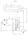
- la fig. 3 est un schéma de raccordement hydraulique.
- Dans l'exemple particulier de réalisation, on utilise trois éléments accumulateurs haute pression 1 précontraints du type Leduc, avec une vessie intérieure tubulaire 2 entourant un tirant central 3 qui va de la bouche de raccordement hydraulique 4 à la queue 5 munie d'un bouchon de gonflage et de contrôle de la pression intérieure d'azote.
- Ces trois accumulateurs 1 ont une grande longueur, d'environ 2 m, et un faible diamètre, et conformément à l'invention, ils sont placés côte à côte à l'intérieur d'une enveloppe unique 6 constituée par une virole 7 en tôle d'acier, de section sensiblement ovale, refermée par deux flasques d'extrémité 8 et 9, par exemple en fonte d'aluminium, qui sont soudés sur la virole 7.
- Pour permettre la mise en place et le démontage des divers accumulateurs 1, les trois accumulateurs sont fixés au moyen de vis 10 sur un couvercle unique 11 se fixant lui-même à l'aide de vis 12 sur le flasque arrière 9, ce couvercle unique 11 constituant en même temps le collecteur de raccordement en parallèle des trois bouches 4 à l'aide de conduits transversaux 13 vers l'embout de raccordement haute pression unique 14.
- A l'autre extrémité, la queue 5 de chaque accumulateur 1 s'introduit de manière étanche dans un embout 15 fixé sur le flasque avant 8 et permettant d'accéder à l'embout de gonflage et de contrôle non représenté.
- Conformément à l'invention, l'espace 16 compris entre l'enveloppe 7 et les trois accumulateurs haute pression 1 constitue l'accumulateur à basse pression communiquant avec l'embout de raccordement à basse pression 17.
- Les divers accumulateurs haute pression 1 étant ainsi rigidement fixés et suspendus par leurs deux extrémités dans l'enveloppe 6, celle-ci constitue un ensemble rigide auto-porteur qui est en outre monté sur trois silent blocks dont deux latéraux 18 proches du flasque arrière 9, et un d'extrémité 19 situé au centre, devant le flasque avant 8.
- L'ensemble compact ainsi constitué, dont la longueur est un peu supérieure à 2 m, la largeur à 0,78 m et la hauteur à 0,43 m, et dont le poids en ordre de marche est d'environ 700 kg, peut être fixé d'un bloc en un emplacement quelconque du véhicule, mais de préférence sur le pavillon 20 du véhicule dans le cas d'un autobus ou d'un fourgon tôlé. La transformation du véhicule se limite donc à la pose des deux canalisations partant des embouts 14 et 17 pour rejoindre les dispositifs hydrostatiques de la transmission récupération.
- A titre d'exemple, comme représenté sur la fig. 3, la canalisation basse pression 17 alimente la pompe de gavage 21 située au niveau inférieur du véhicule, de sorte que la mise en charge de cette canalisation, du fait de la position sur le pavillon 20 du véhicule, est particulièrement favorable. La conduite haute pression 14 est connectée à une boîte à clapets 22 qui assure le raccordement alternatif avec l'une ou l'autre des entrée/sortie 23 et 24 d'une machine hydraulique 25 de récupération-restitution d'énergie raccordée sur la transmission. Ceci dans le cas où la machine 25 est d'un type sans inversion de cylindrée (ou "deux cadrans"). Une telle boîte à clapet 22 peut s'avérer inutile si l'on utilise au contraire pour la machine 25 une machine avec inversion de cylindrée (ou "quatre.cadrans").
- En outre, la machine hydraulique 25 de récupération-restitution elle-même est remplacée par d'autres machines si l'on utilise la disposition décrite par ailleurs dans la demande de brevet français 82 08 855 au nom de la demanderesse.
- Dans tous les cas, et en particulier lors de l'installation sur le pavillon du véhicule, le réservoir basse pression 16 peut être ouvert à l'air libre à l'aide d'un reniflard ou encore être maintenu sous basse pression mais sans nécessiter de membrane de séparation air/huile.
- Naturellement, tout autre type d'accumulateur haute pression 1 que le type Leduc pris comme exemple pourrait être utilisé, par exemple un accumulateur non précontraint à vessie intérieure, la suspension continuant à être assurée à l'arrière par la bouche et du côté avant par tout moyen approprié, éventuellement par une cuvette fixée sur le flasque avant 8 du côté intérieur et dans laquelle vient se centrer le corps du réservoir 1.
- En plus du côté compact, préassemblé et auto-porteur de l'ensemble de réservoirs selon l'invention, celui-ci peut avoir des dimensions et une capacité standard convenant à un grand nombre de types de véhicules, mais il est également possible de prévoir différentes valeurs de capacité en modifiant seulement la longueur de l'enveloppe 7 ainsi que des réservoirs 1, donc sans grande modification des standards et des outillages. Une autre adaptation de la capacité consiste simplement à supprimer certains des accumulateurs 1 pour en modifier le nombre.
Claims (7)
caractérisé par le fait qu'il comporte plusieurs accumulateurs oléopneumatiques (1) cylindriques allongés raccordés hydrauli- quement en parallèle et disposés côte à côte dans une enveloppe unique (6) de faible hauteur, l'espace compris entre ladite enveloppe (6) et lesdits accumulateurs (1) constituant l'accumulateur à basse pression (16).
Applications Claiming Priority (2)
| Application Number | Priority Date | Filing Date | Title |
|---|---|---|---|
| FR8212517 | 1982-07-16 | ||
| FR8212517A FR2530209A1 (fr) | 1982-07-16 | 1982-07-16 | Reservoir d'energie oleopneumatique pour l'accumulation de l'energie de freinage recuperee sur un vehicule |
Publications (3)
| Publication Number | Publication Date |
|---|---|
| EP0099083A2 true EP0099083A2 (fr) | 1984-01-25 |
| EP0099083A3 EP0099083A3 (en) | 1984-02-29 |
| EP0099083B1 EP0099083B1 (fr) | 1987-11-19 |
Family
ID=9276052
Family Applications (1)
| Application Number | Title | Priority Date | Filing Date |
|---|---|---|---|
| EP83106727A Expired EP0099083B1 (fr) | 1982-07-16 | 1983-07-08 | Réservoir d'énergie oléopneumatique pour l'accumulation de l'énergie de freinage récupérée sur un véhicule |
Country Status (5)
| Country | Link |
|---|---|
| US (1) | US4520840A (fr) |
| EP (1) | EP0099083B1 (fr) |
| DE (1) | DE3374538D1 (fr) |
| ES (1) | ES8404259A1 (fr) |
| FR (1) | FR2530209A1 (fr) |
Cited By (1)
| Publication number | Priority date | Publication date | Assignee | Title |
|---|---|---|---|---|
| WO2012148882A1 (fr) * | 2011-04-28 | 2012-11-01 | Robert Bosch Gmbh | Accumulateur hydraulique compact |
Families Citing this family (38)
| Publication number | Priority date | Publication date | Assignee | Title |
|---|---|---|---|---|
| JPH0649447Y2 (ja) * | 1987-03-30 | 1994-12-14 | トヨタ自動車株式会社 | 車両のエアサスペンシヨン用回路 |
| DE4406359A1 (de) * | 1994-02-26 | 1995-09-07 | Kurt Huber | Antriebs-/Brems-/Freilauf-System |
| CN1871439B (zh) | 2003-09-22 | 2011-02-02 | 博施瑞克罗斯公司 | 用于一体化的加压流体系统的压力容器组件 |
| US6922997B1 (en) | 2004-02-03 | 2005-08-02 | International Truck Intellectual Property Company, Llc | Engine based kinetic energy recovery system for vehicles |
| US7363127B2 (en) * | 2004-06-07 | 2008-04-22 | International Truck Intellectual Property Company, Llc | Air brake system monitoring for pre-trip inspection |
| DE202006009223U1 (de) * | 2006-05-17 | 2007-09-27 | Liebherr-Werk Bischofshofen Ges.M.B.H. | Maschine, insbesondere Baumaschine |
| US7802426B2 (en) | 2008-06-09 | 2010-09-28 | Sustainx, Inc. | System and method for rapid isothermal gas expansion and compression for energy storage |
| US8037678B2 (en) | 2009-09-11 | 2011-10-18 | Sustainx, Inc. | Energy storage and generation systems and methods using coupled cylinder assemblies |
| WO2009126784A2 (fr) | 2008-04-09 | 2009-10-15 | Sustainx, Inc. | Systèmes et procédés de stockage et de récupération d’énergie à l’aide de gaz comprimé |
| US8677744B2 (en) | 2008-04-09 | 2014-03-25 | SustaioX, Inc. | Fluid circulation in energy storage and recovery systems |
| US8225606B2 (en) | 2008-04-09 | 2012-07-24 | Sustainx, Inc. | Systems and methods for energy storage and recovery using rapid isothermal gas expansion and compression |
| US20100307156A1 (en) | 2009-06-04 | 2010-12-09 | Bollinger Benjamin R | Systems and Methods for Improving Drivetrain Efficiency for Compressed Gas Energy Storage and Recovery Systems |
| US8359856B2 (en) | 2008-04-09 | 2013-01-29 | Sustainx Inc. | Systems and methods for efficient pumping of high-pressure fluids for energy storage and recovery |
| US7958731B2 (en) | 2009-01-20 | 2011-06-14 | Sustainx, Inc. | Systems and methods for combined thermal and compressed gas energy conversion systems |
| US8474255B2 (en) | 2008-04-09 | 2013-07-02 | Sustainx, Inc. | Forming liquid sprays in compressed-gas energy storage systems for effective heat exchange |
| US8479505B2 (en) | 2008-04-09 | 2013-07-09 | Sustainx, Inc. | Systems and methods for reducing dead volume in compressed-gas energy storage systems |
| US8250863B2 (en) | 2008-04-09 | 2012-08-28 | Sustainx, Inc. | Heat exchange with compressed gas in energy-storage systems |
| US8448433B2 (en) | 2008-04-09 | 2013-05-28 | Sustainx, Inc. | Systems and methods for energy storage and recovery using gas expansion and compression |
| US20110266810A1 (en) | 2009-11-03 | 2011-11-03 | Mcbride Troy O | Systems and methods for compressed-gas energy storage using coupled cylinder assemblies |
| US8240140B2 (en) | 2008-04-09 | 2012-08-14 | Sustainx, Inc. | High-efficiency energy-conversion based on fluid expansion and compression |
| WO2010105155A2 (fr) | 2009-03-12 | 2010-09-16 | Sustainx, Inc. | Systèmes et procédés destinés à améliorer le rendement de transmission pour le stockage d'énergie sous forme de gaz comprimé |
| EP2417361A4 (fr) | 2009-04-06 | 2014-12-10 | Univ Vanderbilt | Accumulateur élastique à haute densité d'énergie et procédé d'utilisation de celui-ci |
| US8104274B2 (en) | 2009-06-04 | 2012-01-31 | Sustainx, Inc. | Increased power in compressed-gas energy storage and recovery |
| MX2012004066A (es) * | 2009-10-05 | 2012-06-08 | Bosch Gmbh Robert | Sistema de almacenamiento de energia que incluye un ensamble de acumulador expansible y deposito. |
| US8171728B2 (en) | 2010-04-08 | 2012-05-08 | Sustainx, Inc. | High-efficiency liquid heat exchange in compressed-gas energy storage systems |
| US8191362B2 (en) | 2010-04-08 | 2012-06-05 | Sustainx, Inc. | Systems and methods for reducing dead volume in compressed-gas energy storage systems |
| US8234863B2 (en) | 2010-05-14 | 2012-08-07 | Sustainx, Inc. | Forming liquid sprays in compressed-gas energy storage systems for effective heat exchange |
| US8495872B2 (en) | 2010-08-20 | 2013-07-30 | Sustainx, Inc. | Energy storage and recovery utilizing low-pressure thermal conditioning for heat exchange with high-pressure gas |
| US8578708B2 (en) | 2010-11-30 | 2013-11-12 | Sustainx, Inc. | Fluid-flow control in energy storage and recovery systems |
| WO2012105933A1 (fr) * | 2011-01-31 | 2012-08-09 | Vanderbilt University | Système accumulateur/réservoir hydraulique élastique |
| US8434524B2 (en) | 2011-01-31 | 2013-05-07 | Vanderbilt University | Elastic hydraulic accumulator/reservoir system |
| WO2012106226A1 (fr) | 2011-02-03 | 2012-08-09 | Vanderbilt University | Systèmes d'accumulateurs multiples et leurs procédés d'utilisation |
| KR20140031319A (ko) | 2011-05-17 | 2014-03-12 | 서스테인쓰, 인크. | 압축 공기 에너지 저장 시스템 내의 효율적인 2상 열전달을 위한 시스템 및 방법 |
| US20130091834A1 (en) | 2011-10-14 | 2013-04-18 | Sustainx, Inc. | Dead-volume management in compressed-gas energy storage and recovery systems |
| US9249847B2 (en) | 2011-12-16 | 2016-02-02 | Vanderbilt University | Distributed piston elastomeric accumulator |
| FR3000704B1 (fr) * | 2013-01-07 | 2015-02-13 | Technoboost | Module hydraulique comportant des accumulateurs haute et basse pression, pour un vehicule hybride |
| US9127811B2 (en) | 2013-06-05 | 2015-09-08 | Louis P. Vickio, Jr. | Hydraulic accumulator |
| EP3267046A1 (fr) | 2016-07-07 | 2018-01-10 | DANA ITALIA S.r.l. | Système de récupération d'énergie à partir d'un actionneur hydraulique |
Citations (4)
| Publication number | Priority date | Publication date | Assignee | Title |
|---|---|---|---|---|
| US1891644A (en) * | 1931-02-12 | 1932-12-20 | Westinghouse Air Brake Co | Reservcir construction |
| FR2188574A5 (fr) * | 1972-06-06 | 1974-01-18 | Westinghouse Freins & Signaux | |
| FR2323067A1 (fr) * | 1975-09-08 | 1977-04-01 | Carman Vincent | Circuit hydraulique de freinage et d'acceleration pour vehicule |
| FR2425609A1 (fr) * | 1978-05-12 | 1979-12-07 | Cytec France | Dispositif de stockage d'energie dans une enceinte a plusieurs enveloppes elastiques. |
Family Cites Families (10)
| Publication number | Priority date | Publication date | Assignee | Title |
|---|---|---|---|---|
| US339885A (en) * | 1886-04-13 | Mode of re-enforcing tubular or hollow structures | ||
| US194217A (en) * | 1877-08-14 | Improvement in reservoirs for compressed air | ||
| US846266A (en) * | 1905-11-22 | 1907-03-05 | Bethlehem Steel Corp | Multiple-pressure system. |
| US1692670A (en) * | 1924-12-30 | 1928-11-20 | Mesurier Louis John Le | Apparatus for storing fluid under pressure |
| US2331921A (en) * | 1938-05-31 | 1943-10-19 | Mercier Jean | Storage device |
| US4062356A (en) * | 1974-12-04 | 1977-12-13 | U.S. Divers Co. | Underwater diving system |
| IL46964A (en) * | 1975-03-30 | 1977-06-30 | Technion Res & Dev Foundation | Hydrostatic relay system |
| DE2515048C3 (de) * | 1975-04-07 | 1982-02-18 | M.A.N. Maschinenfabrik Augsburg-Nuernberg Ag, 8000 Muenchen | Antriebsanordnung mit Energiespeicher, insbesondere für Straßenfahrzeuge |
| DE3031232A1 (de) * | 1980-08-19 | 1982-03-25 | Dipl.-Phys. Dr. Hugo 4750 Unna Balster | Verfahren und vorrichtung zum uebertragen und/oder speichern von rotationsenergie |
| US4441573A (en) * | 1980-09-04 | 1984-04-10 | Advanced Energy Systems Inc. | Fuel-efficient energy storage automotive drive system |
-
1982
- 1982-07-16 FR FR8212517A patent/FR2530209A1/fr active Granted
-
1983
- 1983-07-08 DE DE8383106727T patent/DE3374538D1/de not_active Expired
- 1983-07-08 EP EP83106727A patent/EP0099083B1/fr not_active Expired
- 1983-07-12 US US06/513,138 patent/US4520840A/en not_active Expired - Lifetime
- 1983-07-15 ES ES524140A patent/ES8404259A1/es not_active Expired
Patent Citations (4)
| Publication number | Priority date | Publication date | Assignee | Title |
|---|---|---|---|---|
| US1891644A (en) * | 1931-02-12 | 1932-12-20 | Westinghouse Air Brake Co | Reservcir construction |
| FR2188574A5 (fr) * | 1972-06-06 | 1974-01-18 | Westinghouse Freins & Signaux | |
| FR2323067A1 (fr) * | 1975-09-08 | 1977-04-01 | Carman Vincent | Circuit hydraulique de freinage et d'acceleration pour vehicule |
| FR2425609A1 (fr) * | 1978-05-12 | 1979-12-07 | Cytec France | Dispositif de stockage d'energie dans une enceinte a plusieurs enveloppes elastiques. |
Cited By (1)
| Publication number | Priority date | Publication date | Assignee | Title |
|---|---|---|---|---|
| WO2012148882A1 (fr) * | 2011-04-28 | 2012-11-01 | Robert Bosch Gmbh | Accumulateur hydraulique compact |
Also Published As
| Publication number | Publication date |
|---|---|
| US4520840A (en) | 1985-06-04 |
| EP0099083A3 (en) | 1984-02-29 |
| EP0099083B1 (fr) | 1987-11-19 |
| DE3374538D1 (en) | 1987-12-23 |
| ES524140A0 (es) | 1984-04-16 |
| FR2530209A1 (fr) | 1984-01-20 |
| FR2530209B1 (fr) | 1985-01-11 |
| ES8404259A1 (es) | 1984-04-16 |
Similar Documents
| Publication | Publication Date | Title |
|---|---|---|
| EP0099083A2 (fr) | Réservoir d'énergie oléopneumatique pour l'accumulation de l'énergie de freinage récupérée sur un véhicule | |
| FR2791621A1 (fr) | Dispositif de rangement de casque pour motocyclette | |
| FR2839524A1 (fr) | Vehicule utilitaire comprenant une base pivotant sur un dispositif de deplacement, et une fleche a l'interieur de laquelle s'etendent des conduites hydrauliques, notamment pelle retrocaveuse | |
| FR2878936A1 (fr) | Procede d'isolation thermique de conduites coaxiales par un materiau isolant particulaire | |
| EP3259404B1 (fr) | Structure de support et d'ancrage d'éolienne maritime du type embase gravitaire et procédé de remorquage et dépose en mer | |
| FR2865709A1 (fr) | Systeme de montage pour des vehicules utilitaires | |
| OA11623A (fr) | Conduite de circulation de fluide sous pression etprocédé de réalisation d'une telle conduite. | |
| FR2749647A1 (fr) | Condenseur a reservoir separe pour installation de climatisation, notamment de vehicule automobile | |
| EP0895017A1 (fr) | Réservoir pour fluide sous pression | |
| EP3650319B1 (fr) | Structure de carrosserie permettant le passage de fluide ou de gaz sous pression et caisse associée | |
| EP3463978B1 (fr) | Véhicule hydrocureur comprenant des réservoirs d'eau en matière plastique et une citerne de stockage montée basculante de façon dissociée des réservoirs | |
| EP0114010A2 (fr) | Réservoir pour stocker les carburants d'alimentation d'un moteur à combustion interne utilisant du carburant liquide et du carburant gazeux, notamment liquéfié | |
| EP1401691A1 (fr) | Reservoir hydraulique et dispositif de freinage comportant un tel reservoir | |
| EP0862521A1 (fr) | Reservoirs toriques de securite pour gaz de petrole liquifie pour vehicules a bicarburation | |
| FR2616464A1 (fr) | Caisson pour constructions hydrotechniques | |
| EP1135647B1 (fr) | Reservoir destine a contenir des fluides sous pression comportant des renforts internes | |
| FR2783034A1 (fr) | Reservoir destine a contenir du fluide sous pression comportant des renforts internes | |
| WO2016132056A1 (fr) | Structure de support et d'ancrage d'eolienne maritime du type tour treillis et procede de remorquage et depose en mer | |
| EP3984816B1 (fr) | Cuve pour camion hydrocureur | |
| FR2482029A1 (fr) | Soupape a relais de protection contre les surcharges pour freins de service et a ressort accumule combines pour vehicules, en particulier vehicules routiers | |
| WO2020217038A1 (fr) | Réservoir modulaire pour stocker un liquide et procédé d'assemblage d'un tel réservoir | |
| FR2836705A1 (fr) | Verin comprenant une admission de fluide unique pour les largages d'une charge | |
| FR3031326A1 (fr) | Essieu arriere de vehicule automobile muni d'un reservoir integre de reducteur pour systeme de reduction selective catalytique | |
| CN115042693A (zh) | 一种皮卡防滚架和皮卡车 | |
| FR2738282A1 (fr) | Machine a creuser a bouclier |
Legal Events
| Date | Code | Title | Description |
|---|---|---|---|
| PUAI | Public reference made under article 153(3) epc to a published international application that has entered the european phase |
Free format text: ORIGINAL CODE: 0009012 |
|
| PUAL | Search report despatched |
Free format text: ORIGINAL CODE: 0009013 |
|
| AK | Designated contracting states |
Designated state(s): BE DE GB IT SE |
|
| AK | Designated contracting states |
Designated state(s): BE DE GB IT SE |
|
| 17P | Request for examination filed |
Effective date: 19840425 |
|
| ITF | It: translation for a ep patent filed |
Owner name: BARZANO' E ZANARDO MILANO S.P.A. |
|
| GRAA | (expected) grant |
Free format text: ORIGINAL CODE: 0009210 |
|
| AK | Designated contracting states |
Kind code of ref document: B1 Designated state(s): BE DE GB IT SE |
|
| REF | Corresponds to: |
Ref document number: 3374538 Country of ref document: DE Date of ref document: 19871223 |
|
| GBT | Gb: translation of ep patent filed (gb section 77(6)(a)/1977) | ||
| PLBE | No opposition filed within time limit |
Free format text: ORIGINAL CODE: 0009261 |
|
| STAA | Information on the status of an ep patent application or granted ep patent |
Free format text: STATUS: NO OPPOSITION FILED WITHIN TIME LIMIT |
|
| 26N | No opposition filed | ||
| ITTA | It: last paid annual fee | ||
| EAL | Se: european patent in force in sweden |
Ref document number: 83106727.7 |
|
| PGFP | Annual fee paid to national office [announced via postgrant information from national office to epo] |
Ref country code: GB Payment date: 20010614 Year of fee payment: 19 |
|
| PGFP | Annual fee paid to national office [announced via postgrant information from national office to epo] |
Ref country code: SE Payment date: 20010702 Year of fee payment: 19 |
|
| PGFP | Annual fee paid to national office [announced via postgrant information from national office to epo] |
Ref country code: DE Payment date: 20010713 Year of fee payment: 19 Ref country code: BE Payment date: 20010713 Year of fee payment: 19 |
|
| REG | Reference to a national code |
Ref country code: GB Ref legal event code: IF02 |
|
| PG25 | Lapsed in a contracting state [announced via postgrant information from national office to epo] |
Ref country code: GB Free format text: LAPSE BECAUSE OF NON-PAYMENT OF DUE FEES Effective date: 20020708 |
|
| PG25 | Lapsed in a contracting state [announced via postgrant information from national office to epo] |
Ref country code: SE Free format text: LAPSE BECAUSE OF NON-PAYMENT OF DUE FEES Effective date: 20020709 |
|
| PG25 | Lapsed in a contracting state [announced via postgrant information from national office to epo] |
Ref country code: BE Free format text: LAPSE BECAUSE OF NON-PAYMENT OF DUE FEES Effective date: 20020731 |
|
| BERE | Be: lapsed |
Owner name: *RENAULT VEHICULES INDUSTRIELS Effective date: 20020731 |
|
| PG25 | Lapsed in a contracting state [announced via postgrant information from national office to epo] |
Ref country code: DE Free format text: LAPSE BECAUSE OF NON-PAYMENT OF DUE FEES Effective date: 20030201 |
|
| GBPC | Gb: european patent ceased through non-payment of renewal fee |
Effective date: 20020708 |
|
| EUG | Se: european patent has lapsed |