EP0098768B1 - Sonde pour magnétomètre - Google Patents
Sonde pour magnétomètre Download PDFInfo
- Publication number
- EP0098768B1 EP0098768B1 EP19830401287 EP83401287A EP0098768B1 EP 0098768 B1 EP0098768 B1 EP 0098768B1 EP 19830401287 EP19830401287 EP 19830401287 EP 83401287 A EP83401287 A EP 83401287A EP 0098768 B1 EP0098768 B1 EP 0098768B1
- Authority
- EP
- European Patent Office
- Prior art keywords
- magnetic
- winding
- probe
- alternating current
- intended
- Prior art date
- Legal status (The legal status is an assumption and is not a legal conclusion. Google has not performed a legal analysis and makes no representation as to the accuracy of the status listed.)
- Expired
Links
- 239000000523 sample Substances 0.000 title claims description 7
- 230000005291 magnetic effect Effects 0.000 claims description 24
- 238000004804 winding Methods 0.000 claims description 17
- 230000005284 excitation Effects 0.000 claims description 12
- 238000005259 measurement Methods 0.000 claims description 9
- 239000004020 conductor Substances 0.000 claims description 3
- 230000002093 peripheral effect Effects 0.000 claims description 3
- 239000003302 ferromagnetic material Substances 0.000 claims description 2
- 239000000463 material Substances 0.000 description 4
- 238000010586 diagram Methods 0.000 description 2
- 230000004907 flux Effects 0.000 description 2
- 239000000696 magnetic material Substances 0.000 description 2
- 230000035699 permeability Effects 0.000 description 2
- RYGMFSIKBFXOCR-UHFFFAOYSA-N Copper Chemical compound [Cu] RYGMFSIKBFXOCR-UHFFFAOYSA-N 0.000 description 1
- 229910052802 copper Inorganic materials 0.000 description 1
- 239000010949 copper Substances 0.000 description 1
- 230000008878 coupling Effects 0.000 description 1
- 238000010168 coupling process Methods 0.000 description 1
- 238000005859 coupling reaction Methods 0.000 description 1
- 238000001514 detection method Methods 0.000 description 1
- 230000000694 effects Effects 0.000 description 1
- 238000005516 engineering process Methods 0.000 description 1
- 238000004519 manufacturing process Methods 0.000 description 1
- 239000010453 quartz Substances 0.000 description 1
- 230000035945 sensitivity Effects 0.000 description 1
- VYPSYNLAJGMNEJ-UHFFFAOYSA-N silicon dioxide Inorganic materials O=[Si]=O VYPSYNLAJGMNEJ-UHFFFAOYSA-N 0.000 description 1
- 238000003466 welding Methods 0.000 description 1
Images

Classifications
-
- G—PHYSICS
- G01—MEASURING; TESTING
- G01R—MEASURING ELECTRIC VARIABLES; MEASURING MAGNETIC VARIABLES
- G01R33/00—Arrangements or instruments for measuring magnetic variables
- G01R33/02—Measuring direction or magnitude of magnetic fields or magnetic flux
- G01R33/04—Measuring direction or magnitude of magnetic fields or magnetic flux using the flux-gate principle
Definitions
- the subject of the invention is a probe of a magnetic field measuring device or magnetometer, and more particularly for magnetometers in which an alternating current creates in a magnetic circuit a flux reaching saturation values, to which the resulting flux is superimposed. of the field to be measured, the voltage collected in a winding arranged around the circuit allowing the measurement of this field.
- the magnetometers according to the prior art comprise saturable magnetic cores for which there is practically no coupling between the excitation winding and the measurement winding.
- the value of the field to be measured is obtained by the asymmetry of the signals collected during two successive half-waves. It is known to measure this asymmetry or the harmonic level 2 directly.
- the invention proposes to combine the magnetic winding and the excitation winding by manufacturing them using a single wire consisting of a central part made of conductive material and a peripheral part. made of ferromagnetic material.
- Fig. 1 shows the general diagram of a probe for a magnetometer with a saturable core called flux-gate in Anglo-American literature.
- the principle of measurement of a magnetic field H generally consists in detecting even harmonics, in particular harmonic 2, which arises from the saturation of a magnetic core under the effect of the field to be measured which is superimposed on the field d alternative excitement.
- the core In order to minimize the excitation power, by removing the demagnetizing field, the core is of cylindrical shape and the excitation winding is wound in a toroidal fashion along the core producing an excitation field h E whose lines of force surround the core as shown in fig. 1.
- the core forms a tube 1 made of a material with high permeability, the excitation winding 2 producing an alternating field h E.
- the measurement signal is obtained.
- the excitation field h E is produced by passing the current directly through the core 1.
- Fig. 2 shows a magnetic core produced with interlaced ribbons 21 according to the prior art.
- the dimension of the section of the ribbon is of the order of a few millimeters in width and a few hundredths of a millimeter in thickness.
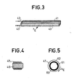
- Figs. 3, 4 and 5 represent an alternative embodiment of the magnetic core according to the invention.
- a quartz support 30 for example, in the form of an elongated rectangular parallelepiped, is wound in contiguous turns, with an insulated wire, a wire of round section 41 in several layers, the two ends 42 and 43 of which are left free on one side of the support
- the wire 41 is composed of a central part 60 of conductive material such as copper and of a peripheral part 61 of magnetic material such as Mumetal or an equivalent magnetic amorphous material, this material being covered with an insulating layer. 62.
- the excitation current is sent into the fif by the two ends 42 and 43 producing the excitation field h E.
- the probe thus obtained according to this embodiment is of small dimensions allowing the punctual measurement of a magnetic field.
Landscapes
- Physics & Mathematics (AREA)
- Condensed Matter Physics & Semiconductors (AREA)
- General Physics & Mathematics (AREA)
- Measuring Magnetic Variables (AREA)
Applications Claiming Priority (2)
| Application Number | Priority Date | Filing Date | Title |
|---|---|---|---|
| FR8211658A FR2529683A1 (fr) | 1982-07-02 | 1982-07-02 | Sonde pour magnetometre |
| FR8211658 | 1982-07-02 |
Publications (2)
| Publication Number | Publication Date |
|---|---|
| EP0098768A1 EP0098768A1 (fr) | 1984-01-18 |
| EP0098768B1 true EP0098768B1 (fr) | 1986-01-29 |
Family
ID=9275637
Family Applications (1)
| Application Number | Title | Priority Date | Filing Date |
|---|---|---|---|
| EP19830401287 Expired EP0098768B1 (fr) | 1982-07-02 | 1983-06-21 | Sonde pour magnétomètre |
Country Status (2)
| Country | Link |
|---|---|
| EP (1) | EP0098768B1 (OSRAM) |
| FR (1) | FR2529683A1 (OSRAM) |
Cited By (1)
| Publication number | Priority date | Publication date | Assignee | Title |
|---|---|---|---|---|
| DE4027020A1 (de) * | 1990-08-27 | 1992-03-05 | Heinrich Liebig Gmbh | Verfahren und vorrichtung zur feststellung des vorhandenseins von metallischen bewehrungselementen in der umgebung von bohrloechern in beton-bauteilen |
Families Citing this family (3)
| Publication number | Priority date | Publication date | Assignee | Title |
|---|---|---|---|---|
| FR2547927B1 (fr) * | 1983-06-24 | 1986-01-17 | Thomson Csf | Sonde a noyau saturable, notamment pour magnetometre |
| US5239290A (en) * | 1992-03-25 | 1993-08-24 | Schonstedt Instrument Company | Magnetic cores for saturable core measuring devices and methods of manufacturing such cores |
| FR2928006B1 (fr) * | 2008-02-26 | 2011-03-04 | Univ Claude Bernard Lyon | Procede de fabrication d'un capteur de champ magnetique et capteur de champ magnetique obtenu |
Family Cites Families (4)
| Publication number | Priority date | Publication date | Assignee | Title |
|---|---|---|---|---|
| US2916696A (en) * | 1955-12-05 | 1959-12-08 | Erick O Schonstedt | Saturable measuring device and magnetic core therefor |
| US2981885A (en) * | 1958-07-21 | 1961-04-25 | Erick O Schonstedt | Saturable measuring device and magnetic core therefor |
| US3434047A (en) * | 1966-07-25 | 1969-03-18 | Precision Winding Co Inc | Magnetic field sensing and measuring apparatus |
| JPS5134308Y2 (OSRAM) * | 1971-04-30 | 1976-08-24 |
-
1982
- 1982-07-02 FR FR8211658A patent/FR2529683A1/fr active Granted
-
1983
- 1983-06-21 EP EP19830401287 patent/EP0098768B1/fr not_active Expired
Cited By (1)
| Publication number | Priority date | Publication date | Assignee | Title |
|---|---|---|---|---|
| DE4027020A1 (de) * | 1990-08-27 | 1992-03-05 | Heinrich Liebig Gmbh | Verfahren und vorrichtung zur feststellung des vorhandenseins von metallischen bewehrungselementen in der umgebung von bohrloechern in beton-bauteilen |
Also Published As
| Publication number | Publication date |
|---|---|
| EP0098768A1 (fr) | 1984-01-18 |
| FR2529683B1 (OSRAM) | 1985-02-08 |
| FR2529683A1 (fr) | 1984-01-06 |
Similar Documents
| Publication | Publication Date | Title |
|---|---|---|
| US6380735B1 (en) | Orthogonal flux-gate type magnetic sensor | |
| JP4835805B2 (ja) | マグネトインピーダンスセンサ素子及びその製造方法 | |
| US7145331B2 (en) | Magnetic sensor having a closed magnetic path formed by soft magnetic films | |
| JP3693119B2 (ja) | 電磁コイル付マグネト・インピーダンス・センサ素子 | |
| JP4655162B2 (ja) | マグネトインピーダンス素子およびマグネトインピーダンスセンサ | |
| EP0286079A2 (en) | Sensing devices utilizing magneto electric transducers | |
| US4362990A (en) | Current- and voltage-measurement transducer | |
| JP3341237B2 (ja) | 磁気センサ素子 | |
| US3829894A (en) | Parametric magnetic sensor | |
| EP0098768B1 (fr) | Sonde pour magnétomètre | |
| JP4047955B2 (ja) | 磁気インピーダンスセンサ | |
| JPH05297083A (ja) | 磁界感応装置 | |
| FR2817622A1 (fr) | Micromagnetometre a porte de flux | |
| JP3360168B2 (ja) | 磁気インピーダンス素子 | |
| EP0781448B1 (fr) | Tete magnetique planaire a magnetoresistance multicouche longitudinale | |
| JP2009036717A (ja) | 磁気センサ | |
| JPH09318720A (ja) | フラックスゲート磁気センサ | |
| JP3676579B2 (ja) | 磁気インピーダンス素子 | |
| JP3634281B2 (ja) | 磁気インピーダンス効果センサー | |
| JP3052050B2 (ja) | 蛇行コイル型電磁超音波トランスデューサ | |
| RU2059259C1 (ru) | Магниточувствительный элемент | |
| JP2005227297A (ja) | 電磁コイル付マグネト・インピーダンス・センサ素子 | |
| US3426269A (en) | Magnetic field sensor including means to minimize permanent magnetization | |
| EP0132422A1 (fr) | Sonde à noyau saturable notamment pour magnétomètre | |
| EP0254613A1 (fr) | Noyau pour compas magnétique |
Legal Events
| Date | Code | Title | Description |
|---|---|---|---|
| PUAI | Public reference made under article 153(3) epc to a published international application that has entered the european phase |
Free format text: ORIGINAL CODE: 0009012 |
|
| AK | Designated contracting states |
Designated state(s): DE GB IT SE |
|
| 17P | Request for examination filed |
Effective date: 19840208 |
|
| RBV | Designated contracting states (corrected) |
Designated state(s): IT SE |
|
| GRAA | (expected) grant |
Free format text: ORIGINAL CODE: 0009210 |
|
| AK | Designated contracting states |
Designated state(s): IT SE |
|
| ITF | It: translation for a ep patent filed | ||
| PLBE | No opposition filed within time limit |
Free format text: ORIGINAL CODE: 0009261 |
|
| STAA | Information on the status of an ep patent application or granted ep patent |
Free format text: STATUS: NO OPPOSITION FILED WITHIN TIME LIMIT |
|
| 26N | No opposition filed | ||
| PG25 | Lapsed in a contracting state [announced via postgrant information from national office to epo] |
Ref country code: SE Effective date: 19890622 |
|
| EUG | Se: european patent has lapsed |
Ref document number: 83401287.4 Effective date: 19900418 |
|
| PGFP | Annual fee paid to national office [announced via postgrant information from national office to epo] |
Ref country code: FR Payment date: 19950131 Year of fee payment: 11 |