EP0098086A2 - Elément de cheminée préfabriqué - Google Patents
Elément de cheminée préfabriqué Download PDFInfo
- Publication number
- EP0098086A2 EP0098086A2 EP83303552A EP83303552A EP0098086A2 EP 0098086 A2 EP0098086 A2 EP 0098086A2 EP 83303552 A EP83303552 A EP 83303552A EP 83303552 A EP83303552 A EP 83303552A EP 0098086 A2 EP0098086 A2 EP 0098086A2
- Authority
- EP
- European Patent Office
- Prior art keywords
- unit
- flue
- housing
- liner
- spigot
- Prior art date
- Legal status (The legal status is an assumption and is not a legal conclusion. Google has not performed a legal analysis and makes no representation as to the accuracy of the status listed.)
- Granted
Links
Images


Classifications
-
- E—FIXED CONSTRUCTIONS
- E04—BUILDING
- E04F—FINISHING WORK ON BUILDINGS, e.g. STAIRS, FLOORS
- E04F17/00—Vertical ducts; Channels, e.g. for drainage
- E04F17/02—Vertical ducts; Channels, e.g. for drainage for carrying away waste gases, e.g. flue gases; Building elements specially designed therefor, e.g. shaped bricks or sets thereof
Definitions
- One known unit of this type is of precast concrete material.
- Each unit is essentially a monolithic block having a through hole defining the flue.
- a plurality of cut-out channels extend axially from the bottom of the block to a position adjacent the top. The channels are closed off at the top end to provide a seat over which is laid a layer of mortar onto which is laid the next block with its closed end uppermost.
- the major disadvantage of such units is that as manufactured they do not satisfy the requirements of the appropriate building regulations and standards.
- the material generally used is water permeable the outer faces must be rendered or a brick cladding provided around the assembled chimney. Further, a separate rendering or lining of the flue on site is also required to make it acid resistant.
- the units because of their weight are relatively difficult to handle. Further, the operation of building a chimney using these units is time consuming particularly due to the requirement of a mortar layer between each unit, the necessary cladding or rendering and in some cases the necessity for inserting a flue liner in each unit.
- One object of this invention is to provide a prefabricated flue unit which will overcome these disadvantages and in particular will satisfy current building regulation requirements and comply with appropriate standards.
- a prefabricated flue unit according to the invention is characterised in that the unit is a composite unit, the casing comprising an outer housing of a fibre reinforced cementitious material and the unit includes an inner liner of an acid and fire resistant material for the flue and an insulating fire resistant infill material interposed between the liner and housing.
- One particular advantage of the invention is it provides a relatively lightweight prefabricated unit from which a chimney which as manufactured will satisfy current building regulations and standards and can be quickly and easily constructed.
- the casing of fibre reinforced cementitious material not only gives a very lightweight unit but also because the material is dense the outer surfaces have low water permeability and generally do not require rendering or cladding. This, it will be appreciated considerably reduces the construction time over presently known units.
- the housing has a high load bearing structural strength and may be provided with decorative work on the outer faces.
- the flue unit includes a spacing member having a cut-out portion for reception of the liner to retain it in position in the housing.
- the advantage of this feature of the invention is that particularly during manufacture of the unit, the liner is retained in a desired usually centrally located position in the housing.
- the spacing member is integrally moulded with the housing.
- spacing member is of the same material as that of the housing it may be cast in during manufacture and greatly assists in positively locating the liner in its desired position.
- the unit includes an integral interlocking means for engaging one unit with another flue unit.
- the advantage of this feature is that it facilitates the assembly of the units on site without the requirement of a layer of mortar between the units.
- the housing may be substantially rectangular in cross-section having side walls, and the spacing member extends between the side walls, one end of the housing being recessed to define a socket part and the other end defining a spigot part for interlocking with a complementary socket part of another unit, the spigot and socket parts forming the interlocking means.
- the advantage of the spigot and socket arrangement is that it assists in positively locating and interlocking one flue unit with another.
- the spacing member includes a tapered step portion defining together with the side walls the spigot part.
- the advantage of this feature of the invention is that the step portion not only assists in the positive location of the spigot part in the socket part but also forms a water shed at the joint between adjacent units.
- the spacing member is spaced-apart from one end of the housing to define together with the side walls at that end a socket part and the side walls adjacent the other end are formed with a tapered step portion to define the spigot part for interlocking with a socket part of an adjacent unit.
- the advantage of this arrangement is that due to the positioning of the spacing member the positive location and interlocking of the units on site is assured.
- the tapered step portion again provides a water shed at the joint.
- the liner is formed with a male part at one end for engagement with a complementary female part at the other end of a liner of an adjacent unit.
- the infill material is shaped to form a male or female part for interlocking with a complementary male or female part integral with the housing.
- housing and liner have the same vertical axis of symmetry.
- the thickness of the housing is between 4 and 15 mm, preferably between 5 and 8 mm.
- the thickness of the housing is small, it is relatively lightweight.
- the infill material is formed with a plurality of longitudinally extending voids to allow passage of air and condensates.
- the advantage of this feature is that it provides a passageway through which air and condensate may pass through an assembled chimney.
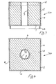
- a prefabricated flue unit indicated generally by the reference numeral 1.
- the unit 1 comprises an outer housing 2, an inner liner 3 spaced-apart from the housing 2 to define therebetween a cavity which is filled with a lightweight fire- resistant insulating infill material 4.
- the unit 1 is prefabricated as a single lightweight composite unit a number of the units being interlocked one with another on site to build up a chimney or flue.
- the housing 2 in this case is of rectangular box-shape having an open top 5, four depending side walls 6 and a base 7 communicating with the side walls 6 through a tapered step portion 8.
- Typical dimensions for the housing are 240 mm wide, 240 mm deep and 280 mm high.
- the housing 2 is moulded from a fibre-reinforced cementitious material, in this case, glass fibre reinforced cement (G.R.C.) to a wall thickness of between 4 and 15 mm and in most cases between 5 and 8 mm.
- G.R.C. glass fibre reinforced cement
- the G.R.C. is sufficiently dense at these narrow thicknesses to provide the necessary load bearing strength and is substantially impervious to water so that rendering or cladding of a chimney constructed of a number of these units 1 is not required.
- the unit is relatively lightweight and can be easily handled by a single workman. It will further be appreciated that if desired, the housing could be formed with decorative work to give an aesthetically pleasing outer appearance to an assembled chimney or flue.
- the base 7 of the housing 2 includes a central circular cut-out portion 9 for reception of the cylindrical liner 3. Essentially the base 7 provides a spacing member for retaining the liner 3 in position in the housing 2.
- the liner 3 is of any suitable fire and acid resistant material such as clay or metal such as stainless steel. It will be noted that the liner 3 and housing 2 in this case have the same vertical axis of symmetry.
- the infill material 4 may be of any loose, granular, fibrous or a bound cohesive composite material with a density of between 350 kg per m 3 and 500 kg per m 3 . It may be, for example, a cementitious mixture of portland cement, expanded polystyrene beads and an insulating aggregate material such as perlite or vermiculite.
- Both the top of the liner 3 and the insulating infill material 4 stop short of the open top 5 of the housing 2 to define a socket 15 having a depth h for reception of a complementary spigot 14 formed by the step portion 8 and base 7 of another flue unit 1.
- the step portion 8 extends for a distance d l which is equal to the depth h of the socket 15 so that when a spigot in one flue unit 1 is inserted in a complementary socket 15 in another the exposed rim of the liner 3 in one flue unit 1 will fit substantially flush with the exposed rim of the liner 2 in an adjacent flue unit 1 to form a substantially gas-tight joint.
- step portions 8 act as lead-in guides for insertion of the spigot of one flue unit in the socket 15 of another unit so that on assembly the side walls 5 of adjacent units 1 are also substantially flush.
- the spigot and socket essentially form an interlocking means for engaging one flue unit with another.
- a chimney flue 16 constructed from a plurality of the prefabricated composite units 1 just described.
- the flue 16 is built up from a bottom support plinth 17-which is constructed with a complementary socket for reception of the base or spigot end 14 of one of the units 1.
- the next unit is then laid on top of the lowermost unit with its socket end 15 uppermost and the spigot end 14 engaging in the socket of the lower unit. Because of the tight fit of the spigot 14 in the socket 15 no mortar is required at the joint between adjacent units.
- the flue 16 is built up in this way by placing a number of units 1 one on top of another. Typically the units are built up to make a domestic chimney or flue to a height of between 8 and 12 metres.
- step portion 8 on each spigot end 14 acts as a barrier or shed to prevent ingress of moisture through the joint between adjacent units.
- FIG. 5 there is illustrated another flue 20 constructed from a plurality of the units 1 described above with reference to Figs. 1 to 3.
- the units are turned so that their spigot ends 14 are uppermost.
- the socket 15 of one unit is inserted in the spigot 14 of an adjacent unit to build up the flue 20.
- the particular advantage of this construction is that the step portion 8 forms a particularly effective moisture or water barrier to prevent ingress through the joint between adjacent units.
- Fig. 6 there is illustrated another construction of prefabricated flue unit according to the invention indicated generally by the reference numeral 30.
- the unit 30 is similar to that described above with reference to Figs. 1 to 3 and like parts are assigned the same reference numerals.
- three segment-shaped elongate longitu.dinal passageways 31 extend through the insulating material 4.
- Each passageway 31 is of arcuate shape in horizontal cross-section and is situated adjacent the outer periphery of the liner 3.
- the base 7 of the housing 2 is provided with slots (not shown) corresponding in shape to the passageways 31 to allow a continuous passageway to be built up through an assembled chimney or flue through which air and condensate may pass.
- passageways may be provided through the insulating material to allow passage of air and condensation.
- the passageways it is not essential for the passageways to be provided around the periphery of the liner, they could, for example, be provided through the main body of the insulating material intermediate the liner and housing.
- Fig. 7 there is illustrated an alternative prefabricated flue unit indicated generally by the reference numeral 40.
- the unit 40 is similar to that described above with reference to Figs. 1 to 3 and like parts are assigned the same reference numerals.
- the spacing member or base 7 of the housing 2 is spaced-apart from the bottom end of the housing to define together with the side walls 6 at that end a socket part 41.
- the side walls 6 adjacent the other end are formed with a straight step portion 42 to define a spigot part 43 for interlocking with a socket part 41 of an adjacent unit as may be seen particularly in Fig. 8.
- the liner 3 extends to a position flush with the free ends of the walls of the housing at both ends and the infill material 4 is filled up to the uppermost edge of the housing walls 6.
- the liner 3 is cut-away adjacent its top and bottom ends to form a female socket part 44 at the spigot end 43 of the housing and an oppositely directed complementary shaped male spigot part 45 at the socket end 41 of the housing 2.
- each flue unit 40 On assembly, and referring particularly to Fig. 8 each flue unit 40 is positioned with its spigot end 43 uppermost, the socket end 41 of an adjacent unit being inserted over the spigot end 43 and the male and female parts 43, 44 of adjacent flue liners 3 interengaging to form a gas-tight joint.
- Fig. 9 there is illustrated an alternative construction of flue unit 60 similar to that described above with reference to Fig. 8 and like parts are assigned the same reference numerals.
- the means for interlocking one flue unit with another comprises a female socket part formed from a channel-shaped groove 61 extending around the periphery of the infill material 4 adjacent the top free end of the housing side wall 6 and a complementary shaped spigot wall 62 integral with and depending downwardly from the base 7 of the housing 2.
- FIGs. 10 and 11 there is illustrated another construction of composite flue unit 70 similar to that described above with reference to Figs. 1 to 3, like parts being assigned the same reference numerals.
- the uppermost end of the unit 70 is closed off by a top spacing plate 71 having a central circular cut-out portion 72 for the liner 3.
- Four triangular projections 73 are formed integral with and upstand from the plates 71 adjacent the corners thereof to form male spigot parts for interengagement in complementary shaped recesses 74 in the base member 7 of an adjacent unit 70.
- the base 7 is cut-away leaving four angled strips 75 defining together with the side walls 6 of the housing 2 the recesses 74.
- the infill material 4 is extended to lie flush with the outer face of each strip 75 between the recesses 74.
- interlocking means The advantage of this particular construction of interlocking means is that the units are easily located one with another in use and form a particularly good joint which again does not require mortar.
- the mixture used for the outer housing is preferably made by a high shear mixing process using a method and apparatus such as described in U.K. Patent Specification No. 1,553,196.
- This process and apparatus is particularly suitable for making casings from a fibre reinforced cementitious material such as G.R.C. and gives a high density product with narrow wall thickness that has relatively high structural strength.
- a typical density for the material is 2.2 tons/m 3 with a water vapour pressure of less than 1.3 metric perms. when measured according to BS3177 (1959).
- the material with this specification also passes the ISO impermeability test. It will be appreciated that the liner may also be formed of this material.
- the housing and liner are initially joined together and the insulating material filled into the cavity formed therebetween however, in some cases the inner liner is fitted as a separate unit after the insulation material has been cast or formed in the housing.
- the housing may be moulded from one or any number of parts cemented together and a mandrel inserted through the housing to form a void for reception of the liner while the cementitious infill material is poured in.
- the plate may be removable and may be used only during the fabrication procedure.
- the plate may be formed integral with the liner.
- the spacing member may be formed by a plurality of such plate members or cut away to any desired shape. It will be appreciated that in the case where the plate is reduced to provide only a locating lip the filler also locates the liner.
- the liner and housing may be cemented together and the particular case where the infill material is cementitious based the infill itself may provide the necessary binding.
- the housing liners or infill material may be a force or press fit one with another or may comprise any suitable shape and configuration of complementary interengagable or interlocking formations.
- the spigot and socket arrangements illustrated for the housing may equally be applied to the liners and infill material and vice versa.
- the spigot or socket may be of any shape including rectangular, triangular or circular and may be straight sided or tapered as desired.
- the spigot and socket part need not necessarily be formed in the same element of the unit thus, as in the case of the embodiment of Fig. 9 the housing may form a male or female part for interengagement with the complementary male or female part in the infill material and similarly the liner may, for example, be adapted to form a male or female part for interengagement with the male or female part of the liner, housing or infill material of an adjacent unit.
- the housing has been described as box-shaped any appropriate shape such as cylindrical or hexagonal is envisaged.
- a cylindrical shaped unit is particularly envisaged since such a unit has the additional advantage that less material per unit length of section is required. Consequently, the unit will be lighter than box-shaped units without reducing the effect of insulation value of the infill material.
- the vertical sectional drawings illustrated would in the case of cylindrical units be taken across a diameter of the unit. It will further be appreciated that the side wall or walls of the unit may be tapered if required.
Landscapes
- Engineering & Computer Science (AREA)
- Architecture (AREA)
- Civil Engineering (AREA)
- Structural Engineering (AREA)
- Building Environments (AREA)
- Drying Of Solid Materials (AREA)
- Wrapping Of Specific Fragile Articles (AREA)
- Centrifugal Separators (AREA)
- Sewage (AREA)
- Optical Measuring Cells (AREA)
- Paper (AREA)
- Chimneys And Flues (AREA)
Priority Applications (1)
| Application Number | Priority Date | Filing Date | Title |
|---|---|---|---|
| AT83303552T ATE25123T1 (de) | 1982-06-24 | 1983-06-21 | Vorgefertigtes schornsteinelement. |
Applications Claiming Priority (2)
| Application Number | Priority Date | Filing Date | Title |
|---|---|---|---|
| IE821503A IE821503L (en) | 1982-06-24 | 1982-06-24 | Prefabricated flue unit |
| IE150382 | 1982-06-24 |
Publications (3)
| Publication Number | Publication Date |
|---|---|
| EP0098086A2 true EP0098086A2 (fr) | 1984-01-11 |
| EP0098086A3 EP0098086A3 (en) | 1984-10-17 |
| EP0098086B1 EP0098086B1 (fr) | 1987-01-21 |
Family
ID=11028187
Family Applications (1)
| Application Number | Title | Priority Date | Filing Date |
|---|---|---|---|
| EP83303552A Expired EP0098086B1 (fr) | 1982-06-24 | 1983-06-21 | Elément de cheminée préfabriqué |
Country Status (5)
| Country | Link |
|---|---|
| EP (1) | EP0098086B1 (fr) |
| AT (1) | ATE25123T1 (fr) |
| AU (1) | AU1619683A (fr) |
| DE (1) | DE3369359D1 (fr) |
| IE (1) | IE821503L (fr) |
Cited By (1)
| Publication number | Priority date | Publication date | Assignee | Title |
|---|---|---|---|---|
| EP1221514A3 (fr) * | 2001-01-08 | 2003-02-05 | Saint-Gobain Isover G+H Ag | Elément préfabriqué pour cheminée |
Families Citing this family (1)
| Publication number | Priority date | Publication date | Assignee | Title |
|---|---|---|---|---|
| NO338352B1 (no) * | 2014-03-31 | 2016-08-08 | Selvaag Gruppen As | Pipeelement i polystyrenbetong som kan stables for å danne en pipestokk, samt en pipestokk omfattende i det minste ett slikt pipeelement. |
Citations (5)
| Publication number | Priority date | Publication date | Assignee | Title |
|---|---|---|---|---|
| FR1004443A (fr) * | 1947-04-22 | 1952-03-31 | Fibrociment Et Des Revetements | Perfectionnements apportés aux éléments de tuyauteries, notamment pour conduits de fumée |
| FR1443047A (fr) * | 1965-08-20 | 1966-06-17 | Handel In Bouwvakmaterialen De | Cheminée perfectionnée |
| FR1601559A (fr) * | 1968-11-13 | 1970-08-31 | ||
| FR2173373A5 (fr) * | 1972-02-21 | 1973-10-05 | Perche Claude | |
| EP0038211A2 (fr) * | 1980-04-16 | 1981-10-21 | Insulated Chimneys (Trim) Limited | Conduit de cheminée isolé |
-
1982
- 1982-06-24 IE IE821503A patent/IE821503L/xx unknown
-
1983
- 1983-06-21 DE DE8383303552T patent/DE3369359D1/de not_active Expired
- 1983-06-21 AT AT83303552T patent/ATE25123T1/de not_active IP Right Cessation
- 1983-06-21 EP EP83303552A patent/EP0098086B1/fr not_active Expired
- 1983-06-23 AU AU16196/83A patent/AU1619683A/en not_active Abandoned
Patent Citations (5)
| Publication number | Priority date | Publication date | Assignee | Title |
|---|---|---|---|---|
| FR1004443A (fr) * | 1947-04-22 | 1952-03-31 | Fibrociment Et Des Revetements | Perfectionnements apportés aux éléments de tuyauteries, notamment pour conduits de fumée |
| FR1443047A (fr) * | 1965-08-20 | 1966-06-17 | Handel In Bouwvakmaterialen De | Cheminée perfectionnée |
| FR1601559A (fr) * | 1968-11-13 | 1970-08-31 | ||
| FR2173373A5 (fr) * | 1972-02-21 | 1973-10-05 | Perche Claude | |
| EP0038211A2 (fr) * | 1980-04-16 | 1981-10-21 | Insulated Chimneys (Trim) Limited | Conduit de cheminée isolé |
Cited By (1)
| Publication number | Priority date | Publication date | Assignee | Title |
|---|---|---|---|---|
| EP1221514A3 (fr) * | 2001-01-08 | 2003-02-05 | Saint-Gobain Isover G+H Ag | Elément préfabriqué pour cheminée |
Also Published As
| Publication number | Publication date |
|---|---|
| IE821503L (en) | 1983-12-24 |
| EP0098086A3 (en) | 1984-10-17 |
| ATE25123T1 (de) | 1987-02-15 |
| DE3369359D1 (en) | 1987-02-26 |
| EP0098086B1 (fr) | 1987-01-21 |
| AU1619683A (en) | 1984-01-05 |
Similar Documents
| Publication | Publication Date | Title |
|---|---|---|
| CA1229994A (fr) | Blocs de construction | |
| US20070144093A1 (en) | Method and apparatus for fabricating a low density wall panel with interior surface finished | |
| AU2006246443B2 (en) | A Wall Panel and Wall Structure | |
| GB2062062A (en) | Building blocks wall structures made therefrom and methods of making the same | |
| FI79378C (fi) | Byggblock. | |
| EP2483488B1 (fr) | Batiment avec panneaux nervures pre-fabriques | |
| DK1941109T3 (en) | BUILDING BLOCK | |
| US2080618A (en) | Structural unit | |
| US4458464A (en) | Process and apparatus for erecting walls made of glass structural bricks and at least a joint mortar, together with a joint lining and, if necessary, reinforcement | |
| EP0098086B1 (fr) | Elément de cheminée préfabriqué | |
| EP0048728A1 (fr) | Systeme de construction base sur des plaques de beton minces et elements de cassettes pour la mise en oeuvre du systeme. | |
| US3538656A (en) | Prefabricated sectional elements for chimneys and dropping-chutes | |
| EP3594425B1 (fr) | Structure porteuse de paroi | |
| CN211523508U (zh) | 一种用于住宅保温一体板外墙保温节点 | |
| CA3117698A1 (fr) | Ensemble modulaire en sous-sol | |
| US2179407A (en) | Building block | |
| US4455793A (en) | Prefabricated building block and civil building composed of a plurality of such blocks assembled together | |
| US2326708A (en) | Hollow building unit for steel reinforced walls | |
| CA2064492C (fr) | Bloc de maconnerie hydrofuge | |
| US5099630A (en) | Building components, especially for wall construction, and bricks which are semi-finished means for manufacturing the same | |
| JP2010059630A (ja) | 打ち込み型枠と仮設材を使用しない連結方法 | |
| US2038615A (en) | Art of construction | |
| RU157703U1 (ru) | Многослойный двухпазогребневый замковый блок | |
| WO2019138221A1 (fr) | Bloc de fondation | |
| US20240060294A1 (en) | Masonry system |
Legal Events
| Date | Code | Title | Description |
|---|---|---|---|
| PUAI | Public reference made under article 153(3) epc to a published international application that has entered the european phase |
Free format text: ORIGINAL CODE: 0009012 |
|
| AK | Designated contracting states |
Designated state(s): AT BE CH DE FR GB IT LI LU NL SE |
|
| PUAL | Search report despatched |
Free format text: ORIGINAL CODE: 0009013 |
|
| AK | Designated contracting states |
Designated state(s): AT BE CH DE FR GB IT LI LU NL SE |
|
| RAP1 | Party data changed (applicant data changed or rights of an application transferred) |
Owner name: HOUSEHOLD MANUFACTURING LIMITED |
|
| RIN1 | Information on inventor provided before grant (corrected) |
Inventor name: ATTWELL, RONALD LESLIE |
|
| 17P | Request for examination filed |
Effective date: 19850322 |
|
| ITF | It: translation for a ep patent filed |
Owner name: DE DOMINICIS & MAYER S.R.L. |
|
| GRAA | (expected) grant |
Free format text: ORIGINAL CODE: 0009210 |
|
| AK | Designated contracting states |
Kind code of ref document: B1 Designated state(s): AT BE CH DE FR GB IT LI LU NL SE |
|
| REF | Corresponds to: |
Ref document number: 25123 Country of ref document: AT Date of ref document: 19870215 Kind code of ref document: T |
|
| REF | Corresponds to: |
Ref document number: 3369359 Country of ref document: DE Date of ref document: 19870226 |
|
| ET | Fr: translation filed | ||
| PLBE | No opposition filed within time limit |
Free format text: ORIGINAL CODE: 0009261 |
|
| STAA | Information on the status of an ep patent application or granted ep patent |
Free format text: STATUS: NO OPPOSITION FILED WITHIN TIME LIMIT |
|
| 26N | No opposition filed | ||
| PGFP | Annual fee paid to national office [announced via postgrant information from national office to epo] |
Ref country code: GB Payment date: 19910610 Year of fee payment: 9 |
|
| PGFP | Annual fee paid to national office [announced via postgrant information from national office to epo] |
Ref country code: AT Payment date: 19910612 Year of fee payment: 9 |
|
| PGFP | Annual fee paid to national office [announced via postgrant information from national office to epo] |
Ref country code: SE Payment date: 19910614 Year of fee payment: 9 |
|
| PGFP | Annual fee paid to national office [announced via postgrant information from national office to epo] |
Ref country code: FR Payment date: 19910619 Year of fee payment: 9 |
|
| PGFP | Annual fee paid to national office [announced via postgrant information from national office to epo] |
Ref country code: LU Payment date: 19910620 Year of fee payment: 9 |
|
| PGFP | Annual fee paid to national office [announced via postgrant information from national office to epo] |
Ref country code: CH Payment date: 19910627 Year of fee payment: 9 |
|
| ITTA | It: last paid annual fee | ||
| PGFP | Annual fee paid to national office [announced via postgrant information from national office to epo] |
Ref country code: NL Payment date: 19910630 Year of fee payment: 9 |
|
| PGFP | Annual fee paid to national office [announced via postgrant information from national office to epo] |
Ref country code: DE Payment date: 19910723 Year of fee payment: 9 |
|
| PGFP | Annual fee paid to national office [announced via postgrant information from national office to epo] |
Ref country code: BE Payment date: 19910806 Year of fee payment: 9 |
|
| EPTA | Lu: last paid annual fee | ||
| PG25 | Lapsed in a contracting state [announced via postgrant information from national office to epo] |
Ref country code: LU Free format text: LAPSE BECAUSE OF NON-PAYMENT OF DUE FEES Effective date: 19920621 Ref country code: GB Effective date: 19920621 Ref country code: AT Effective date: 19920621 |
|
| PG25 | Lapsed in a contracting state [announced via postgrant information from national office to epo] |
Ref country code: SE Effective date: 19920622 |
|
| PG25 | Lapsed in a contracting state [announced via postgrant information from national office to epo] |
Ref country code: LI Effective date: 19920630 Ref country code: CH Effective date: 19920630 Ref country code: BE Effective date: 19920630 |
|
| BERE | Be: lapsed |
Owner name: HOUSEHOLD MFG LTD Effective date: 19920630 |
|
| PG25 | Lapsed in a contracting state [announced via postgrant information from national office to epo] |
Ref country code: NL Effective date: 19930101 |
|
| NLV4 | Nl: lapsed or anulled due to non-payment of the annual fee | ||
| GBPC | Gb: european patent ceased through non-payment of renewal fee |
Effective date: 19920621 |
|
| PG25 | Lapsed in a contracting state [announced via postgrant information from national office to epo] |
Ref country code: FR Effective date: 19930226 |
|
| REG | Reference to a national code |
Ref country code: CH Ref legal event code: PL |
|
| PG25 | Lapsed in a contracting state [announced via postgrant information from national office to epo] |
Ref country code: DE Effective date: 19930302 |
|
| REG | Reference to a national code |
Ref country code: FR Ref legal event code: ST |
|
| EUG | Se: european patent has lapsed |
Ref document number: 83303552.0 Effective date: 19930109 |