EP0097803B1 - Verfahren zum Betreiben eines Reaktors zur Erzeugung von Synthesegas und Vorrichtung zur Durchführung des Verfahrens - Google Patents
Verfahren zum Betreiben eines Reaktors zur Erzeugung von Synthesegas und Vorrichtung zur Durchführung des Verfahrens Download PDFInfo
- Publication number
- EP0097803B1 EP0097803B1 EP19830104734 EP83104734A EP0097803B1 EP 0097803 B1 EP0097803 B1 EP 0097803B1 EP 19830104734 EP19830104734 EP 19830104734 EP 83104734 A EP83104734 A EP 83104734A EP 0097803 B1 EP0097803 B1 EP 0097803B1
- Authority
- EP
- European Patent Office
- Prior art keywords
- reactor
- gas
- fed
- waste heat
- gasification
- Prior art date
- Legal status (The legal status is an assumption and is not a legal conclusion. Google has not performed a legal analysis and makes no representation as to the accuracy of the status listed.)
- Expired
Links
Images

Classifications
-
- C—CHEMISTRY; METALLURGY
- C21—METALLURGY OF IRON
- C21B—MANUFACTURE OF IRON OR STEEL
- C21B13/00—Making spongy iron or liquid steel, by direct processes
- C21B13/0073—Selection or treatment of the reducing gases
-
- C—CHEMISTRY; METALLURGY
- C01—INORGANIC CHEMISTRY
- C01B—NON-METALLIC ELEMENTS; COMPOUNDS THEREOF; METALLOIDS OR COMPOUNDS THEREOF NOT COVERED BY SUBCLASS C01C
- C01B3/00—Hydrogen; Gaseous mixtures containing hydrogen; Separation of hydrogen from mixtures containing it; Purification of hydrogen; Reversible storage of hydrogen
- C01B3/02—Production of hydrogen; Production of gaseous mixtures containing hydrogen
- C01B3/32—Production of hydrogen; Production of gaseous mixtures containing hydrogen by reaction of gaseous or liquid organic compounds with gasifying agents, e.g. water, carbon dioxide or air
-
- C—CHEMISTRY; METALLURGY
- C10—PETROLEUM, GAS OR COKE INDUSTRIES; TECHNICAL GASES CONTAINING CARBON MONOXIDE; FUELS; LUBRICANTS; PEAT
- C10J—PRODUCTION OF PRODUCER GAS, WATER-GAS, SYNTHESIS GAS FROM SOLID CARBONACEOUS MATERIAL, OR MIXTURES CONTAINING THESE GASES; CARBURETTING AIR OR OTHER GASES
- C10J3/00—Production of combustible gases containing carbon monoxide from solid carbonaceous fuels
- C10J3/46—Gasification of granular or pulverulent flues in suspension
- C10J3/466—Entrained flow processes
-
- C—CHEMISTRY; METALLURGY
- C10—PETROLEUM, GAS OR COKE INDUSTRIES; TECHNICAL GASES CONTAINING CARBON MONOXIDE; FUELS; LUBRICANTS; PEAT
- C10J—PRODUCTION OF PRODUCER GAS, WATER-GAS, SYNTHESIS GAS FROM SOLID CARBONACEOUS MATERIAL, OR MIXTURES CONTAINING THESE GASES; CARBURETTING AIR OR OTHER GASES
- C10J3/00—Production of combustible gases containing carbon monoxide from solid carbonaceous fuels
- C10J3/72—Other features
- C10J3/82—Gas withdrawal means
- C10J3/84—Gas withdrawal means with means for removing dust or tar from the gas
-
- C—CHEMISTRY; METALLURGY
- C10—PETROLEUM, GAS OR COKE INDUSTRIES; TECHNICAL GASES CONTAINING CARBON MONOXIDE; FUELS; LUBRICANTS; PEAT
- C10J—PRODUCTION OF PRODUCER GAS, WATER-GAS, SYNTHESIS GAS FROM SOLID CARBONACEOUS MATERIAL, OR MIXTURES CONTAINING THESE GASES; CARBURETTING AIR OR OTHER GASES
- C10J2300/00—Details of gasification processes
- C10J2300/09—Details of the feed, e.g. feeding of spent catalyst, inert gas or halogens
- C10J2300/0913—Carbonaceous raw material
- C10J2300/093—Coal
-
- C—CHEMISTRY; METALLURGY
- C10—PETROLEUM, GAS OR COKE INDUSTRIES; TECHNICAL GASES CONTAINING CARBON MONOXIDE; FUELS; LUBRICANTS; PEAT
- C10J—PRODUCTION OF PRODUCER GAS, WATER-GAS, SYNTHESIS GAS FROM SOLID CARBONACEOUS MATERIAL, OR MIXTURES CONTAINING THESE GASES; CARBURETTING AIR OR OTHER GASES
- C10J2300/00—Details of gasification processes
- C10J2300/09—Details of the feed, e.g. feeding of spent catalyst, inert gas or halogens
- C10J2300/0913—Carbonaceous raw material
- C10J2300/0943—Coke
-
- C—CHEMISTRY; METALLURGY
- C10—PETROLEUM, GAS OR COKE INDUSTRIES; TECHNICAL GASES CONTAINING CARBON MONOXIDE; FUELS; LUBRICANTS; PEAT
- C10J—PRODUCTION OF PRODUCER GAS, WATER-GAS, SYNTHESIS GAS FROM SOLID CARBONACEOUS MATERIAL, OR MIXTURES CONTAINING THESE GASES; CARBURETTING AIR OR OTHER GASES
- C10J2300/00—Details of gasification processes
- C10J2300/09—Details of the feed, e.g. feeding of spent catalyst, inert gas or halogens
- C10J2300/0913—Carbonaceous raw material
- C10J2300/0946—Waste, e.g. MSW, tires, glass, tar sand, peat, paper, lignite, oil shale
-
- C—CHEMISTRY; METALLURGY
- C10—PETROLEUM, GAS OR COKE INDUSTRIES; TECHNICAL GASES CONTAINING CARBON MONOXIDE; FUELS; LUBRICANTS; PEAT
- C10J—PRODUCTION OF PRODUCER GAS, WATER-GAS, SYNTHESIS GAS FROM SOLID CARBONACEOUS MATERIAL, OR MIXTURES CONTAINING THESE GASES; CARBURETTING AIR OR OTHER GASES
- C10J2300/00—Details of gasification processes
- C10J2300/09—Details of the feed, e.g. feeding of spent catalyst, inert gas or halogens
- C10J2300/0953—Gasifying agents
- C10J2300/0959—Oxygen
-
- C—CHEMISTRY; METALLURGY
- C10—PETROLEUM, GAS OR COKE INDUSTRIES; TECHNICAL GASES CONTAINING CARBON MONOXIDE; FUELS; LUBRICANTS; PEAT
- C10J—PRODUCTION OF PRODUCER GAS, WATER-GAS, SYNTHESIS GAS FROM SOLID CARBONACEOUS MATERIAL, OR MIXTURES CONTAINING THESE GASES; CARBURETTING AIR OR OTHER GASES
- C10J2300/00—Details of gasification processes
- C10J2300/09—Details of the feed, e.g. feeding of spent catalyst, inert gas or halogens
- C10J2300/0953—Gasifying agents
- C10J2300/0973—Water
- C10J2300/0976—Water as steam
-
- C—CHEMISTRY; METALLURGY
- C10—PETROLEUM, GAS OR COKE INDUSTRIES; TECHNICAL GASES CONTAINING CARBON MONOXIDE; FUELS; LUBRICANTS; PEAT
- C10J—PRODUCTION OF PRODUCER GAS, WATER-GAS, SYNTHESIS GAS FROM SOLID CARBONACEOUS MATERIAL, OR MIXTURES CONTAINING THESE GASES; CARBURETTING AIR OR OTHER GASES
- C10J2300/00—Details of gasification processes
- C10J2300/12—Heating the gasifier
- C10J2300/1253—Heating the gasifier by injecting hot gas
-
- C—CHEMISTRY; METALLURGY
- C10—PETROLEUM, GAS OR COKE INDUSTRIES; TECHNICAL GASES CONTAINING CARBON MONOXIDE; FUELS; LUBRICANTS; PEAT
- C10J—PRODUCTION OF PRODUCER GAS, WATER-GAS, SYNTHESIS GAS FROM SOLID CARBONACEOUS MATERIAL, OR MIXTURES CONTAINING THESE GASES; CARBURETTING AIR OR OTHER GASES
- C10J2300/00—Details of gasification processes
- C10J2300/18—Details of the gasification process, e.g. loops, autothermal operation
- C10J2300/1807—Recycle loops, e.g. gas, solids, heating medium, water
-
- C—CHEMISTRY; METALLURGY
- C10—PETROLEUM, GAS OR COKE INDUSTRIES; TECHNICAL GASES CONTAINING CARBON MONOXIDE; FUELS; LUBRICANTS; PEAT
- C10J—PRODUCTION OF PRODUCER GAS, WATER-GAS, SYNTHESIS GAS FROM SOLID CARBONACEOUS MATERIAL, OR MIXTURES CONTAINING THESE GASES; CARBURETTING AIR OR OTHER GASES
- C10J2300/00—Details of gasification processes
- C10J2300/18—Details of the gasification process, e.g. loops, autothermal operation
- C10J2300/1861—Heat exchange between at least two process streams
- C10J2300/1869—Heat exchange between at least two process streams with one stream being air, oxygen or ozone
-
- C—CHEMISTRY; METALLURGY
- C10—PETROLEUM, GAS OR COKE INDUSTRIES; TECHNICAL GASES CONTAINING CARBON MONOXIDE; FUELS; LUBRICANTS; PEAT
- C10J—PRODUCTION OF PRODUCER GAS, WATER-GAS, SYNTHESIS GAS FROM SOLID CARBONACEOUS MATERIAL, OR MIXTURES CONTAINING THESE GASES; CARBURETTING AIR OR OTHER GASES
- C10J2300/00—Details of gasification processes
- C10J2300/18—Details of the gasification process, e.g. loops, autothermal operation
- C10J2300/1861—Heat exchange between at least two process streams
- C10J2300/1884—Heat exchange between at least two process streams with one stream being synthesis gas
-
- C—CHEMISTRY; METALLURGY
- C21—METALLURGY OF IRON
- C21B—MANUFACTURE OF IRON OR STEEL
- C21B2100/00—Handling of exhaust gases produced during the manufacture of iron or steel
- C21B2100/20—Increasing the gas reduction potential of recycled exhaust gases
- C21B2100/28—Increasing the gas reduction potential of recycled exhaust gases by separation
- C21B2100/282—Increasing the gas reduction potential of recycled exhaust gases by separation of carbon dioxide
-
- C—CHEMISTRY; METALLURGY
- C21—METALLURGY OF IRON
- C21B—MANUFACTURE OF IRON OR STEEL
- C21B2100/00—Handling of exhaust gases produced during the manufacture of iron or steel
- C21B2100/40—Gas purification of exhaust gases to be recirculated or used in other metallurgical processes
- C21B2100/42—Sulphur removal
-
- C—CHEMISTRY; METALLURGY
- C21—METALLURGY OF IRON
- C21B—MANUFACTURE OF IRON OR STEEL
- C21B2100/00—Handling of exhaust gases produced during the manufacture of iron or steel
- C21B2100/60—Process control or energy utilisation in the manufacture of iron or steel
- C21B2100/64—Controlling the physical properties of the gas, e.g. pressure or temperature
-
- C—CHEMISTRY; METALLURGY
- C21—METALLURGY OF IRON
- C21B—MANUFACTURE OF IRON OR STEEL
- C21B2100/00—Handling of exhaust gases produced during the manufacture of iron or steel
- C21B2100/60—Process control or energy utilisation in the manufacture of iron or steel
- C21B2100/66—Heat exchange
-
- Y—GENERAL TAGGING OF NEW TECHNOLOGICAL DEVELOPMENTS; GENERAL TAGGING OF CROSS-SECTIONAL TECHNOLOGIES SPANNING OVER SEVERAL SECTIONS OF THE IPC; TECHNICAL SUBJECTS COVERED BY FORMER USPC CROSS-REFERENCE ART COLLECTIONS [XRACs] AND DIGESTS
- Y02—TECHNOLOGIES OR APPLICATIONS FOR MITIGATION OR ADAPTATION AGAINST CLIMATE CHANGE
- Y02P—CLIMATE CHANGE MITIGATION TECHNOLOGIES IN THE PRODUCTION OR PROCESSING OF GOODS
- Y02P10/00—Technologies related to metal processing
- Y02P10/10—Reduction of greenhouse gas [GHG] emissions
- Y02P10/122—Reduction of greenhouse gas [GHG] emissions by capturing or storing CO2
-
- Y—GENERAL TAGGING OF NEW TECHNOLOGICAL DEVELOPMENTS; GENERAL TAGGING OF CROSS-SECTIONAL TECHNOLOGIES SPANNING OVER SEVERAL SECTIONS OF THE IPC; TECHNICAL SUBJECTS COVERED BY FORMER USPC CROSS-REFERENCE ART COLLECTIONS [XRACs] AND DIGESTS
- Y02—TECHNOLOGIES OR APPLICATIONS FOR MITIGATION OR ADAPTATION AGAINST CLIMATE CHANGE
- Y02P—CLIMATE CHANGE MITIGATION TECHNOLOGIES IN THE PRODUCTION OR PROCESSING OF GOODS
- Y02P10/00—Technologies related to metal processing
- Y02P10/10—Reduction of greenhouse gas [GHG] emissions
- Y02P10/134—Reduction of greenhouse gas [GHG] emissions by avoiding CO2, e.g. using hydrogen
-
- Y—GENERAL TAGGING OF NEW TECHNOLOGICAL DEVELOPMENTS; GENERAL TAGGING OF CROSS-SECTIONAL TECHNOLOGIES SPANNING OVER SEVERAL SECTIONS OF THE IPC; TECHNICAL SUBJECTS COVERED BY FORMER USPC CROSS-REFERENCE ART COLLECTIONS [XRACs] AND DIGESTS
- Y02—TECHNOLOGIES OR APPLICATIONS FOR MITIGATION OR ADAPTATION AGAINST CLIMATE CHANGE
- Y02P—CLIMATE CHANGE MITIGATION TECHNOLOGIES IN THE PRODUCTION OR PROCESSING OF GOODS
- Y02P20/00—Technologies relating to chemical industry
- Y02P20/10—Process efficiency
- Y02P20/129—Energy recovery, e.g. by cogeneration, H2recovery or pressure recovery turbines
Definitions
- the invention relates to a process for the production of synthesis gas, in which the synthesis gas obtained in a reactor by gasification of C-containing fuel is subjected to a gas treatment, cooled, subjected to a high-temperature conversion and part of the gas as recycle gas is fed back to the reactor together with combustion air is, and in which a part of the waste heat of the gases emerging from the reactor is recovered.
- the inventor further relates to a reactor for performing the method.
- the major part of the gas leaves the ore reduction shaft and is cooled, dried and then reheated for the purpose of partial removal of hydrogen. This gas then passes into a re-carburator into which oil is fed for gasification. The gas leaving the recarburator is introduced into the ore reduction shaft as a reducing gas.
- DE-A-3 103 933 discloses a process for the catalytic hydrogenation gasification of coal with steam and hydrogen at medium temperatures (7000 ° C.).
- the gasification of coal in a reactor is followed by a gas treatment and part of the synthesis gases, the main product of which is methane, is returned to the gasification reactor after branching off of product gases.
- the special composition of the gases makes it necessary to reform methane in a second cycle by adding steam in the process for obtaining a hydrogen-rich gas mixture.
- a high-temperature nuclear reactor provides the necessary heat for reforming. From the high-temperature nuclear reactor, the part of the synthesis gas stream which is returned to the gasification reactor and the water vapor stream are also heated to the temperature required for coal gasification.
- the recovery of the waste heat of the gasification products is solved in the known method in that the gases emerging from the reactor heat up two downstream coolers in which the heat transfer to water or water vapor takes place, which are supplied from the outside as a coolant.
- the high-temperature steam generated in this way is fed to the reactor after being heated up again by the waste heat from the high-temperature reactor.
- the invention is based on the object of specifying a process for the production of synthesis gas which, while improving the efficiency, allows the waste heat to be transferred directly to the gas returned to the reactor.
- cooled cycle gas is used to transfer the waste heat.
- the cycle gas absorbs the high-temperature energy of the synthesis gas in a heat exchanger and makes it available where it is needed in the process. In the basic version of the process, this is the re-entry into the reactor. Hot gas thus gets into the reactor and no longer has to be heated by burning carbon. Accordingly, the use of coal and oxygen can be significantly reduced compared to known processes.
- the recycle gas can be partially oxidized in a reduction reactor before it re-enters the gasification reactor.
- a reduction reactor highly heated reducing gas is required, which is made available by the circulating gas heated in the heat exchanger.
- no additional process steam is required in this process, since a sufficient amount of this is introduced into the cycle gas during ore reduction.
- unreacted carbon in the reactor ash or in the fly ash is also advantageously returned to the reactor, and coal fuel, heavy oil, natural gas or any mixtures of these components are fed to the reactor as fuel.
- a reactor 9 which has an inner tube 32 coaxial with the outer jacket 31, in the upper end of which feeds 6, 8 protrude and which at the lower end carries an edge 33 directed towards the reactor jacket 31, and one at a distance from the lower end of the inner tube 32 arranged bottom with Asce discharge line 28 and an exhaust pipe in the upper reactor jacket region 34.
- the device for carrying out the method according to the invention is advantageously constructed such that a waste heat exchanger for heating the circulating gas after the gas treatment is arranged between the reactor and devices for gas treatment.
- a gasification reactor carbon is supplied in the form of coal dust.
- This carbon can also be supplied in the form of gas or oil.
- Reaction gas which represents a partial flow of the gas generated in the reactor, is also fed to the reactor 9.
- Ash 28 is drawn off from the bottom of the reactor 9 when coal dust is used as the carbon carrier, and the gas produced leaves the reactor at high temperature.
- the reaction gas then enters a heat exchanger and fly ash separator 11, in which it is cooled. After passing through a cyclone 14 or another suitable fly ash pure separator, the reaction gas is then fed via a filter 15 to a conversion 17 in which water is added.
- the reaction gas then passes through a heat exchanger which is coupled to a steam generator 30 and in which it is cooled down from 400 to 150 ° C.
- a partial flow of the reaction gas is then fed to a compressor 21 and then fed again to the waste heat exchanger 11, in which it is heated. This heated gas is then fed back to the gasification reactor 9 as the input medium, so that the circuit is closed for this partial circuit.
- the gas not returned to the reactor 9 is obtained via a quench tower 19 and a CO 2 and H 2 S separator 22 as fresh gas or synthesis gas as the generated gas.
- the fly ash can be disposed of as waste, the carbon being able to be returned to the reactor 9.
- the inventive method can be used directly to operate a reduction reactor, for. B. can be used for the direct reduction of iron ore to sponge iron.
- the gas generation reactor is used in the same way as that described in FIG. 1. Carbon from room temperature is fed to the reactor 9 via the feed line 8 and oxygen is fed via the feed line 7, while the circulating reaction gas is fed via the line 6.
- the gas generated in the gas generation reactor passes via line 10 into the waste heat exchanger 11, which cools the gas and which serves as a pre-separator for the fly ash.
- part of the gas flow is then branched off and serves as an oxidizing agent in a heater 3, which heats the gas flowing out of the actual reduction reactor 1 to the necessary temperature of approx. 1100 ° C heats up.
- the gas not used in the exhaust gas heater 3 is fed to a high-temperature converter 17, from which it is fed to a quench tower 19 and a compressor 21.
- the compressor 21 feeds the CO 2 / H 2 S scrubbing 22 and the gas then passes via line 23 back into the waste heat exchanger 11, in which it is heated to a temperature of approximately 900.degree.
- This reaction gas is then fed to a reduction reactor 1, which is still charged with ore at 27 and from which the reduced product is removed at 26 in a continuous process.
- the gas leaves the reactor 1 and is returned to the reactor 9 in the exhaust gas heater 3 after the heating already mentioned.
- the high-grade exhaust gas energy from the exhaust gas heater 3 in an oxygen preheater 4 and a steam generator 5 can of course be used.
- the operation of the reactor 9 is improved by the heated oxygen.
Landscapes
- Chemical & Material Sciences (AREA)
- Organic Chemistry (AREA)
- Engineering & Computer Science (AREA)
- Combustion & Propulsion (AREA)
- Oil, Petroleum & Natural Gas (AREA)
- Inorganic Chemistry (AREA)
- Health & Medical Sciences (AREA)
- General Health & Medical Sciences (AREA)
- Manufacturing & Machinery (AREA)
- Materials Engineering (AREA)
- Metallurgy (AREA)
- Chemical Kinetics & Catalysis (AREA)
- Industrial Gases (AREA)
- Processing Of Solid Wastes (AREA)
Description
- Die Erfindung betrifft ein Verfahren zur Erzeugung von Synthesegas, bei dem das in einem Reaktor durch Vergasung von C-haltigem Brennmaterial gewonnene Synthesegas einer Gasaufbereitung unterzogen, abgekühlt, einer Hochtemperatur-Konvertierung unterzogen und ein Teil des Gases als Kreislaufgas dem Reaktor wieder zusammen mit Verbrennungsluft zugeführt wird, und bei dem ein Teil der Abwärme der aus dem Reaktor austretenden Gase wiedergewonnen wird. Die Erfinder betrifft ferner einen Reaktor zur Durchführung des Verfahrens.
- Bei dem Verfahren zur Herstellung von Gasen mit einem bestimmten CO-H2 -Verhältnis nach der DE-C-905 974 verläßt der größte Teil des Gases den Erzreduktionsschacht und wird zum Zwecke der teilweisen Befreiung von Wasserstoff gekühlt, getrocknet und dann wieder erhitzt. Dieses Gas gelangt sodann in einen Rekarburator, in den zur Vergasung Öl zugeführt wird. Das den Rekarburator verlassene Gas wird als Reduktionsgas in den Erzreduktionsschacht eingeführt.
- Durch die DE-A-3 103 933 ist ein Verfahren zur katalytisch-hydrierenden Vergasung von Kohle mit Dampf- und Wasserstoff bei mittleren Temperaturen (7000° C) bekannt. Bei diesem Verfahren ist der Kohlevergasung in einem Reaktor eine Gasaufbereitung nachgeschaltet und ein Teil der Synthesegase, deren Hauptprodukt Methan ist, wird nach Abzweigung von Produktgasen dem Vergasungsreaktor wieder zugeführt. Die besondere Zusammensetzung der Gase macht es erforderlich, daß man bei dem Verfahren zur Erzielung eines wasserstoffreichen Gasgemisches, Methan in einem zweiten Kreislauf durch Zugabe von Dampf reformieren muß. Die nötige Wärme zum Reformieren liefert ein Hochtemperatur-Kernreaktor. Von dem Hochtemperatur-Kernreaktor werden ferner der in den Vergasungsreaktor zurückgeführte Teil des Synthesegasstromes und der Wasserdampfstrom auf die für die Kohlevergasung erforderliche Temperatur aufgeheizt.
- Die Wiedergewinnung der Abwärme der Vergasungsprodukte wird bei dem bekannten Verfahren dadurch gelöst, daß die aus dem Reaktor austretenden Gase zwei nachgeschaltete Kühler aufheizen, in denen die Wärmeübertragung auf Wasser bzw. Wasserdampf erfolgt, die von außen als Kühlmittel .ugeführt werden. Der hierdurch erzeugte, hocherhitzte Wasserdampf wird dem Reaktor nach erneuter Aufheizung durch die Abwärme des Hochtemperatur-Reaktors zugeführt.
- Der Erfindung liegt die Aufgabe zugrunde, ein Verfahren zur Erzeugung von Synthesegas anzugeben, das unter Verbesserung des Wirkungsgrades eine direkte Übertragung der Abwärme auf das in den Reaktor zurückgeführte Gas erlaubt.
- Diese Aufgabe wird bei dem eingangs genannten Verfahren erfindungsgemäß dadurch gelöst, daß die Abwärme der Gase nach der Gasaufbereitung an das Kreislaufgas übertragen wird, und das Kreislaufgas anschließend dem Reaktor zugeführt wird.
- Bei dem erfindungsgemäßen Verfahren wird zur Übertragung der Abwärme abgekühltes Kreislaufgas eingesetzt. Das Kreislaufgas nimmt in einem Wärmeaustauscher die Hochtemperaturenergie des Synthesegases auf und stellt sie dort zur Verfügung, wo sie beim Verfahren benötigt wird. Das ist in der Grundausführung des Verfahrens der Wiedereintritt in den Reaktor. In den Reaktor gelangt also heißes Gas, das nicht mehr durch Verbrennung von Kohlenstoff aufgeheizt werden muß. Entsprechend läßt sich der Einsatz von Kohle und Sauerstoff im Vergleich zu bekannten Verfahren erheblich verringern.
- In weiterer Ausgestaltung des Verfahrens kann das Kreislaufgas vor dem Wiedereintritt in den Vergasungsreaktor in einem Reduktionsreaktor partiell oxidiert werden. In einem Reduktionsreaktor wird hocherhitztes Reduktionsgas benötigt, das durch das im Wärmeaustauscher aufgeheizte Kreislaufgas zur Verfügung gestellt wird. Neben den Ersparnissen beim Einsatz von Kohle und Sauerstoff benötigt man bei dieser Verfahrensführung keinen zusätzlichen Prozeßdampf, da dieser bei der Erzreduktion in ausreichender Menge in das Kreislaufgas eingebracht wird.
- Bei dem Verfahren wird weiterhin vorteilhaft nicht umgesetzter Kohlenstoff in der Reaktorasche bzw. in der Flugasche dem Reaktor wieder zugeführt, sowie als Brennmaterial dem Reaktor Kohlenstaub, Schweröl, Erdgas oder beliebige Mischungen dieser Komponenten zugeführt.
- Zur Durchführung des Verfahrens eignet sich ein Reaktor 9, der ein zum Reaktoraußenmantel 31 koaxiales Innenrohr 32 aufweist, in dessen oberes Ende Zuführungen 6, 8 ragen und das am unteren Ende einen zum Reaktormantel 31 gerichteten Rand 33 trägt, sowie einen im Abstand zum unteren Ende des Innenrohres 32 angeordneten Boden mit Asce-Austragsleitung 28 und einer Abgasleitung im oberen Reaktormantelbereich 34.
- Die Vorrichtung zur Durchführung des erfindungsgemäßen Verfahrens ist vorteilhaft derart aufgebaut, daß zwischen Reaktor und Vorrichtungen zur Gasaufbereitung ein AbhitzeWärmeaustauscher zur Aufheizung des Kreislaufgases nach der Gasaufbereitung angeordnet ist.
- Weitere vorteilhafte Ausgestaltungen dieser Vorrichtung sind in den anderen Unteransprüchen beschrieben.
- Im folgenden werden zwei Ausführungsbeispiele der Erfindung anhand von Schaltschemata nur beschrieben.
- Es zeigen:
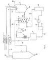
- Figur 1 das Blockdiagramm einer Anlage zur Erzeugung von Frisch- oder Synthesegas und
- Figur 2 das Blockdiagramm zur Erzeugung von Synthesegas zur Vervendung in einem Reduktions-Reaktor.
- Gemäß Figur 1 wird eine Vergasungsreaktor Kohlenstoff in Form von Kohlenstaub zugeführt. Dieser Kohlenstoff kann aber auch in Form von Gas oder Öl zugeführt werden. Dem Reaktor 9 wird weiterhin Reaktionsgas zugeführt, welches einen Teilstrom des in dem Reaktor erzeugten Gases darstellt.
- Unten aus dem Reaktor 9 wird bei Verwendung von Kohlenstaub als Kohlenstoffträger Asche 28 abgezogen und das erzeugte Gas verläßt den Reaktor mit hoher Temperatur. Das Reaktionsgas tritt dann in einen Wärmeaustauscher und Flugascheabscheider 11 ein, in welchem es abgekühlt wird. Nach Passieren eines Zyklons 14 oder eines anderen geeigneten Flugasche-Reinabscheiders wird das Reaktionsgas dann über einen Filter 15 einer Konvertierung 17 zugeführt, in welcher Wasser zugesetzt wird. Das Reaktionsgas durchläuft dann einen Wärmeaustauscher, welcher mit einem Dampferzeuger 30 gekoppelt ist und in welchem es von 400 auf 150° C heruntergekühlt wird. Ein Teilstrom des Reaktionsgases wird dann einem Kompressor 21 zugeführt und dann erneut dem Abhitze-Wärmetauscher 11 zugeführt, in welchem es aufgeheizt wird. Dieses aufgeheizte Gas wird dann dem Vergasungsreaktor 9 als Eingangsmedium wieder zugeführt, so daß für diesen Teilkreis der Kreislauf geschlossen ist.
- Das nicht dem Reaktor 9 wieder zugeführte Gas wird über einen Quenchturm 19 und einer C02 und H2S-Abscheidung 22 als Frischgas oder Synthesegas als erzeugtes Gas gewonnen.
- Die Flugasche kann nach Ausfällen von Kohlenstoff als Abfall beseitigt werden, wobei der Kohlenstoff wieder dem Reaktor 9 zugeführt werden kann.
- Gemäß Figur 2 kann das erfindungsgemäße Verfahren direkt zum Betreiben eines Reduktionsreaktors, z. B. für die Direktreduktion von Eisenerz zu Eisenschwamm benutzt werden. Der Gaserzeugungsreaktor wird in diesem Fall in gleicher Weise genutzt, wie dies gemäß Figur 1 beschrieben ist. Dem Reaktor 9 wird einmal über die Zuleitung 8 Kohlenstoff von Raumtemperatur und zum anderen über die Zuleitung 7 Sauerstoff zugeführt, während über die Leitung 6 das im Kreislauf geführte Reaktionsgas zugeführt wird. Das in dem Gaserzeugungsreaktor erzeugte Gas gelangt über die Leitung 10 in den Abhitzewärmetauscher 11, der das Gas abkühlt und der als Vorabscheider für die Flugasche dient. Nach Durchlaufen des Zyklonabscheiders 14 und des Filters 15 oder anderer geeigneter Vorrichtungsteile zur Entfernung von Feststoffen wird dann ein Teil des Gasstromes abgezweigt und dient als Oxydationsmittel in einem Erhitzer 3, welcher das aus dem eigentlichen Reduktionsreaktor 1 entströmende Gas auf die notwendige Temperatur von ca. 1100° C aufheizt.
- Das nicht in dem Abgaserhitzer 3 verwendete Gas wird einem Hochtemperatur-Konverter 17 zugeführt, aus welchem es einem Quenchturm 19 und einem Verdichter 21 zugeführt wird. Der Verdichter 21 speist die C02/H2S-Wäsche 22 und das Gas gelangt dann über die Leitung 23 wieder in den Abhitzewärmeaustauscher 11, in welchem es auf eine Temperatur von ca. 900°C aufgeheizt wird. Dieses Reaktionsgas wird dann einem Reduktionsreaktor 1 zugeführt, der weiterhin bei 27 mit Erz beschickt wird und dem bei 26 im Durchlaufverfahren das reduzierte Produkt entnommen wird. Das Gas verläßt den Reaktor 1 und wird nach der bereits genannten Aufheizung in dem Abgaserhitzer 3 dem Reaktor 9 wieder zugeführt. Für den Fachmann selbstverständlich kann dabei die hochgradige Abgas-Energie aus dem Abgas-Erhitzer 3 in einem SauerstoffVorwärmer 4 und einem Dampferzeuger 5 genutzt werden. Die Wirkungsweise des Reaktors 9 wird dabei durch den erhitzten Sauerstoff verbessert.
- Ersichtlicherweise sind in den beiden beschriebenen Kreisläufen keine Kühlungen vorhanden, ohne daß die gewonnene Energie nicht wieder in den Kreislauf zurückgespeist würde. Der Wirkungsgrad der beschriebenen Kreisläufe ist also optimal und durch die Verwendung von Kohle als Kohlenstoffträger kann das beschriebene Verfahren besonders günstig unter Bedingungen, eingesetzt werden, unter denen die Verwendung von Öl oder Erdgas nicht günstig erscheint. Das beschriebene Verfahren ist also in idealer Weise zur Lösung der anstehenden Probleme geeignet.
-
- 1 Reaktor zur Reduktion von Erzen
- 2 Abgas aus Reaktor (T = 400 - 500° C)
- 3 Abgaserhitzer
- 4 Sauerstoffvorwärmer
- 5 Dampferzeuger (zur Verwendung in C02-Wäsche und Konvertierung)
- 6 Erhitztes Abgas (T = 1000 - 1100°C)
- 7 Vorerwärmter Sauerstoff (T = 400° C)
- 8 Kohlenstoff (Kohlenstaub; 0,5 mm Trockenmahlung)
- 9 Vergasungsreaktor
- 10 Gas aus Vergasungsreaktor (Rohgas)
- 11 Abhitzewärmetauscher
- 12 Flugstaub aus Vergasungsreaktor
- 13 Gas aus Abhitzekessel
- 14 Zyklonabscheider
- 15 Filter
- 16 Brenngas (für Abgaserhitzer 3)
- 17 Hochtemperaturkonvertierung
- 18 Gas nach Konvertierung
- 19 Quenchturm und Abscheidetrommel
- 20 Reingas
- 21 Kompressor
- 22 C02-Wäsche / H2S-Wäsche
- 23 Reduktionsgas (kalt)
- 24 Reduktionsgas (heiß)
- 25 Flugstaub
- 26 Produkt aus Erzreduktion
- 27 Erzaufgabe
- 28 Asche aus Vergasungsreaktor
- 29 Erdgas (im Anfahrbetrieb)
- 30 Dampftrommel
- 31 Mantel des Vergasungsreaktors 9
- 32 Koaxiales Innenrohr (im Vergasungsreaktor 9)
- 33 zum Reaktormantel 31 gerichteter Rand des Innenrohres 32
Claims (6)
dadurch gekennzeichnet,
daß die Abwärme der Gase nach der Gasaufbereitung an das Kreislaufgas übertragen wird, und das Kreislaufgas anschließend dem Reaktor (9) zugeführt wird.
dadurch gekennzeichnet,
daß das Kreislaufgas vor dem Wiedereintritt in den Reaktor (9) teilweise oxidiert wird.
dadurch gekennzeichnet,
daß nicht umgesetzter Kohlenstoff in der Reaktorasche bzw. in der Flugasche dem Reaktor wieder zugeführt wird.
dadurch gekennzeichnet,
daß als Brennmaterial dem Reaktor Kohlenstaub, Schweröl, Erdgas oder beliebige Mischungen dieser Komponenten zugeführt werden.
gekennzeichnet durch ein zum Reaktoraußenmantel (31) koaxiales Znnenrohr (32), in dessen oberes Ende Zuführungen (6, 8) ragen und das am unteren Ende einen zum Reaktormantel (31) gerichteten Rand (33) trägt, einen im Abstand zum unteren Ende des Znnenrohres (32) angeordneten Boden mit Asche-Austragsleitung (28) und eine Abgasleitung (34) im oberen Reaktormantelbereich.
Applications Claiming Priority (2)
| Application Number | Priority Date | Filing Date | Title |
|---|---|---|---|
| DE3223702A DE3223702C2 (de) | 1982-06-25 | 1982-06-25 | Verfahren zur Erzeugung von Synthesegas und Reaktor zur Durchführung des Verfahrens |
| DE3223702 | 1982-06-25 |
Publications (3)
| Publication Number | Publication Date |
|---|---|
| EP0097803A2 EP0097803A2 (de) | 1984-01-11 |
| EP0097803A3 EP0097803A3 (en) | 1987-04-22 |
| EP0097803B1 true EP0097803B1 (de) | 1988-10-12 |
Family
ID=6166806
Family Applications (1)
| Application Number | Title | Priority Date | Filing Date |
|---|---|---|---|
| EP19830104734 Expired EP0097803B1 (de) | 1982-06-25 | 1983-05-13 | Verfahren zum Betreiben eines Reaktors zur Erzeugung von Synthesegas und Vorrichtung zur Durchführung des Verfahrens |
Country Status (7)
| Country | Link |
|---|---|
| US (1) | US4617051A (de) |
| EP (1) | EP0097803B1 (de) |
| AU (1) | AU554840B2 (de) |
| BR (1) | BR8303383A (de) |
| DE (1) | DE3223702C2 (de) |
| IN (1) | IN159054B (de) |
| ZA (1) | ZA834202B (de) |
Families Citing this family (9)
| Publication number | Priority date | Publication date | Assignee | Title |
|---|---|---|---|---|
| AU569041B2 (en) * | 1982-06-25 | 1988-01-21 | M.A.N. Maschinenfabrik Augsberg-Nurnberg Aktiengesselschaft | Production of synthesis gas and subsequent treatment of the gas |
| DE3237334A1 (de) * | 1982-10-08 | 1984-04-12 | M.A.N. Maschinenfabrik Augsburg-Nürnberg AG, 4200 Oberhausen | Verfahren zum betreiben eines reaktors zur erzeugung von synthesegas und vorrichtung zur durchfuehrung des verfahrens |
| DE3439487A1 (de) * | 1984-10-27 | 1986-06-26 | M.A.N. Maschinenfabrik Augsburg-Nürnberg AG, 4200 Oberhausen | Energieguenstiges verfahren zur erzeugung von synthesegas mit einem hohen methangehalt |
| DE3827702A1 (de) * | 1988-08-16 | 1990-02-22 | Uhde Gmbh | Verfahren und vorrichtung zur reinigung von rohgas aus einer feststoff-vergasung |
| DE3922612C2 (de) * | 1989-07-10 | 1998-07-02 | Krupp Koppers Gmbh | Verfahren zur Erzeugung von Methanol-Synthesegas |
| US6149859A (en) * | 1997-11-03 | 2000-11-21 | Texaco Inc. | Gasification plant for direct reduction reactors |
| RU2129462C1 (ru) * | 1998-08-31 | 1999-04-27 | Институт нефтехимического синтеза им.А.В.Топчиева РАН | Химический реактор сжатия для получения синтез-газа |
| DE10334590B4 (de) * | 2003-07-28 | 2006-10-26 | Uhde Gmbh | Verfahren zur Gewinnung von Wasserstoff aus einem methanhaltigen Gas, insbesondere Erdgas und Anlage zur Durchführung des Verfahrens |
| ES3055228T3 (en) * | 2018-03-30 | 2026-02-10 | Tata Steel Nederland Tech Bv | Method for off-gas composition control in a metal smelting apparatus |
Family Cites Families (14)
| Publication number | Priority date | Publication date | Assignee | Title |
|---|---|---|---|---|
| US2113774A (en) * | 1934-11-26 | 1938-04-12 | Schmalfeldt Hans | Process for the gasification of dust or fine-grained fuels with circulating gas |
| DE905974C (de) * | 1951-09-13 | 1954-03-08 | Demag Ag | Verfahren und Vorrichtung zur Herstellung von Gasen mit einem bestimmten Kohlenoxyd-Wasserstoff-Verhaeltnis, insbesondere fuer die Erzreduktion |
| GB799551A (en) * | 1956-02-06 | 1958-08-13 | Texaco Development Corp | Reduction of a metal oxide with carbon monoxide and hydrogen |
| NL223944A (de) * | 1957-01-15 | 1900-01-01 | ||
| US3193378A (en) * | 1964-03-16 | 1965-07-06 | Exxon Research Engineering Co | Process for reduction of iron ore |
| GB1408560A (en) * | 1971-11-26 | 1975-10-01 | Shell Int Research | Process for the production of hydrogenrich gas |
| SU508527A1 (ru) * | 1974-06-14 | 1976-03-30 | Государственный Ордена Ленина Союз-Ный Институт По Проектированию Метал-Лургических Заводов | Способ получени восстановительногогаза |
| GB1566698A (en) * | 1975-09-05 | 1980-05-08 | Foster Wheeler Ltd | Treatment of gases containing hydrogen and carbon monoxide |
| US4011058A (en) * | 1975-10-01 | 1977-03-08 | Phillips Petroleum Company | Production of substitute natural gas from gasification of coal char |
| DE2733785A1 (de) * | 1977-07-27 | 1979-02-08 | Didier Eng | Verfahren zur weiterverarbeitung von koksofengas |
| DE2821413A1 (de) * | 1978-05-16 | 1979-11-22 | Texaco Development Corp | Teiloxydationsverfahren |
| DE2908771C2 (de) * | 1979-03-06 | 1984-07-12 | Kraftwerk Union AG, 4330 Mülheim | Kombinierte Anlage zur Vergasung von Kohle und zur Reduktion von Metallerzen |
| DK148915C (da) * | 1980-03-21 | 1986-06-02 | Haldor Topsoe As | Fremgangsmaade til fremstilling af hydrogen eller ammoniaksyntesegas |
| GB2078251B (en) * | 1980-06-19 | 1984-02-15 | Gen Electric | System for gasifying coal and reforming gaseous products thereof |
-
1982
- 1982-06-25 DE DE3223702A patent/DE3223702C2/de not_active Expired
-
1983
- 1983-05-13 EP EP19830104734 patent/EP0097803B1/de not_active Expired
- 1983-06-02 AU AU15324/83A patent/AU554840B2/en not_active Ceased
- 1983-06-08 ZA ZA834202A patent/ZA834202B/xx unknown
- 1983-06-17 US US06/505,330 patent/US4617051A/en not_active Expired - Lifetime
- 1983-06-24 BR BR8303383A patent/BR8303383A/pt not_active IP Right Cessation
- 1983-06-25 IN IN793/CAL/83A patent/IN159054B/en unknown
Also Published As
| Publication number | Publication date |
|---|---|
| AU1532483A (en) | 1984-01-05 |
| US4617051A (en) | 1986-10-14 |
| DE3223702C2 (de) | 1984-06-28 |
| EP0097803A3 (en) | 1987-04-22 |
| ZA834202B (en) | 1984-03-28 |
| EP0097803A2 (de) | 1984-01-11 |
| AU554840B2 (en) | 1986-09-04 |
| BR8303383A (pt) | 1984-02-07 |
| DE3223702A1 (de) | 1983-12-29 |
| IN159054B (de) | 1987-03-14 |
Similar Documents
| Publication | Publication Date | Title |
|---|---|---|
| DE69401975T2 (de) | Teiloxidation für Energieversorgungssystem | |
| AT507113A1 (de) | Verfahren und anlage zur energie- und co2-emissionsoptimierten eisenerzeugung | |
| EP0498289A1 (de) | Verfahren zur Trocknung von Kohle für Einschmelz- bzw. Kohlevergaser | |
| AT406380B (de) | Verfahren zum herstellen von flüssigem roheisen oder flüssigen stahlvorprodukten sowie anlage zur durchführung des verfahrens | |
| DE3008445C2 (de) | Verfahren und Vorrichtung zum Reduzieren eines teilchenförmigen Erzes zu Metallpartikeln | |
| DE3223702C2 (de) | Verfahren zur Erzeugung von Synthesegas und Reaktor zur Durchführung des Verfahrens | |
| DE2345396C3 (de) | Verfahren zum Erzeugen elektrischer Energie | |
| EP0014488A1 (de) | Verfahren zur Erzeugung von wasserstoff- und kohlenmonoxydhaltigen Gasen | |
| EP0108198B1 (de) | Verfahren zum Betreiben eines Reaktors zur Erzeugung von Synthesegas und Vorrichtung zur Durchführung des Verfahrens | |
| DE3404684A1 (de) | Verfahren zur nutzung der beim trockenkuehlen von koks mittels eines gases anfallenden fuehlbaren waerme | |
| DE2947128C2 (de) | Verfahren zur kontinuierlichen Erzeugung eines Hochtemperatur-Reduktionsgases | |
| DE3044989C2 (de) | Verfahren zur trockenen Kokskühlung | |
| DE3414140A1 (de) | Verfahren und vorrichtung zum betreiben eines vergasungsreaktors | |
| DE874297C (de) | Verfahren zur Umsetzung kohlenoxydhaltiger Gasgemische mit Wasserdampf | |
| EP0016179A1 (de) | Anlage zur Kohlevergasung. | |
| EP0035783B1 (de) | Verfahren und Vorrichtung zur Strom- und Wärmeerzeugung aus Brennstoffen | |
| DE680605C (de) | Verfahren zur Herstellung von Eisenschwamm | |
| DE2724833A1 (de) | Kohlevergasung mit kernenergie | |
| DE112010005234T5 (de) | Energierückgewinnung aus Gasen in einer Hochofenanlage | |
| EP0016214B1 (de) | Anlage zur kohlevergasung mit hydrierendem und wasserdampfvergaser | |
| EP0016178B1 (de) | Anlage zur Kohlevergasung | |
| DE2408461A1 (de) | Verfahren und anlage zur erzeugung von synthesegas unter anwendung eines koksbeschickten abstichgenerators | |
| EP0318694A2 (de) | Verfahren zur Hydrierung fester kohlenstoffhaltiger Einsatzstoffe | |
| DE2724802A1 (de) | Kohlevergasung mit kernenergie | |
| AT409386B (de) | Verfahren und anlage zur direktreduktion von teilchenförmigen oxidhältigen erzen |
Legal Events
| Date | Code | Title | Description |
|---|---|---|---|
| PUAI | Public reference made under article 153(3) epc to a published international application that has entered the european phase |
Free format text: ORIGINAL CODE: 0009012 |
|
| AK | Designated contracting states |
Designated state(s): BE FR GB IT NL |
|
| 17P | Request for examination filed |
Effective date: 19840306 |
|
| RAP1 | Party data changed (applicant data changed or rights of an application transferred) |
Owner name: M.A.N. MASCHINENFABRIK AUGSBURG-NUERNBERG AKTIENGE |
|
| RAP1 | Party data changed (applicant data changed or rights of an application transferred) |
Owner name: MAN GUTEHOFFNUNGSHUETTE GMBH |
|
| PUAL | Search report despatched |
Free format text: ORIGINAL CODE: 0009013 |
|
| AK | Designated contracting states |
Kind code of ref document: A3 Designated state(s): BE FR GB IT NL |
|
| 17Q | First examination report despatched |
Effective date: 19871221 |
|
| GRAA | (expected) grant |
Free format text: ORIGINAL CODE: 0009210 |
|
| AK | Designated contracting states |
Kind code of ref document: B1 Designated state(s): BE FR GB IT NL |
|
| ITF | It: translation for a ep patent filed | ||
| ET | Fr: translation filed | ||
| GBT | Gb: translation of ep patent filed (gb section 77(6)(a)/1977) | ||
| RAP2 | Party data changed (patent owner data changed or rights of a patent transferred) |
Owner name: MAN GUTEHOFFNUNGSHUETTE AKTIENGESELLSCHAFT |
|
| NLT2 | Nl: modifications (of names), taken from the european patent patent bulletin |
Owner name: MAN GUTEHOFFNUNGSHUETTE AKTIENGESELLSCHAFT TE OBER |
|
| PLBE | No opposition filed within time limit |
Free format text: ORIGINAL CODE: 0009261 |
|
| STAA | Information on the status of an ep patent application or granted ep patent |
Free format text: STATUS: NO OPPOSITION FILED WITHIN TIME LIMIT |
|
| 26N | No opposition filed | ||
| BECN | Be: change of holder's name |
Effective date: 19881012 |
|
| ITTA | It: last paid annual fee | ||
| PGFP | Annual fee paid to national office [announced via postgrant information from national office to epo] |
Ref country code: GB Payment date: 19980414 Year of fee payment: 16 |
|
| PGFP | Annual fee paid to national office [announced via postgrant information from national office to epo] |
Ref country code: FR Payment date: 19980417 Year of fee payment: 16 |
|
| PGFP | Annual fee paid to national office [announced via postgrant information from national office to epo] |
Ref country code: BE Payment date: 19980427 Year of fee payment: 16 |
|
| PGFP | Annual fee paid to national office [announced via postgrant information from national office to epo] |
Ref country code: NL Payment date: 19980430 Year of fee payment: 16 |
|
| PG25 | Lapsed in a contracting state [announced via postgrant information from national office to epo] |
Ref country code: GB Free format text: LAPSE BECAUSE OF NON-PAYMENT OF DUE FEES Effective date: 19990513 |
|
| PG25 | Lapsed in a contracting state [announced via postgrant information from national office to epo] |
Ref country code: BE Free format text: LAPSE BECAUSE OF NON-PAYMENT OF DUE FEES Effective date: 19990531 |
|
| BERE | Be: lapsed |
Owner name: MAN GUTEHOFFNUNGSHUTTE A.G. Effective date: 19990531 |
|
| PG25 | Lapsed in a contracting state [announced via postgrant information from national office to epo] |
Ref country code: NL Free format text: LAPSE BECAUSE OF NON-PAYMENT OF DUE FEES Effective date: 19991201 |
|
| GBPC | Gb: european patent ceased through non-payment of renewal fee |
Effective date: 19990513 |
|
| PG25 | Lapsed in a contracting state [announced via postgrant information from national office to epo] |
Ref country code: FR Free format text: LAPSE BECAUSE OF NON-PAYMENT OF DUE FEES Effective date: 20000131 |
|
| NLV4 | Nl: lapsed or anulled due to non-payment of the annual fee |
Effective date: 19991201 |
|
| REG | Reference to a national code |
Ref country code: FR Ref legal event code: ST |