EP0097770B1 - Oxygen gas permselective membrane - Google Patents
Oxygen gas permselective membrane Download PDFInfo
- Publication number
- EP0097770B1 EP0097770B1 EP83102715A EP83102715A EP0097770B1 EP 0097770 B1 EP0097770 B1 EP 0097770B1 EP 83102715 A EP83102715 A EP 83102715A EP 83102715 A EP83102715 A EP 83102715A EP 0097770 B1 EP0097770 B1 EP 0097770B1
- Authority
- EP
- European Patent Office
- Prior art keywords
- membrane
- film
- oxygen gas
- oxide
- water repellent
- Prior art date
- Legal status (The legal status is an assumption and is not a legal conclusion. Google has not performed a legal analysis and makes no representation as to the accuracy of the status listed.)
- Expired - Lifetime
Links
- 239000012528 membrane Substances 0.000 title claims description 107
- MYMOFIZGZYHOMD-UHFFFAOYSA-N Dioxygen Chemical compound O=O MYMOFIZGZYHOMD-UHFFFAOYSA-N 0.000 title claims description 44
- 229910001882 dioxygen Inorganic materials 0.000 title claims description 44
- XLYOFNOQVPJJNP-UHFFFAOYSA-N water Substances O XLYOFNOQVPJJNP-UHFFFAOYSA-N 0.000 claims description 61
- 229910044991 metal oxide Inorganic materials 0.000 claims description 47
- 239000011148 porous material Substances 0.000 claims description 41
- 230000002940 repellent Effects 0.000 claims description 41
- 239000005871 repellent Substances 0.000 claims description 41
- 238000004544 sputter deposition Methods 0.000 claims description 27
- 238000000034 method Methods 0.000 claims description 26
- 230000008569 process Effects 0.000 claims description 15
- 238000005137 deposition process Methods 0.000 claims description 13
- XOLBLPGZBRYERU-UHFFFAOYSA-N tin dioxide Chemical compound O=[Sn]=O XOLBLPGZBRYERU-UHFFFAOYSA-N 0.000 claims description 10
- VYPSYNLAJGMNEJ-UHFFFAOYSA-N Silicium dioxide Chemical compound O=[Si]=O VYPSYNLAJGMNEJ-UHFFFAOYSA-N 0.000 claims description 5
- GWEVSGVZZGPLCZ-UHFFFAOYSA-N Titan oxide Chemical compound O=[Ti]=O GWEVSGVZZGPLCZ-UHFFFAOYSA-N 0.000 claims description 5
- 238000006116 polymerization reaction Methods 0.000 claims description 5
- 150000002894 organic compounds Chemical class 0.000 claims description 4
- XLOMVQKBTHCTTD-UHFFFAOYSA-N Zinc monoxide Chemical compound [Zn]=O XLOMVQKBTHCTTD-UHFFFAOYSA-N 0.000 claims description 3
- QVQLCTNNEUAWMS-UHFFFAOYSA-N barium oxide Chemical compound [Ba]=O QVQLCTNNEUAWMS-UHFFFAOYSA-N 0.000 claims description 3
- 239000000395 magnesium oxide Substances 0.000 claims description 3
- CPLXHLVBOLITMK-UHFFFAOYSA-N magnesium oxide Inorganic materials [Mg]=O CPLXHLVBOLITMK-UHFFFAOYSA-N 0.000 claims description 3
- AXZKOIWUVFPNLO-UHFFFAOYSA-N magnesium;oxygen(2-) Chemical compound [O-2].[Mg+2] AXZKOIWUVFPNLO-UHFFFAOYSA-N 0.000 claims description 3
- ODINCKMPIJJUCX-UHFFFAOYSA-N calcium oxide Inorganic materials [Ca]=O ODINCKMPIJJUCX-UHFFFAOYSA-N 0.000 claims description 2
- TWNQGVIAIRXVLR-UHFFFAOYSA-N oxo(oxoalumanyloxy)alumane Chemical compound O=[Al]O[Al]=O TWNQGVIAIRXVLR-UHFFFAOYSA-N 0.000 claims description 2
- 239000000377 silicon dioxide Substances 0.000 claims description 2
- 235000012239 silicon dioxide Nutrition 0.000 claims description 2
- 239000004408 titanium dioxide Substances 0.000 claims description 2
- IATRAKWUXMZMIY-UHFFFAOYSA-N strontium oxide Chemical compound [O-2].[Sr+2] IATRAKWUXMZMIY-UHFFFAOYSA-N 0.000 claims 2
- 230000015572 biosynthetic process Effects 0.000 claims 1
- BRPQOXSCLDDYGP-UHFFFAOYSA-N calcium oxide Chemical compound [O-2].[Ca+2] BRPQOXSCLDDYGP-UHFFFAOYSA-N 0.000 claims 1
- 239000000292 calcium oxide Substances 0.000 claims 1
- 239000011787 zinc oxide Substances 0.000 claims 1
- 239000010410 layer Substances 0.000 description 73
- 239000010408 film Substances 0.000 description 47
- KDLHZDBZIXYQEI-UHFFFAOYSA-N Palladium Chemical compound [Pd] KDLHZDBZIXYQEI-UHFFFAOYSA-N 0.000 description 30
- 239000007789 gas Substances 0.000 description 27
- CURLTUGMZLYLDI-UHFFFAOYSA-N Carbon dioxide Chemical compound O=C=O CURLTUGMZLYLDI-UHFFFAOYSA-N 0.000 description 24
- PXHVJJICTQNCMI-UHFFFAOYSA-N Nickel Chemical compound [Ni] PXHVJJICTQNCMI-UHFFFAOYSA-N 0.000 description 23
- -1 polytetrafluoroethylene Polymers 0.000 description 21
- QVGXLLKOCUKJST-UHFFFAOYSA-N atomic oxygen Chemical compound [O] QVGXLLKOCUKJST-UHFFFAOYSA-N 0.000 description 20
- 239000000463 material Substances 0.000 description 20
- 239000001301 oxygen Substances 0.000 description 20
- 229910052760 oxygen Inorganic materials 0.000 description 20
- 238000000151 deposition Methods 0.000 description 19
- XKRFYHLGVUSROY-UHFFFAOYSA-N Argon Chemical compound [Ar] XKRFYHLGVUSROY-UHFFFAOYSA-N 0.000 description 18
- 229910002092 carbon dioxide Inorganic materials 0.000 description 18
- 239000007868 Raney catalyst Substances 0.000 description 17
- 229910000564 Raney nickel Inorganic materials 0.000 description 17
- 239000003792 electrolyte Substances 0.000 description 15
- 229910052763 palladium Inorganic materials 0.000 description 15
- 230000000052 comparative effect Effects 0.000 description 14
- 239000004417 polycarbonate Substances 0.000 description 14
- 229920000515 polycarbonate Polymers 0.000 description 14
- 239000001569 carbon dioxide Substances 0.000 description 12
- 239000002131 composite material Substances 0.000 description 12
- 230000008021 deposition Effects 0.000 description 10
- 229910052786 argon Inorganic materials 0.000 description 9
- 229910052751 metal Inorganic materials 0.000 description 9
- 239000002184 metal Substances 0.000 description 9
- 239000012466 permeate Substances 0.000 description 9
- OKTJSMMVPCPJKN-UHFFFAOYSA-N Carbon Chemical compound [C] OKTJSMMVPCPJKN-UHFFFAOYSA-N 0.000 description 8
- 229920001343 polytetrafluoroethylene Polymers 0.000 description 8
- 239000004810 polytetrafluoroethylene Substances 0.000 description 8
- 229910052725 zinc Inorganic materials 0.000 description 8
- 239000011701 zinc Substances 0.000 description 8
- 239000004743 Polypropylene Substances 0.000 description 7
- 230000000694 effects Effects 0.000 description 7
- PIBWKRNGBLPSSY-UHFFFAOYSA-L palladium(II) chloride Chemical compound Cl[Pd]Cl PIBWKRNGBLPSSY-UHFFFAOYSA-L 0.000 description 7
- 229920001155 polypropylene Polymers 0.000 description 7
- 239000000843 powder Substances 0.000 description 7
- 239000000047 product Substances 0.000 description 7
- 230000009467 reduction Effects 0.000 description 7
- KWYUFKZDYYNOTN-UHFFFAOYSA-M Potassium hydroxide Chemical compound [OH-].[K+] KWYUFKZDYYNOTN-UHFFFAOYSA-M 0.000 description 6
- 230000010287 polarization Effects 0.000 description 6
- 239000004698 Polyethylene Substances 0.000 description 5
- 229920000573 polyethylene Polymers 0.000 description 5
- 239000011347 resin Substances 0.000 description 5
- 229920005989 resin Polymers 0.000 description 5
- 238000003860 storage Methods 0.000 description 5
- BQCADISMDOOEFD-UHFFFAOYSA-N Silver Chemical compound [Ag] BQCADISMDOOEFD-UHFFFAOYSA-N 0.000 description 4
- 238000006243 chemical reaction Methods 0.000 description 4
- 238000010438 heat treatment Methods 0.000 description 4
- 229910052709 silver Inorganic materials 0.000 description 4
- 239000004332 silver Substances 0.000 description 4
- LVJZCPNIJXVIAT-UHFFFAOYSA-N 1-ethenyl-2,3,4,5,6-pentafluorobenzene Chemical compound FC1=C(F)C(F)=C(C=C)C(F)=C1F LVJZCPNIJXVIAT-UHFFFAOYSA-N 0.000 description 3
- WMFOQBRAJBCJND-UHFFFAOYSA-M Lithium hydroxide Chemical compound [Li+].[OH-] WMFOQBRAJBCJND-UHFFFAOYSA-M 0.000 description 3
- HEMHJVSKTPXQMS-UHFFFAOYSA-M Sodium hydroxide Chemical compound [OH-].[Na+] HEMHJVSKTPXQMS-UHFFFAOYSA-M 0.000 description 3
- HCHKCACWOHOZIP-UHFFFAOYSA-N Zinc Chemical group [Zn] HCHKCACWOHOZIP-UHFFFAOYSA-N 0.000 description 3
- 239000006096 absorbing agent Substances 0.000 description 3
- 229910052782 aluminium Inorganic materials 0.000 description 3
- 229910052788 barium Inorganic materials 0.000 description 3
- 239000011230 binding agent Substances 0.000 description 3
- 229910052791 calcium Inorganic materials 0.000 description 3
- 239000011575 calcium Substances 0.000 description 3
- 229920002678 cellulose Polymers 0.000 description 3
- MSKQYWJTFPOQAV-UHFFFAOYSA-N fluoroethene;prop-1-ene Chemical group CC=C.FC=C MSKQYWJTFPOQAV-UHFFFAOYSA-N 0.000 description 3
- 150000002430 hydrocarbons Chemical class 0.000 description 3
- 229910052749 magnesium Inorganic materials 0.000 description 3
- 239000011777 magnesium Substances 0.000 description 3
- 238000004519 manufacturing process Methods 0.000 description 3
- 238000005259 measurement Methods 0.000 description 3
- 150000002739 metals Chemical class 0.000 description 3
- 239000000203 mixture Substances 0.000 description 3
- 229910052759 nickel Inorganic materials 0.000 description 3
- 230000035699 permeability Effects 0.000 description 3
- 229920001296 polysiloxane Polymers 0.000 description 3
- 229910052710 silicon Inorganic materials 0.000 description 3
- 229910052712 strontium Inorganic materials 0.000 description 3
- 229910052718 tin Inorganic materials 0.000 description 3
- 239000010936 titanium Substances 0.000 description 3
- 229910052719 titanium Inorganic materials 0.000 description 3
- NLXLAEXVIDQMFP-UHFFFAOYSA-N Ammonia chloride Chemical compound [NH4+].[Cl-] NLXLAEXVIDQMFP-UHFFFAOYSA-N 0.000 description 2
- UXVMQQNJUSDDNG-UHFFFAOYSA-L Calcium chloride Chemical compound [Cl-].[Cl-].[Ca+2] UXVMQQNJUSDDNG-UHFFFAOYSA-L 0.000 description 2
- 229920013683 Celanese Polymers 0.000 description 2
- WSFSSNUMVMOOMR-UHFFFAOYSA-N Formaldehyde Chemical compound O=C WSFSSNUMVMOOMR-UHFFFAOYSA-N 0.000 description 2
- 239000004721 Polyphenylene oxide Substances 0.000 description 2
- 239000004734 Polyphenylene sulfide Substances 0.000 description 2
- PPBRXRYQALVLMV-UHFFFAOYSA-N Styrene Chemical compound C=CC1=CC=CC=C1 PPBRXRYQALVLMV-UHFFFAOYSA-N 0.000 description 2
- 230000009286 beneficial effect Effects 0.000 description 2
- 239000001110 calcium chloride Substances 0.000 description 2
- 229910001628 calcium chloride Inorganic materials 0.000 description 2
- 229910052799 carbon Inorganic materials 0.000 description 2
- 238000010227 cup method (microbiological evaluation) Methods 0.000 description 2
- 238000009792 diffusion process Methods 0.000 description 2
- 239000006185 dispersion Substances 0.000 description 2
- 229920000840 ethylene tetrafluoroethylene copolymer Polymers 0.000 description 2
- 239000000446 fuel Substances 0.000 description 2
- ZQBFAOFFOQMSGJ-UHFFFAOYSA-N hexafluorobenzene Chemical compound FC1=C(F)C(F)=C(F)C(F)=C1F ZQBFAOFFOQMSGJ-UHFFFAOYSA-N 0.000 description 2
- XLYOFNOQVPJJNP-UHFFFAOYSA-M hydroxide Chemical compound [OH-] XLYOFNOQVPJJNP-UHFFFAOYSA-M 0.000 description 2
- 238000012423 maintenance Methods 0.000 description 2
- 239000004745 nonwoven fabric Substances 0.000 description 2
- 150000004812 organic fluorine compounds Chemical class 0.000 description 2
- 230000003647 oxidation Effects 0.000 description 2
- 238000007254 oxidation reaction Methods 0.000 description 2
- 239000004033 plastic Substances 0.000 description 2
- 229920003023 plastic Polymers 0.000 description 2
- BASFCYQUMIYNBI-UHFFFAOYSA-N platinum Chemical compound [Pt] BASFCYQUMIYNBI-UHFFFAOYSA-N 0.000 description 2
- 229920006380 polyphenylene oxide Polymers 0.000 description 2
- 229920000069 polyphenylene sulfide Polymers 0.000 description 2
- 230000002035 prolonged effect Effects 0.000 description 2
- 238000005096 rolling process Methods 0.000 description 2
- CPRMKOQKXYSDML-UHFFFAOYSA-M rubidium hydroxide Chemical compound [OH-].[Rb+] CPRMKOQKXYSDML-UHFFFAOYSA-M 0.000 description 2
- 239000002356 single layer Substances 0.000 description 2
- 229910001220 stainless steel Inorganic materials 0.000 description 2
- 239000010935 stainless steel Substances 0.000 description 2
- 239000000126 substance Substances 0.000 description 2
- 238000012360 testing method Methods 0.000 description 2
- GETTZEONDQJALK-UHFFFAOYSA-N (trifluoromethyl)benzene Chemical compound FC(F)(F)C1=CC=CC=C1 GETTZEONDQJALK-UHFFFAOYSA-N 0.000 description 1
- WACNXHCZHTVBJM-UHFFFAOYSA-N 1,2,3,4,5-pentafluorobenzene Chemical compound FC1=CC(F)=C(F)C(F)=C1F WACNXHCZHTVBJM-UHFFFAOYSA-N 0.000 description 1
- YTCGOUNVIAWCMG-UHFFFAOYSA-N 1-chloro-3-(trifluoromethyl)benzene Chemical compound FC(F)(F)C1=CC=CC(Cl)=C1 YTCGOUNVIAWCMG-UHFFFAOYSA-N 0.000 description 1
- MFGOFGRYDNHJTA-UHFFFAOYSA-N 2-amino-1-(2-fluorophenyl)ethanol Chemical compound NCC(O)C1=CC=CC=C1F MFGOFGRYDNHJTA-UHFFFAOYSA-N 0.000 description 1
- 229920000049 Carbon (fiber) Polymers 0.000 description 1
- 239000004215 Carbon black (E152) Substances 0.000 description 1
- BVKZGUZCCUSVTD-UHFFFAOYSA-L Carbonate Chemical compound [O-]C([O-])=O BVKZGUZCCUSVTD-UHFFFAOYSA-L 0.000 description 1
- YCKRFDGAMUMZLT-UHFFFAOYSA-N Fluorine atom Chemical compound [F] YCKRFDGAMUMZLT-UHFFFAOYSA-N 0.000 description 1
- UFHFLCQGNIYNRP-UHFFFAOYSA-N Hydrogen Chemical compound [H][H] UFHFLCQGNIYNRP-UHFFFAOYSA-N 0.000 description 1
- 239000004952 Polyamide Substances 0.000 description 1
- 230000009471 action Effects 0.000 description 1
- 229910052784 alkaline earth metal Inorganic materials 0.000 description 1
- 150000001342 alkaline earth metals Chemical class 0.000 description 1
- XYLMUPLGERFSHI-UHFFFAOYSA-N alpha-Methylstyrene Chemical compound CC(=C)C1=CC=CC=C1 XYLMUPLGERFSHI-UHFFFAOYSA-N 0.000 description 1
- 235000019270 ammonium chloride Nutrition 0.000 description 1
- 229910021383 artificial graphite Inorganic materials 0.000 description 1
- 238000005452 bending Methods 0.000 description 1
- HUCVOHYBFXVBRW-UHFFFAOYSA-M caesium hydroxide Inorganic materials [OH-].[Cs+] HUCVOHYBFXVBRW-UHFFFAOYSA-M 0.000 description 1
- 230000008859 change Effects 0.000 description 1
- 239000003795 chemical substances by application Substances 0.000 description 1
- 229910017052 cobalt Inorganic materials 0.000 description 1
- 239000010941 cobalt Substances 0.000 description 1
- 150000001875 compounds Chemical class 0.000 description 1
- 239000012141 concentrate Substances 0.000 description 1
- 229920001577 copolymer Polymers 0.000 description 1
- 238000013461 design Methods 0.000 description 1
- 230000006866 deterioration Effects 0.000 description 1
- QLTKZXWDJGMCAR-UHFFFAOYSA-N dioxido(dioxo)tungsten;nickel(2+) Chemical compound [Ni+2].[O-][W]([O-])(=O)=O QLTKZXWDJGMCAR-UHFFFAOYSA-N 0.000 description 1
- 238000003411 electrode reaction Methods 0.000 description 1
- 239000004744 fabric Substances 0.000 description 1
- 239000000835 fiber Substances 0.000 description 1
- 239000011737 fluorine Substances 0.000 description 1
- 229910052731 fluorine Inorganic materials 0.000 description 1
- PCHJSUWPFVWCPO-UHFFFAOYSA-N gold Chemical compound [Au] PCHJSUWPFVWCPO-UHFFFAOYSA-N 0.000 description 1
- 229910052737 gold Inorganic materials 0.000 description 1
- 239000010931 gold Substances 0.000 description 1
- 229930195733 hydrocarbon Natural products 0.000 description 1
- 239000001257 hydrogen Substances 0.000 description 1
- 229910052739 hydrogen Inorganic materials 0.000 description 1
- 125000002887 hydroxy group Chemical group [H]O* 0.000 description 1
- 230000002401 inhibitory effect Effects 0.000 description 1
- 230000003993 interaction Effects 0.000 description 1
- XEEYBQQBJWHFJM-UHFFFAOYSA-N iron Substances [Fe] XEEYBQQBJWHFJM-UHFFFAOYSA-N 0.000 description 1
- 229910052742 iron Inorganic materials 0.000 description 1
- YADSGOSSYOOKMP-UHFFFAOYSA-N lead dioxide Inorganic materials O=[Pb]=O YADSGOSSYOOKMP-UHFFFAOYSA-N 0.000 description 1
- 239000000314 lubricant Substances 0.000 description 1
- QSHDDOUJBYECFT-UHFFFAOYSA-N mercury Chemical compound [Hg] QSHDDOUJBYECFT-UHFFFAOYSA-N 0.000 description 1
- 229910052753 mercury Inorganic materials 0.000 description 1
- VNWKTOKETHGBQD-UHFFFAOYSA-N methane Chemical compound C VNWKTOKETHGBQD-UHFFFAOYSA-N 0.000 description 1
- 239000000178 monomer Substances 0.000 description 1
- 239000003921 oil Substances 0.000 description 1
- 230000033116 oxidation-reduction process Effects 0.000 description 1
- UFQXGXDIJMBKTC-UHFFFAOYSA-N oxostrontium Chemical compound [Sr]=O UFQXGXDIJMBKTC-UHFFFAOYSA-N 0.000 description 1
- 239000002245 particle Substances 0.000 description 1
- 238000002161 passivation Methods 0.000 description 1
- 238000007747 plating Methods 0.000 description 1
- 229910052697 platinum Inorganic materials 0.000 description 1
- 229920002647 polyamide Polymers 0.000 description 1
- 229920000642 polymer Polymers 0.000 description 1
- 239000011369 resultant mixture Substances 0.000 description 1
- 229920006395 saturated elastomer Polymers 0.000 description 1
- 229930195734 saturated hydrocarbon Natural products 0.000 description 1
- 229910052596 spinel Inorganic materials 0.000 description 1
- 239000011029 spinel Substances 0.000 description 1
- 238000007669 thermal treatment Methods 0.000 description 1
- 239000010409 thin film Substances 0.000 description 1
- 229910052721 tungsten Inorganic materials 0.000 description 1
- UONOETXJSWQNOL-UHFFFAOYSA-N tungsten carbide Chemical compound [W+]#[C-] UONOETXJSWQNOL-UHFFFAOYSA-N 0.000 description 1
- 229930195735 unsaturated hydrocarbon Natural products 0.000 description 1
- 238000001771 vacuum deposition Methods 0.000 description 1
Classifications
-
- B—PERFORMING OPERATIONS; TRANSPORTING
- B01—PHYSICAL OR CHEMICAL PROCESSES OR APPARATUS IN GENERAL
- B01D—SEPARATION
- B01D67/00—Processes specially adapted for manufacturing semi-permeable membranes for separation processes or apparatus
- B01D67/0039—Inorganic membrane manufacture
- B01D67/0072—Inorganic membrane manufacture by deposition from the gaseous phase, e.g. sputtering, CVD, PVD
-
- B—PERFORMING OPERATIONS; TRANSPORTING
- B01—PHYSICAL OR CHEMICAL PROCESSES OR APPARATUS IN GENERAL
- B01D—SEPARATION
- B01D67/00—Processes specially adapted for manufacturing semi-permeable membranes for separation processes or apparatus
- B01D67/0039—Inorganic membrane manufacture
- B01D67/0069—Inorganic membrane manufacture by deposition from the liquid phase, e.g. electrochemical deposition
-
- B—PERFORMING OPERATIONS; TRANSPORTING
- B01—PHYSICAL OR CHEMICAL PROCESSES OR APPARATUS IN GENERAL
- B01D—SEPARATION
- B01D71/00—Semi-permeable membranes for separation processes or apparatus characterised by the material; Manufacturing processes specially adapted therefor
- B01D71/02—Inorganic material
- B01D71/024—Oxides
-
- G—PHYSICS
- G01—MEASURING; TESTING
- G01N—INVESTIGATING OR ANALYSING MATERIALS BY DETERMINING THEIR CHEMICAL OR PHYSICAL PROPERTIES
- G01N27/00—Investigating or analysing materials by the use of electric, electrochemical, or magnetic means
- G01N27/26—Investigating or analysing materials by the use of electric, electrochemical, or magnetic means by investigating electrochemical variables; by using electrolysis or electrophoresis
- G01N27/28—Electrolytic cell components
- G01N27/40—Semi-permeable membranes or partitions
-
- H—ELECTRICITY
- H01—ELECTRIC ELEMENTS
- H01M—PROCESSES OR MEANS, e.g. BATTERIES, FOR THE DIRECT CONVERSION OF CHEMICAL ENERGY INTO ELECTRICAL ENERGY
- H01M4/00—Electrodes
- H01M4/86—Inert electrodes with catalytic activity, e.g. for fuel cells
-
- B—PERFORMING OPERATIONS; TRANSPORTING
- B01—PHYSICAL OR CHEMICAL PROCESSES OR APPARATUS IN GENERAL
- B01D—SEPARATION
- B01D2325/00—Details relating to properties of membranes
- B01D2325/04—Characteristic thickness
-
- Y—GENERAL TAGGING OF NEW TECHNOLOGICAL DEVELOPMENTS; GENERAL TAGGING OF CROSS-SECTIONAL TECHNOLOGIES SPANNING OVER SEVERAL SECTIONS OF THE IPC; TECHNICAL SUBJECTS COVERED BY FORMER USPC CROSS-REFERENCE ART COLLECTIONS [XRACs] AND DIGESTS
- Y02—TECHNOLOGIES OR APPLICATIONS FOR MITIGATION OR ADAPTATION AGAINST CLIMATE CHANGE
- Y02E—REDUCTION OF GREENHOUSE GAS [GHG] EMISSIONS, RELATED TO ENERGY GENERATION, TRANSMISSION OR DISTRIBUTION
- Y02E60/00—Enabling technologies; Technologies with a potential or indirect contribution to GHG emissions mitigation
- Y02E60/30—Hydrogen technology
- Y02E60/50—Fuel cells
-
- Y—GENERAL TAGGING OF NEW TECHNOLOGICAL DEVELOPMENTS; GENERAL TAGGING OF CROSS-SECTIONAL TECHNOLOGIES SPANNING OVER SEVERAL SECTIONS OF THE IPC; TECHNICAL SUBJECTS COVERED BY FORMER USPC CROSS-REFERENCE ART COLLECTIONS [XRACs] AND DIGESTS
- Y10—TECHNICAL SUBJECTS COVERED BY FORMER USPC
- Y10T—TECHNICAL SUBJECTS COVERED BY FORMER US CLASSIFICATION
- Y10T428/00—Stock material or miscellaneous articles
- Y10T428/29—Coated or structually defined flake, particle, cell, strand, strand portion, rod, filament, macroscopic fiber or mass thereof
- Y10T428/2913—Rod, strand, filament or fiber
- Y10T428/2933—Coated or with bond, impregnation or core
- Y10T428/294—Coated or with bond, impregnation or core including metal or compound thereof [excluding glass, ceramic and asbestos]
- Y10T428/2942—Plural coatings
- Y10T428/2949—Glass, ceramic or metal oxide in coating
Definitions
- This invention relates to an oxygen gas permselective membrane which can be effectively used in manufacturing an air electrode for a hydrogen/oxygen fuel cell, a metal/air cell or an oxygen sensor, more specifically to an oxygen gas permselective membrane which permits a heavy-load discharge for a long period of time, even if it is in a thin form, and which is excellent in storage properties.
- gas diffusion electrodes for air electrodes such as various fuel cells, air- metal cells typically including air/zinc cells, and Galvanic oxygen sensors.
- a thick porous electrode in which distributed pores have a uniform diameter has been used as the gas diffusion electrode.
- an electrode having a two-layer structure which comprises a porous electrode body having an electrochemical reduction function for oxygen gas (a function for ionizing oxygen) and simultaneously having a function as a current collector and a thin water repellent layer deposited integrally on the gas-side surface of the electrode body.
- the electrode body may be formed mainly by incorporating a conductive powder, such as an active carbon powder carrying a nickel tungstate having a low reduction overvoltage to oxygen gas; a tungsten carbide coated with palladium-cobalt; nickel; silver; platinum or palladium, into a porous metallic body, a porous carbon body or a non-woven carbon fabric material, by the use of a binder such as polytetrafluoroethylene.
- a conductive powder such as an active carbon powder carrying a nickel tungstate having a low reduction overvoltage to oxygen gas
- a tungsten carbide coated with palladium-cobalt nickel
- silver platinum or palladium
- the aforementioned water repellent layer which will be deposited integrally on the gas-side surface of the electrode body, is a porous thin membrane that comprises a fluorine-containing resin such as polytetrafluoroethylene, tetrafluoroethylene-hexafluoropropylene copolymer, or ethylene-tetrafluoroethylene copolymer, or a resin such as polypropylene, in a form of a porous material if cluding, for instance, a sintered powder material having a particle size of from 0.2 to 40 pm; a paper-like'non--woven fabric material prepared by heat treatment of fibers comprising the above resin; a similar poven fabric material; a powder material partially replaced the above resin by a fluorinated graphite; a film material prepared by rolling fine powder together with a pore-increasing agent or a lubricant oil, followed by heat treatment, or a film material prepared by rolling without being followed by heat treatment (Japanese
- the water repellent layer deposited on the gas-side surface of the electrode body is impervious to a used electrolyte but is not impervious to air and water vapor in air.
- water vapor in air may permeate the electrode body through the water repellent layer in order to dilute the electrolyte; the water in the electrode is otherwise given off through the water repellent layer in order to concentrate the electrolyte.
- the concentration of the electrolyte will fluctuate and it will thus be impossible to maintain a stable electric discharge for a long time.
- a cell having such a structure above will deteriorate in performance below a certain design standard, when stored for a long period of time or when used for a prolonged period.
- An object of this invention is to provide an oxygen gas permselective membrane which is excellent in the function of allowing oxygen gas to selectively permeate. Therefore, when applied to an air electrode, the oxygen gas permselective membrane according to this invention can prevent water vapor or carbon dioxide gas in air from permeating the air electrode body, thus permits a heavy-load discharge for a long time, and enables the manufacture of a thin air electrode having excellent storage properties.
- a first aspect is directed to an oxygen gas permselective membrane comprising a thin layer made of a metallic oxide
- a second aspect is directed to a composite membrane having a two-layer structure in which a thin layer made of a metallic oxide is integrally deposited on either surface of a porous membrane of 0.1 pm or less in pore size
- a third aspect is directed to a composite membrane having a three-layer structure in which a water repellent layer is integrally interposed between the porous membrane and the thin layer of metallix oxide.
- the film has a thickness of 0.01 to 1.0 um. If the thickness of the film is less than 0.01 pm, pin-holes will tend to often appear in the formed film, the effect of preventing water vapor or carbon dioxide gas from permeating the electrode will be lost, and simultaneously the mechanical strength of the film will be deteriorated and it will be liable to break. In contrast, if the thickness of the film is more than 1.0 pm, the amount of oxygen gas to be allowed to permeate therethrough will be reduced, which fact will deteriorate a heavy-load discharge function of the prepared electrode.
- any porous material may be employed for the porous membrane so long as it has fine pores as small as 0.1 pm or less in pore size.
- the porous membrane will be deposited on the electrode body, it is preferably rich in flexibility.
- the preferred porous membrane has its fine pores distributed in a uniform state, and it is also preferred that the proportion of the space volume of the fine pores to the total volume of the membrane is within the range of 0.1 to 90%.
- porous membrane examples include a porous fluoro-resin membrane (Fluoropore o (trade name) made by Sumitomo Electric Ind., Ltd.), a porous polycarbonate membrane (Nuclepore (trade name) made by Nuclepore Corp.), a porous cellulose ester membrane (Millipore Membrane Filter (trade name) made by Millipore Corp.) and a porous polypropylene membrane (Celgard (trade name) made by Celanese Plastics Company).
- a porous fluoro-resin membrane Fluoropore o (trade name) made by Sumitomo Electric Ind., Ltd.
- a porous polycarbonate membrane Nuclepore (trade name) made by Nuclepore Corp.)
- a porous cellulose ester membrane a porous cellulose ester membrane
- Micropropylene membrane Cilgard (trade name) made by Celanese Plastics Company
- a material constituting the water repellent layer should have water repellent properties and electrolyte-resistant properties, and examples of such practicable materials include polytetrafluoroethylene (PTFE), fluoroethylene-propylene (FEP), polyphenylene oxide (PPO), polyphenylene sulfide (PPS), polyethylene (PE), polypropylene (PP), copolymers thereof, and mixtures thereof.
- PTFE polytetrafluoroethylene
- FEP fluoroethylene-propylene
- PPO polyphenylene oxide
- PPS polyphenylene sulfide
- PE polyethylene
- PP polypropylene
- the mechanical strength of the prepared composite membrane can be increased with the aid of a suitable thermal treatment.
- FEP fluoroethylene-propylene
- PE polyethylene
- ethylenetetrafluoroethylene copolymer ethylenetetrafluoroethylene copolymer
- Examples of materials for the water repellent layer used in this invention include, in addition to the above-mentioned ones, a variety of organic compounds which is formed on the porous membrane as a thin film by means of a plasma polymerization, for example, fluorinated organic compounds such as benzotrifluoride, m-chlorobenzotrifluoride, hexafluorobenzene, pentafluorobenzene, pentafluorostyrene, and mixtures thereof; and hydrocarbon series compounds such as C, to C 12 saturated hydrocarbon compounds, C 1 to C, 2 unsaturated hydrocarbon compounds, C 1 to C 14 alkylbenzene compounds, styrene, a-methylstyrene and mixtures thereof.
- fluorinated organic compounds such as benzotrifluoride, m-chlorobenzotrifluoride, hexafluorobenzene, pentafluorobenzene, pentafluorostyrene, and mixtures thereof
- the layers all comprising these recited materials do not allow pin- holes to appear and are excellent in selective permeability to oxygen gas.
- the aforementioned fluorinated organic compounds are more useful, because their water repellent layers prepared by the use of the plasma polymerization of their monomolecules are excellent in the effect of preventing water vapor or carbon dioxide gas from permeating the electrode.
- the thickness of the practicable water repellent layer is preferably within the range of 0.01 to 1.0 pm, and when the thickness is less than 0.01 ⁇ m, the water repellent layer will be formed in a mottling state and thus cannot cover uniformly the surface of the porous membrane, which fact will lead to the decrease in the effect of inhibiting the permeation of water vapor or carbon dioxide gas through the electrode, and accordingly the mechanical strength of the whole layer will deteriorate. Conversely, when the thickness of the water repellent layer is in excess of 1.0 pm, the amount of oxygen gas to be fed to the electrode will be insufficient with the result that the electric discharge properties of the prepared electrode will deteriorate (i.e., the heavy-load discharge will become difficult).
- the water repellent layer may be formed in the style of a single layer, but on this layer a thin layer comprising an organic compound other than the material of the former layer may be super- incumbently formed.
- the film of the metallic oxide is to be further superimposed.
- the thickness of the oxide film is within the range of 0.01 to 1.0um for the same reason as in the case of the water repellent layer.
- the oxygen gas permselective membrane according to this invention may be prepared as follows:
- the deposition of the film may be carried out preferably by a deposition process or sputtering process which is prevalent as a film-forming process.
- the film may be formed, for example, the material which is to be formed a film is set on the vacuum depositing equipment, the temperature therein is maintained at 150°C and the partial pressure of oxygen in the equipment is adjusted to 0.67 Pa (5 x 10- 3 Torr) using a metal as a deposition source which is formable an aforementioned metallic oxide.
- forming the film may be accomplished, for example, by use of the metallic oxide as a sputtering source in a mixed gas of argon and oxygen (Ar: 90 vol%, 0 2 : 10 vol%) having a pressure of 2 x 10- 3 Torr and at a high-frequency power of 100 W.
- argon and oxygen Ar: 90 vol%, 0 2 : 10 vol% having a pressure of 2 x 10- 3 Torr and at a high-frequency power of 100 W.
- a film of the metallic oxide may be deposited directly on either surface of the aforementioned porous membrane in the same procedures as mentioned above.
- the water repellent layer is formed on either surface of the porous membrane, and the film of the metallic oxide is then deposited on the just prepared water repellent layer by applying such a deposition process or sputtering process as in the case of the oxygen gas permselective membrane of the single layer structure described above.
- the metallic oxide itself can be applied as a deposition source of sputtering in forming the film of the metallic oxide.
- a metallic simple substance for producing a metallic oxide by a reaction with oxygen is used as the deposition source or sputtering source and a used atmosphere contains oxygen, because under such conditions, the rate of forming the film of the metallic oxide will be accelerated and the operation of forming the film will become easy.
- An air electrode in which the oxygen gas permselective membrane according to this invention is used may take, for example, the following constitution:
- the electrode body used in the air electrode with respect to this invention has an active function for reducing electrochemically oxygen gas (for ionizing oxygen gas), and the body is further conductive as well as porous.
- Materials for the electrode body include, for example, in addition to the aforesaid materials, a silver filter, Raney nickel, a sintered body of silver or nickel, a variety of foamed metals, a nickel-plated and pressed stainless steel thin wire, and a metallic porous material obtained by plating the thus treated stainless steel with gold, palladium or silver.
- the pores distributed in the electrode body have a pore size of 0.1 to 10 pm or so.
- the air electrode just described has the structure that the film made of the metallic oxide is integrally deposited, directly or via a porous membrane, on the gas-side surface of such an electrode body as mentioned above.
- a first procedure comprises depositing directly the metallic oxide on the gas-side surface of the electrode body in an ordinary film-forming manner such as a vacuum deposition process or sputtering process in order to form the film having a desired thickness on the electrode body.
- a second procedure comprises depositing directly the film of the metallic oxide on one surface of the porous membrane of 0.1 um or less in pore size by means of the deposition process or sputtering process in order to prepare a composite membrane of a two-layer structure, and bonding compressedly and integrally another surface of the porous membrane, i.e. the surface, opposite to the surface having the film, of the composite membrane, to the gas-side surface of the electrode body under a predetermined pressure.
- the metallic oxide itself can be applied as a deposition source or sputtering source in forming the film of the metallic oxide.
- a metallic simple substance for producing a metallic oxide by a reaction with oxygen is used as the deposition source or sputtering source and a used atmosphere contains oxygen, because under such conditions, the rate of forming the film of the metallic oxide will be accelerated and the operation of forming it will become easy.
- the film of the metallic oxide is adjusted to the range of 0.01 to 1.0 ⁇ m in thickness. If the thickness of the film is less than 0.01 pm, pin-holes will increase and the effect of preventing water vapor or carbon dioxide gas from permeating the electrode will be reduced, and the mechanical strength of the layer will be deteriorated, so that it will be liable to break. In contrast, if the thickness of the thin membrane is more than 1.0 um, the amount of oxygen gas to be allowed to permeate therethrough will be reduced, which fact will render difficult the heavy-load discharge of the electrode.
- any material may be employed so long as the pore diameter is as small as 0.1 ⁇ m or less.
- porous membranes include aforementioned porous membranes of a porous fluororesin membrane (Fluoropore (trade name) made by Sumitomo Electric Ind., Ltd.), a porous polycarbonate membrane (Nuclepore (trade name) made by Nuclepore Corp.), a porous cellulose ester membrane (Millipore Membrane Filter (trade name) made by Millipore Corp.) and a porous polypropylene membrane (Celgard (trade name) made by Celanese Plastics Company).
- the thus prepared air electrode may be incorporated into a cell according to an ordinary manner.
- a porous layer containing at least one of a metal, an oxide or a hydroxide in which oxidation state can vary by a more ignoble potential in the range of 0.4 V than the oxidation-reduction balanced potential of oxygen.
- This porous layer can be oxidized with oxygen gas by a local cell action during discharge at a light-load or at the time of open-circuit to return to the original oxidation state.
- materials constituting such porous layer include Ag 2 0, Mn0 2 , C O2 O 3 , PbO 2 , a variety of perovskite type oxides and spinel type oxides.
- the air electrode may be incorporated into a cell not only in a plate form but also in a cylindrical form.
- the plate air electrode may be bent to a cylinder-shape.
- the film of the metallic oxide is preferably further deposited, on the gas-side surface thereof, integrally with a porous thin membrane such as a porous fluororesin membrane, a porous polycarbonate membrane, a porous cellulose ester membrane or a porous polypropylene membrane.
- Each porous polycarbonate membrane in which the fine pores having an average pore size of 0.03 ⁇ m are uniformly distributed and the pores of which have as much a space volume as 0.42% was subjected to a sputtering treatment by use of Sn, Zn, Al, Mg, Ca, Sr, Ba, Ti or Si as a sputtering source in a mixed gas of argon and oxygen (consisting of 90% by volume of Ar and 10% by volume of 0 2 ) having a pressure of 0.27 Pa (2 x 10- 3 Torr) and at a high-frequency power of 100 W, in order to deposit each film of various metallic oxides on either side of the polycarbonate membrane, with the thickness of the obtained film being 0.2 pm.
- a sputtering treatment by use of Sn, Zn, Al, Mg, Ca, Sr, Ba, Ti or Si as a sputtering source in a mixed gas of argon and oxygen (consisting of 90% by volume of Ar and 10% by volume of 0 2
- FEP fluoroethylene propylene
- each film (0.2 pm) of various metallic oxides was then deposited on the already prepared layer in the same manner as in Examples 1 to 9.
- the thus obtained 27 kinds of composite membrane were measured for oxygen-permeation rates ( J O 2 : cc/sec.cm 2 . cmHg) and carbon dioxide gas-permeation rates J CO 2 : cc/sec ⁇ cm 2 ⁇ cmHg) in accordance with an equable pressure method in which a gas chromatograph is employed as a detecting means, and for water vapor-permeation rates ( J H 2 O: cc/sec ⁇ cm 2 ⁇ cmHg) in a manner corresponding to JIS Z 0208 (a cup method). Afterward, ratios ( J O 2 / J H 2 O and J O 2 / J CO 2 ) of J H 2 O and J CO 2 to J O 2 were calculated out, which ratios can be taken as gas permeation ratios.
- Raney nickel plates 200 pm in thickness where the average pore size of each plate was 5 pm and its porosity was 80%.
- Each plate was set on a vacuum depositing equipment, the temperature therein was maintained at 150°C, and the partial pressure of oxygen in the equipment was then adjusted to 0.67 Pa (5 x 10- 3 Torr).
- deposition sources 9 metals of Sn, Zn, Al, Mg, Ca, Sr, Ba, Ti and Si were each selected.
- the thus obtained metallic oxide-deposited Raney nickels were dipped into a 2% palladium chloride solution and were subjected to cathodic polarization in order to deposit thereon a palladium layer having a thickness of about 0.5 pm inclusive of palladium in pores on the Raney nickel plate.
- the thus obtained products are air electrodes.
- Example 28 to 36 The same manner as in Examples 28 to 36 was repeated except that the deposition process was replaced with a sputtering process.
- the sputtering treatment was carried out in a mixed gas of argon and oxygen (consisting of 90% by volume of Ar and 10% by volume of O2) at a pressure of 0.27 Pa (2 x 10 -3 Torr) and under a high-frequency power of 100 W. Every film of the metallic oxide had a thickness of 0.2 ⁇ m.
- Porous polycarbonate membranes (Nuclepore (trade name) made by Nuclepore Corp.) in which pores of 0.03 ⁇ m in average diameter were uniformly distributed were each set on a vacuum depositing equipment and an ambient temperature was maintained at 100°C.
- the partial pressure of oxygen in the equipment was adjusted to a level of 0.67 Pa (5 x 10- 3 Torr), and the same deposition sources as used in Examples 28 to 36 were applied in order to deposit each 0.2-pm-thick film of the metallic oxides on either surface of the membrane.
- each porous membrane was compressedly bonded, on another surface thereof, to either surface of the Raney nickel plate (200 ⁇ m in thickness) having an average pore size of 5 ⁇ m and a porosity of 80%.
- the thus treated Raney nickel plates were each dipped into a 2% palladium chloride solution and were each subjected to cathodic polarization in order to deposit thereon a palladium layer having a thickness of about 0.5 pm inclusive of palladium in pores on the Raney nickel plate.
- the thus obtained products are air electrodes.
- a PTFE powder which was a binding agent was mixed with this graphite powder, and the resultant mixture was then rolled to a sheet.
- the thus obtained sheet was compressedly bonded to the already obtained electrode body in order to prepare an air electrode of 1.6 mm in thickness.
- a polysiloxane membrane (50 pm in thickness) which was a membrane for allowing oxygen gas to selectively permeate therethrough was compressedly bonded to either surface of a Raney nickel plate (200 pm in thickness) having an average pore diameter of 5 ⁇ m and a porosity of 80%, and the whole membrane was subjected to cathodic polarization in a 2% palladium chloride solution in order to deposit thereon a palladium layer having a thickness of 0.5 pm inclusive of palladium in pores on the Raney nickel plate.
- the thus obtained product is the air electrode.
- a water vapor-absorbing layer comprising calcium chloride was deposited on the air-side surface of the air electrode prepared in Comparative Example 7.
- a thin layer of SnO 2 having a thickness of 0.2 pm was deposited on one surface of a 5- ⁇ m-thick porous polycarbonate membrane (Nuclepore (trade name) made by Nuclepore Corp.) in which pores of 0.15 ⁇ m in average pore size were distributed, and another surface of the membrane above was compressedly bonded to either surface of a Raney nickel plate having an average pore diameter of 5 pm and a porosity of 80%.
- the whole plate was dipped into a 2% palladium chloride solution and was subjected to cathodic polarization in order to deposit thereon a palladium layer of about 0.5 pm in thickness inclusive of palladium in pores on the Raney nickel plate.
- the thus obtained product is an air electrode.
- Comparative Example 10 The same manner as in Comparative Example 10 was repeated with the exception that there was employed a porous polycarbonate membrane having an average pore size of 0.03 ⁇ m and was deposited a film of SnO 2 having a thickness of 0.005 pm in order to prepare a desired air electrode.
- Example 11 The procedure described in Example 11 was repeated except that a film of Sn0 2 having a thickness of 2.0 pm was deposited in order to prepare an air electrode.
- an air-zinc cell was assembled by the use of each of 42 air electrodes thus prepared above, an opposite electrode of a geled zinc which was amalgamated with 3% by weight of mercury, an electrolyte of potassium hydroxide, and a separator of a polyamide non-woven fabric material.
- the same discharge test as mentioned above was carried out for each cell which had undergone the above storage step, and the proportion (%) of a current value at this test time to an initial current value was calculated out.
- the thus calculated values each represent a degradatiion level of the air electrode in the cell and can be taken as a maintenance proportion of its discharge properties. In other words, it can be meant that the greater this value, the smaller the deterioration in the air electrode is.
- the film deposited on each electrode was measured for a permeability rate to oxygen gas in accordance with an equable pressure method in which a gas chromatograph is employed as a detecting means, and for a permeability rate to water-vapor in a manner corresponding to JIS Z 0208 (a cup method). Afterward, ratios of both the rates were calculated out.
- Raney nickel plates 200 pm in thickness where the average pore size of each plate was 5 pm and its porosity was 80%.
- Sputtering of fluoroethylene propylene (FEP) was carried out for the one side of the Raney nickel plate in an argon gas having a pressure of 1.3 Pa (1 x 10- 2 Torr) and at a high-frequency power of 200 W in order to deposit a water repellent layer of 0.2 ⁇ m in thickness on either surface of each membrane.
- FEP fluoroethylene propylene
- the temperature of the side of FEP water repellent layer was maintained at 100°C, and the partial pressure of oxygen in the equipment was adjusted to 0.67 Pa (5 x 10 -3 Torr).
- 9 metals of Sn, Zn, Al, Mg, Ca, Sr, Ba, Ti and Si were each selected.
- An ordinary deposition process has been employed to directly deposit each aforementioned metal on either surface of the FEP water repellent layer. In every case, a metallic oxide of 0.2 pm in thickness was deposited on the surface of the FEP water repellent layer.
- the thus obtained metallic oxide-deposited plates were dipped into a 2% palladium chloride solution and were subjected to cathodic polarization in order to deposit thereon a palladium layer having a thickness of about 0.5 pm inclusive of palladium in pores on the Raney nickel plate.
- the thus obtained products are air electrodes.
- Example 64 to 72 The same manner as in Examples 64 to 72 was repeated except that the deposition process was replaced with a sputtering process when the metallic thin layer was formed on the surface of the FEP water repellent layer.
- the sputtering treatment was carried out in a mixed gas of argon and oxygen (consisting of 90% by volume of Ar and 10% by volume of 0 2 ) at a pressure of 0.27 Pa (2 x 10 -3 Torr) and under a high-frequency power of 100 W. Every film of the metallic oxide had a thickness of 0.1 pm.
- porous polycarbonate membrane (Nuclepore (trade name) made by Nuclepore Corp.) in which pores of 0.03 pm in average diameter were uniformly distributed, sputtering of fluoroethylene propylene (FEP) was carried out in an argon gas having a pressure of 1.3 Pa (1 x 10- 2 Torr) and at a high-frequency power of 200 W in order to deposit a water repellent layer of 0.2 ⁇ m in thickness on either surface of each membrane.
- FEP fluoroethylene propylene
- the temperature of the water repellent layer was maintained at 100°C.
- the partial pressure of oxygen in the equipment was adjusted to 0.67 Pa (5 x 10 -3 Torr) in order to form a thin layer of metallic oxide on the surface of the water repellent layer using the same deposition source as in Examples 64 to 72.
- a thin layer of 0.1 pm in thickness was deposited on the surface of the FEP water repellent layer.
- porous polycarbonate membrane of the composite thin membrane was compressedly bonded to either surface of the Raney nickel plate (200 pm in thickness) having an average pore size of 5 ⁇ m and a porosity of 80%.
- the thus obtained metallic oxide-deposited plates were dipped into a 2% palladium chloride solution and were subjected to cathodic polarization in order to deposit thereon a palladium layer having a thickness of about 0.5 ⁇ m inclusive of palladium in pores on the Raney nickel plate.
- the thus obtained products are air electrodes.
- Example 82 to 90 The same manner as in Examples 82 to 90 was repeated except that the deposition process was replaced with a sputtering process when the metallic thin layer was formed on the surface of the FEP water repellent layer.
- the sputtering treatment was carried out in a mixed gas of argon and oxygen (consisting of 90% by volume of Ar and 10% by volume of 0 2 ) at a pressure of 0.27 Pa (2 x 10 -3 Torr) and under a high-frequency power of 100 W. Every thin layer of the metallic oxide had a thickness of 0.1 um.
- the oxygen gas permselective membrane according to this invention though being very thin, does not allow water vapor and carbon dioxide gas in air to permeate therethrough and has a great function for allowing oxygen gas to selectively permeate therethrough. Therefore, the air electrode comprising a combination of this oxygen gas permselective membrane and the electrode body may be designed overall in a thin form and enables a heavy-load discharge for a long period of time. It is noteworthy that such an air electrode also improves in storage properties and leakage resistance.
- the oxygen gas permselective membrane according to this invention is industrially highly valuable and beneficial.
- the air electrode in which the aforementioned oxygen gas permselective membrane is employed may be designed overall in a thin structure and does not allow water vapor or carbon dioxide gas in air to permeate the electrode body. Therefore, such an electrode can be utilized for a prolonged heavy-load discharge and is excellent in storage properties. It can thus be concluded that such an air electrode is industrially valuable and beneficial.
Landscapes
- Chemical & Material Sciences (AREA)
- Chemical Kinetics & Catalysis (AREA)
- Inorganic Chemistry (AREA)
- Electrochemistry (AREA)
- Life Sciences & Earth Sciences (AREA)
- Engineering & Computer Science (AREA)
- Manufacturing & Machinery (AREA)
- Health & Medical Sciences (AREA)
- Physics & Mathematics (AREA)
- Molecular Biology (AREA)
- General Chemical & Material Sciences (AREA)
- Analytical Chemistry (AREA)
- Biochemistry (AREA)
- General Health & Medical Sciences (AREA)
- General Physics & Mathematics (AREA)
- Immunology (AREA)
- Pathology (AREA)
- Hybrid Cells (AREA)
- Inert Electrodes (AREA)
- Separation Using Semi-Permeable Membranes (AREA)
Description
- This invention relates to an oxygen gas permselective membrane which can be effectively used in manufacturing an air electrode for a hydrogen/oxygen fuel cell, a metal/air cell or an oxygen sensor, more specifically to an oxygen gas permselective membrane which permits a heavy-load discharge for a long period of time, even if it is in a thin form, and which is excellent in storage properties.
- There have hitherto been used gas diffusion electrodes for air electrodes such as various fuel cells, air- metal cells typically including air/zinc cells, and Galvanic oxygen sensors. In the initial period, a thick porous electrode in which distributed pores have a uniform diameter has been used as the gas diffusion electrode. In recent years, however, there have often been used an electrode having a two-layer structure, which comprises a porous electrode body having an electrochemical reduction function for oxygen gas (a function for ionizing oxygen) and simultaneously having a function as a current collector and a thin water repellent layer deposited integrally on the gas-side surface of the electrode body.
- In this case, the electrode body may be formed mainly by incorporating a conductive powder, such as an active carbon powder carrying a nickel tungstate having a low reduction overvoltage to oxygen gas; a tungsten carbide coated with palladium-cobalt; nickel; silver; platinum or palladium, into a porous metallic body, a porous carbon body or a non-woven carbon fabric material, by the use of a binder such as polytetrafluoroethylene.
- Further, the aforementioned water repellent layer, which will be deposited integrally on the gas-side surface of the electrode body, is a porous thin membrane that comprises a fluorine-containing resin such as polytetrafluoroethylene, tetrafluoroethylene-hexafluoropropylene copolymer, or ethylene-tetrafluoroethylene copolymer, or a resin such as polypropylene, in a form of a porous material if cluding, for instance, a sintered powder material having a particle size of from 0.2 to 40 pm; a paper-like'non--woven fabric material prepared by heat treatment of fibers comprising the above resin; a similar poven fabric material; a powder material partially replaced the above resin by a fluorinated graphite; a film material prepared by rolling fine powder together with a pore-increasing agent or a lubricant oil, followed by heat treatment, or a film material prepared by rolling without being followed by heat treatment (Japanese Patent Publication No. 44978/1973).
- In the air electrode having such a conventional structure as mentioned above, however, the water repellent layer deposited on the gas-side surface of the electrode body is impervious to a used electrolyte but is not impervious to air and water vapor in air.
- For this reason, for example, water vapor in air may permeate the electrode body through the water repellent layer in order to dilute the electrolyte; the water in the electrode is otherwise given off through the water repellent layer in order to concentrate the electrolyte. As a result, the concentration of the electrolyte will fluctuate and it will thus be impossible to maintain a stable electric discharge for a long time.
- In the case that carbon dioxide gas in air permeates the electrode body through the water repellent layer and is adsorbed by an active layer (a porous portion of the electrode body) therein, the electrochemical reducing function of the active layer to oxygen gas will reduce at this position in order to exert a bad influence upon a heavy-load discharge. Moreover, when an alkaline electrolyte is used, there will occur phenomena such as change in properties of the electrolyte, reduction in the concentration of the electrolyte and, when a used cathode is zinc, passivation of the zinc cathode. Furthermore, in such a case as mentioned above, a carbonate will be formed in the active layer to close some pores and to thereby decrease the region where an electrochemical reduction is carried out, which fact will lead to hindrance in the heavy-load discharge.
- A cell having such a structure above will deteriorate in performance below a certain design standard, when stored for a long period of time or when used for a prolonged period.
- In order to overcome such disadvantageous problems, there has been proposed a new-type cell in which a water repellent layer of an air electrode is provided, on the gas side (air side) thereof, with a layer comprising a water-absorbing agent such as calcium chloride or a carbon dioxide gas-absorbing agent such as a hydroxide of an alkaline earth metal (Japanese Patent Publication No. 8411/1973). This type of cell can prevent the above-mentioned disadvantageous problems to some extent, but when the absorbing agent has been saturated with water or carbon dioxide gas after a certain period of time, its function will be lost and its effect can be expected no more. After all, such a suggested cell cannot solve the aforementioned problems basically.
- Further, it has been attempted to laminate integrally, on the above-mentioned water repellent layer, an oxygen permselective thin membrane such as a polysiloxane membrane (Japanese Patent Publication No. 26896/1973). However, any sufficiently effective oxygen gas permselective membranes have not been developed yet at present.
- An object of this invention is to provide an oxygen gas permselective membrane which is excellent in the function of allowing oxygen gas to selectively permeate. Therefore, when applied to an air electrode, the oxygen gas permselective membrane according to this invention can prevent water vapor or carbon dioxide gas in air from permeating the air electrode body, thus permits a heavy-load discharge for a long time, and enables the manufacture of a thin air electrode having excellent storage properties.
- With respect to this invention, a first aspect is directed to an oxygen gas permselective membrane comprising a thin layer made of a metallic oxide, a second aspect is directed to a composite membrane having a two-layer structure in which a thin layer made of a metallic oxide is integrally deposited on either surface of a porous membrane of 0.1 pm or less in pore size, and a third aspect is directed to a composite membrane having a three-layer structure in which a water repellent layer is integrally interposed between the porous membrane and the thin layer of metallix oxide.
- Now, this invention will be further described in detail as follows:
- The metallic oxide used in this invention means a material having the ability to adsorb water and having properties for permitting the water adsorbed thereon to exist orienting hydroxyl groups thereof to the surface of the oxide as chemically and physically adsorbed water. In this specification, the water- containable (wettable) properties mean the phenomenon that a metallic oxide exists in combination with water molecules, or in a state having an interaction with water molecules. Examples of the metallic oxides above include stannic oxide (Sn02), zinc oxide (ZnO), aluminum oxide (A1203), magnesium oxide (MgO), calcium oxide (CaO), strontium oxide (SrO), barium oxide (BaO), titanium dioxide (Ti02) and silicon dioxide (Si02), and they may be used alone or in the form of a composite comprising an optional combination of two or more kinds thereof.
- The film has a thickness of 0.01 to 1.0 um. If the thickness of the film is less than 0.01 pm, pin-holes will tend to often appear in the formed film, the effect of preventing water vapor or carbon dioxide gas from permeating the electrode will be lost, and simultaneously the mechanical strength of the film will be deteriorated and it will be liable to break. In contrast, if the thickness of the film is more than 1.0 pm, the amount of oxygen gas to be allowed to permeate therethrough will be reduced, which fact will deteriorate a heavy-load discharge function of the prepared electrode.
- In the composite membrane according to this invention, any porous material may be employed for the porous membrane so long as it has fine pores as small as 0.1 pm or less in pore size. In view of the fact that the porous membrane will be deposited on the electrode body, it is preferably rich in flexibility. Further, the preferred porous membrane has its fine pores distributed in a uniform state, and it is also preferred that the proportion of the space volume of the fine pores to the total volume of the membrane is within the range of 0.1 to 90%.
- Examples of such porous membrane include a porous fluoro-resin membrane (Fluoroporeo (trade name) made by Sumitomo Electric Ind., Ltd.), a porous polycarbonate membrane (Nuclepore (trade name) made by Nuclepore Corp.), a porous cellulose ester membrane (Millipore Membrane Filter (trade name) made by Millipore Corp.) and a porous polypropylene membrane (Celgard (trade name) made by Celanese Plastics Company). When the pore size of the porous membrane exceeds a level of 0.1 um, pin-holes will very often occur in a film made of a metallic oxide or a water repellent layer, which will be described hereinafter, deposited on the porous membrane. As a result, the effect of preventing water vapor or carbon dioxide gas from permeating the electrode will be lost, and the layer will be reduced in mechanical strength and will be liable to break.
- Next, a material constituting the water repellent layer should have water repellent properties and electrolyte-resistant properties, and examples of such practicable materials include polytetrafluoroethylene (PTFE), fluoroethylene-propylene (FEP), polyphenylene oxide (PPO), polyphenylene sulfide (PPS), polyethylene (PE), polypropylene (PP), copolymers thereof, and mixtures thereof.
- In a material to be thermally fused and bonded such as fluoroethylene-propylene (FEP), polyethylene (PE) or ethylenetetrafluoroethylene copolymer is used for the water repellent layer, the mechanical strength of the prepared composite membrane can be increased with the aid of a suitable thermal treatment.
- Examples of materials for the water repellent layer used in this invention include, in addition to the above-mentioned ones, a variety of organic compounds which is formed on the porous membrane as a thin film by means of a plasma polymerization, for example, fluorinated organic compounds such as benzotrifluoride, m-chlorobenzotrifluoride, hexafluorobenzene, pentafluorobenzene, pentafluorostyrene, and mixtures thereof; and hydrocarbon series compounds such as C, to C12 saturated hydrocarbon compounds, C1 to C,2 unsaturated hydrocarbon compounds, C1 to C14 alkylbenzene compounds, styrene, a-methylstyrene and mixtures thereof. The layers all comprising these recited materials do not allow pin- holes to appear and are excellent in selective permeability to oxygen gas. Particularly, the aforementioned fluorinated organic compounds are more useful, because their water repellent layers prepared by the use of the plasma polymerization of their monomolecules are excellent in the effect of preventing water vapor or carbon dioxide gas from permeating the electrode. The thickness of the practicable water repellent layer is preferably within the range of 0.01 to 1.0 pm, and when the thickness is less than 0.01 µm, the water repellent layer will be formed in a mottling state and thus cannot cover uniformly the surface of the porous membrane, which fact will lead to the decrease in the effect of inhibiting the permeation of water vapor or carbon dioxide gas through the electrode, and accordingly the mechanical strength of the whole layer will deteriorate. Conversely, when the thickness of the water repellent layer is in excess of 1.0 pm, the amount of oxygen gas to be fed to the electrode will be insufficient with the result that the electric discharge properties of the prepared electrode will deteriorate (i.e., the heavy-load discharge will become difficult).
- Further, the water repellent layer may be formed in the style of a single layer, but on this layer a thin layer comprising an organic compound other than the material of the former layer may be super- incumbently formed.
- On the thus formed water repellent layer, the film of the metallic oxide is to be further superimposed. The thickness of the oxide film is within the range of 0.01 to 1.0um for the same reason as in the case of the water repellent layer.
- The oxygen gas permselective membrane according to this invention may be prepared as follows:
- First, in the case of the oxygen gas permselective membrane comprising the thin layer made of the metallic oxide, the deposition of the film may be carried out preferably by a deposition process or sputtering process which is prevalent as a film-forming process. When the deposition process is employed, the film may be formed, for example, the material which is to be formed a film is set on the vacuum depositing equipment, the temperature therein is maintained at 150°C and the partial pressure of oxygen in the equipment is adjusted to 0.67 Pa (5 x 10⁻³ Torr) using a metal as a deposition source which is formable an aforementioned metallic oxide. And in the case of the sputtering process, forming the film may be accomplished, for example, by use of the metallic oxide as a sputtering source in a mixed gas of argon and oxygen (Ar: 90 vol%, 02: 10 vol%) having a pressure of 2 x 10⁻³ Torr and at a high-frequency power of 100 W.
- Second, in the case of the composite membrane having a two-layer structure, a film of the metallic oxide may be deposited directly on either surface of the aforementioned porous membrane in the same procedures as mentioned above.
- Third, in the case of a composite membrane having a three-layer structure, the water repellent layer is formed on either surface of the porous membrane, and the film of the metallic oxide is then deposited on the just prepared water repellent layer by applying such a deposition process or sputtering process as in the case of the oxygen gas permselective membrane of the single layer structure described above.
- In the respective cases of the above-mentioned three structures, the metallic oxide itself can be applied as a deposition source of sputtering in forming the film of the metallic oxide. However, it is preferred that a metallic simple substance for producing a metallic oxide by a reaction with oxygen is used as the deposition source or sputtering source and a used atmosphere contains oxygen, because under such conditions, the rate of forming the film of the metallic oxide will be accelerated and the operation of forming the film will become easy.
- An air electrode in which the oxygen gas permselective membrane according to this invention is used may take, for example, the following constitution:
- The air electrode including the oxygen gas permselective membrane according to this invention comprises a porous electrode body having an electrochemical reducing function to oxygen gas and simultaneously having a current collecting function, and the film of the metallic oxide which is, integrally and directly or via a porous membrane, deposited on the gas-side surface of the electrode body. Manufacturing the air electrode can be carried out by depositing the film of the metallic oxide on the gas-side surface of the porous electrode body having the electrochemical reducing function to oxygen gas and simultaneously having the current collecting function by means of a deposition process or sputtering process. Alternatively, the air electrode can be otherwise manufactured by depositing the film of metallic oxide on one surface of the porous membrane of 0.1 urn or less in pore diameter by means of the deposition process or sputtering process, and by compressedly bonding integrally another surface of the porous membrane to the gas-side surface of the electrode body having the electrochemical reducing function to oxygen gas and simultaneously having the current collecting function.
- The electrode body used in the air electrode with respect to this invention has an active function for reducing electrochemically oxygen gas (for ionizing oxygen gas), and the body is further conductive as well as porous. Materials for the electrode body include, for example, in addition to the aforesaid materials, a silver filter, Raney nickel, a sintered body of silver or nickel, a variety of foamed metals, a nickel-plated and pressed stainless steel thin wire, and a metallic porous material obtained by plating the thus treated stainless steel with gold, palladium or silver. For the purposes of removing promptly the reduced ionic products of oxygen gas, which have been produced by the electrode reaction in the pores of the electrode body, from these pores (reaction range), and of permitting a heavy-load discharge of, for example, 50 mA/ cm2 or more to smoothly continue, it is preferred that the pores distributed in the electrode body have a pore size of 0.1 to 10 pm or so.
- The air electrode just described has the structure that the film made of the metallic oxide is integrally deposited, directly or via a porous membrane, on the gas-side surface of such an electrode body as mentioned above.
- In order to deposit integrally the film of the metallic oxide on the gas-side surface of the electrode body, the following procedures may be applied.
- A first procedure comprises depositing directly the metallic oxide on the gas-side surface of the electrode body in an ordinary film-forming manner such as a vacuum deposition process or sputtering process in order to form the film having a desired thickness on the electrode body.
- A second procedure comprises depositing directly the film of the metallic oxide on one surface of the porous membrane of 0.1 um or less in pore size by means of the deposition process or sputtering process in order to prepare a composite membrane of a two-layer structure, and bonding compressedly and integrally another surface of the porous membrane, i.e. the surface, opposite to the surface having the film, of the composite membrane, to the gas-side surface of the electrode body under a predetermined pressure.
- In the respective cases of the first and second procedures mentioned above, the metallic oxide itself can be applied as a deposition source or sputtering source in forming the film of the metallic oxide. However, it is preferred that a metallic simple substance for producing a metallic oxide by a reaction with oxygen is used as the deposition source or sputtering source and a used atmosphere contains oxygen, because under such conditions, the rate of forming the film of the metallic oxide will be accelerated and the operation of forming it will become easy.
- The film of the metallic oxide is adjusted to the range of 0.01 to 1.0 µm in thickness. If the thickness of the film is less than 0.01 pm, pin-holes will increase and the effect of preventing water vapor or carbon dioxide gas from permeating the electrode will be reduced, and the mechanical strength of the layer will be deteriorated, so that it will be liable to break. In contrast, if the thickness of the thin membrane is more than 1.0 um, the amount of oxygen gas to be allowed to permeate therethrough will be reduced, which fact will render difficult the heavy-load discharge of the electrode.
- Furthermore, for the porous membrane used in the second procedure described above, any material may be employed so long as the pore diameter is as small as 0.1 µm or less. Examples of such porous membranes include aforementioned porous membranes of a porous fluororesin membrane (Fluoropore (trade name) made by Sumitomo Electric Ind., Ltd.), a porous polycarbonate membrane (Nuclepore (trade name) made by Nuclepore Corp.), a porous cellulose ester membrane (Millipore Membrane Filter (trade name) made by Millipore Corp.) and a porous polypropylene membrane (Celgard (trade name) made by Celanese Plastics Company). When the film of the metallic oxide is deposited on the porous membrane which embraces pores having a diameter more than 0.1 pm, pinholes will very often occur in the film, so that the function of the film will be lost and its mechanical strength will decrease, which fact will lead to the disadvantage that the film will be liable to break.
- The thus prepared air electrode may be incorporated into a cell according to an ordinary manner. In this case, in order to permit the supply of momentary large current by the electrochemical reduction of an electrode-constituting element itself in addition to the electrochemical reduction of oxygen gas, it is preferable to deposit integrally, on the electrolyte side of the electrode body, a porous layer containing at least one of a metal, an oxide or a hydroxide in which oxidation state can vary by a more ignoble potential in the range of 0.4 V than the oxidation-reduction balanced potential of oxygen. This porous layer can be oxidized with oxygen gas by a local cell action during discharge at a light-load or at the time of open-circuit to return to the original oxidation state. Examples of materials constituting such porous layer include Ag20, Mn02, CO2O3, PbO2, a variety of perovskite type oxides and spinel type oxides.
- The air electrode may be incorporated into a cell not only in a plate form but also in a cylindrical form. In the latter case, the plate air electrode may be bent to a cylinder-shape. For the purpose of imparting mechanical stability to the air electrode so that it may be guarded from breakage during the above bending operation, the film of the metallic oxide is preferably further deposited, on the gas-side surface thereof, integrally with a porous thin membrane such as a porous fluororesin membrane, a porous polycarbonate membrane, a porous cellulose ester membrane or a porous polypropylene membrane.
- Now, this invention will be described in detail in accordance with the following Examples.
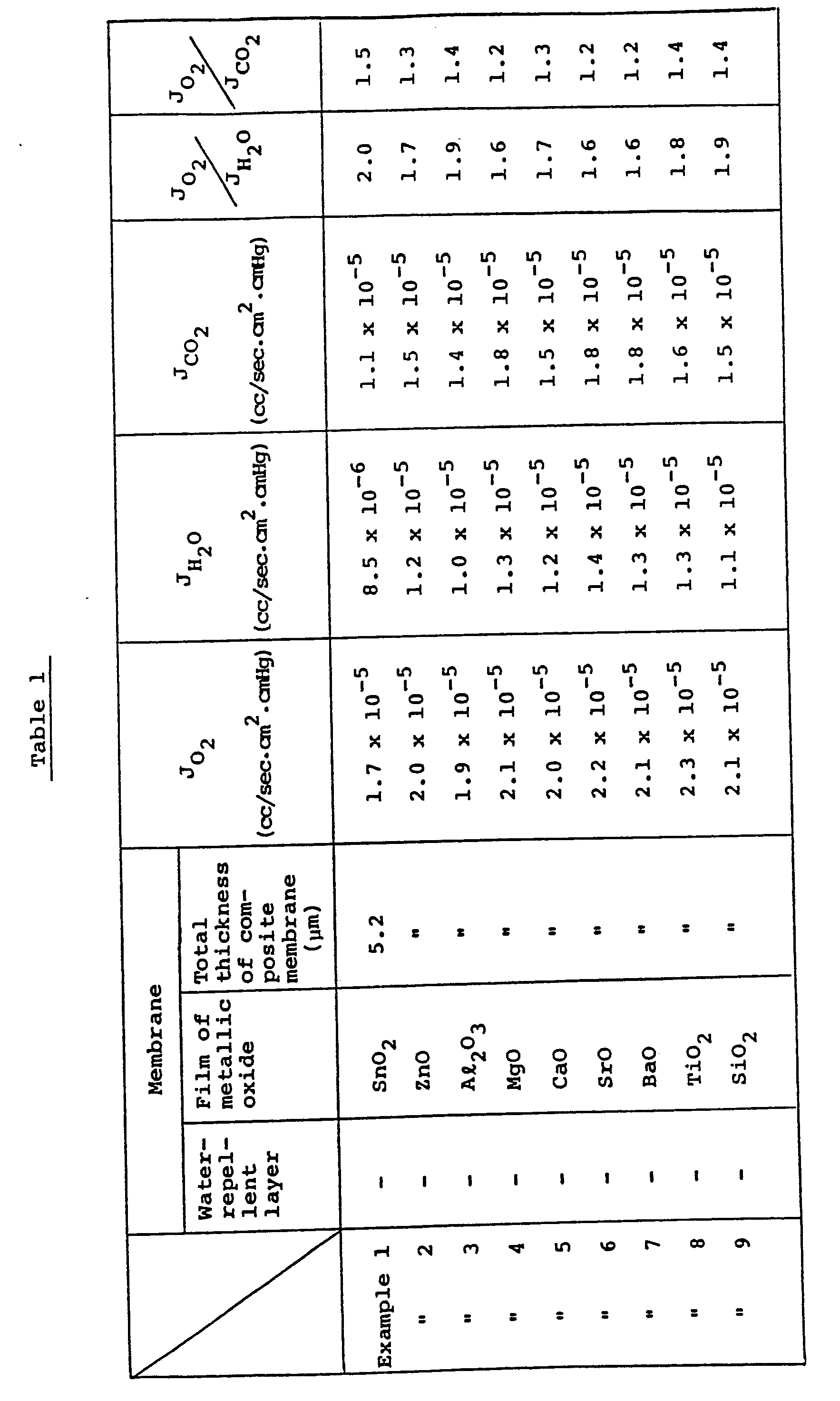
- Each porous polycarbonate membrane in which the fine pores having an average pore size of 0.03 µm are uniformly distributed and the pores of which have as much a space volume as 0.42% (Nuclepore (trade name) made of Nuclepore Corp. and having a thickness of 5 pm) was subjected to a sputtering treatment by use of Sn, Zn, Al, Mg, Ca, Sr, Ba, Ti or Si as a sputtering source in a mixed gas of argon and oxygen (consisting of 90% by volume of Ar and 10% by volume of 02) having a pressure of 0.27 Pa (2 x 10⁻³ Torr) and at a high-frequency power of 100 W, in order to deposit each film of various metallic oxides on either side of the polycarbonate membrane, with the thickness of the obtained film being 0.2 pm.
- Sputtering of fluoroethylene propylene (FEP) was carried out for the same type of polycarbonate membranes as in Examples 1 to 9 in an argon gas having a pressure of 1.3 Pa (1 x 10⁻² Torr) and at a high-frequency power of 200 W in order to deposit a water repellent layer of 0.2 um in thickness on either surface of each membrane. The same procedure as in Examples 1 to 9 was then repeated to further deposit each film having a thickness of 0.2 um of various metallic oxides on the water repellent layer already prepared on the polycarbonate membrane.
- The same type of polycarbonate membranes as in Examples 1 to 9 was placed in a plasma reaction tank, a high-frequency power of 13.56 MHz was applied to the tank from outside, an argon gas and a monomer gas of pentafluorostyrene were introduced into the tank at a flow rate of 600 ml/min, and a plasma polymerization reaction was then carried out therein under the condition of a radio-frequency output of 0.4 W/cm2 in order to deposit a 0.2-µm-thick layer of the pentafluorostyrene polymer on either surface of each polycarbonate membrane.
- Further, each film (0.2 pm) of various metallic oxides was then deposited on the already prepared layer in the same manner as in Examples 1 to 9.
- The thus obtained 27 kinds of composite membrane were measured for oxygen-permeation rates (JO2: cc/sec.cm2. cmHg) and carbon dioxide gas-permeation rates JCO2: cc/sec·cm2·cmHg) in accordance with an equable pressure method in which a gas chromatograph is employed as a detecting means, and for water vapor-permeation rates (JH2O: cc/sec·cm2·cmHg) in a manner corresponding to JIS Z 0208 (a cup method). Afterward, ratios (JO2/JH2O and JO2/JCO2) of JH2O and JCO2 to JO2 were calculated out, which ratios can be taken as gas permeation ratios.
- For comparison, the measurements of JO2' JH2O and JCO2 were similarly carried out for a polysiloxane membrane (Comparative Example 1) of 50 µm in thickness, an intermediate density polyethylene membrane of 20 µm in thickness (Comparative Example 2), a biaxially orientated polypropylene membrane (Comparative Example 3) of 20 pm in thickness, a polytetrafluoroethylene membrane (Comparative Example 4) of 20 µm in thickness, a commercially available FEP membrane (Comparative Example 5) of 20 µm in thickness, and an FEP membrane (Comparative Example 6) of 0.2 pm in thickness which was deposited by the same sputtering process as in Examples 10 to 18. And the ratios of JO2/JH2O and JO2/JCO2 were likewise calculated out.
- Obtained results are set forth all together in Table 1 below:


- There were used, as electrode bodies, Raney nickel plates (200 pm in thickness) where the average pore size of each plate was 5 pm and its porosity was 80%. Each plate was set on a vacuum depositing equipment, the temperature therein was maintained at 150°C, and the partial pressure of oxygen in the equipment was then adjusted to 0.67 Pa (5 x 10⁻³ Torr). As deposition sources, 9 metals of Sn, Zn, Al, Mg, Ca, Sr, Ba, Ti and Si were each selected.
- An ordinary deposition process has been employed to directly deposit each aforementioned metal on either surface of the Raney nickel plate. In every case, a metallic oxide of 0.2 pm in thickness was deposited on the surface of the Raney nickel.
- The thus obtained metallic oxide-deposited Raney nickels were dipped into a 2% palladium chloride solution and were subjected to cathodic polarization in order to deposit thereon a palladium layer having a thickness of about 0.5 pm inclusive of palladium in pores on the Raney nickel plate. The thus obtained products are air electrodes.
- The same manner as in Examples 28 to 36 was repeated except that the deposition process was replaced with a sputtering process. The sputtering treatment was carried out in a mixed gas of argon and oxygen (consisting of 90% by volume of Ar and 10% by volume of O2) at a pressure of 0.27 Pa (2 x 10⁻³ Torr) and under a high-frequency power of 100 W. Every film of the metallic oxide had a thickness of 0.2 µm.
- Porous polycarbonate membranes (Nuclepore (trade name) made by Nuclepore Corp.) in which pores of 0.03 µm in average diameter were uniformly distributed were each set on a vacuum depositing equipment and an ambient temperature was maintained at 100°C. The partial pressure of oxygen in the equipment was adjusted to a level of 0.67 Pa (5 x 10⁻³ Torr), and the same deposition sources as used in Examples 28 to 36 were applied in order to deposit each 0.2-pm-thick film of the metallic oxides on either surface of the membrane. Afterward, each porous membrane was compressedly bonded, on another surface thereof, to either surface of the Raney nickel plate (200 µm in thickness) having an average pore size of 5 µm and a porosity of 80%.
- The thus treated Raney nickel plates were each dipped into a 2% palladium chloride solution and were each subjected to cathodic polarization in order to deposit thereon a palladium layer having a thickness of about 0.5 pm inclusive of palladium in pores on the Raney nickel plate. The thus obtained products are air electrodes.
- The same manner as in Examples 46 to 54 was repeated except that the deposition process was replaced with the sputtering process under the same sputtering conditions as used in Examples 37 to 45 in order to prepare air electrodes.
- After active carbon powder was suspended in an aqueous palladium chloride solution, reduction treatment was carried out by the use of formalin in order to obtain the active carbon powder wearing palladium. Then, the obtained powder was subjected to a waterproof treatment with a 10 to 15% polytetrafluoroethylene dispersion, was mixed with a PTFE powder as a binding agent, and was then rolled to a sheet. The thus prepared sheet was compressedly bonded to a nickel net in order to obtain an electrode body of 0.6 mm in thickness. On the other hand, an artificial graphite powder was mixed with a PTFE dispersion, followed by a heat treatment to prepare a waterproof graphite powder. A PTFE powder which was a binding agent was mixed with this graphite powder, and the resultant mixture was then rolled to a sheet. The thus obtained sheet was compressedly bonded to the already obtained electrode body in order to prepare an air electrode of 1.6 mm in thickness.
- A polysiloxane membrane (50 pm in thickness) which was a membrane for allowing oxygen gas to selectively permeate therethrough was compressedly bonded to either surface of a Raney nickel plate (200 pm in thickness) having an average pore diameter of 5 µm and a porosity of 80%, and the whole membrane was subjected to cathodic polarization in a 2% palladium chloride solution in order to deposit thereon a palladium layer having a thickness of 0.5 pm inclusive of palladium in pores on the Raney nickel plate. The thus obtained product is the air electrode.
- A water vapor-absorbing layer comprising calcium chloride was deposited on the air-side surface of the air electrode prepared in Comparative Example 7.
- A thin layer of SnO2 having a thickness of 0.2 pm was deposited on one surface of a 5-µm-thick porous polycarbonate membrane (Nuclepore (trade name) made by Nuclepore Corp.) in which pores of 0.15 µm in average pore size were distributed, and another surface of the membrane above was compressedly bonded to either surface of a Raney nickel plate having an average pore diameter of 5 pm and a porosity of 80%. The whole plate was dipped into a 2% palladium chloride solution and was subjected to cathodic polarization in order to deposit thereon a palladium layer of about 0.5 pm in thickness inclusive of palladium in pores on the Raney nickel plate. The thus obtained product is an air electrode.
- The same manner as in Comparative Example 10 was repeated with the exception that there was employed a porous polycarbonate membrane having an average pore size of 0.03 µm and was deposited a film of SnO2 having a thickness of 0.005 pm in order to prepare a desired air electrode.
- The procedure described in Example 11 was repeated except that a film of Sn02 having a thickness of 2.0 pm was deposited in order to prepare an air electrode.
- Next, an air-zinc cell was assembled by the use of each of 42 air electrodes thus prepared above, an opposite electrode of a geled zinc which was amalgamated with 3% by weight of mercury, an electrolyte of potassium hydroxide, and a separator of a polyamide non-woven fabric material.
- These assembled 42 cells were then allowed to stand in air at 25°C for 16 hours. Afterward, measurement was carried out for the current density of each cell at the time when a terminal voltage dropped below 1.0 V after 5 minutes' discharge under a variety of currents. Further, each cell was stored in an atmosphere at 45°C and at a relative humidity of 90%, and the leakage state of a used electrolyte was observed.
- Moreover, the same discharge test as mentioned above was carried out for each cell which had undergone the above storage step, and the proportion (%) of a current value at this test time to an initial current value was calculated out. The thus calculated values each represent a degradatiion level of the air electrode in the cell and can be taken as a maintenance proportion of its discharge properties. In other words, it can be meant that the greater this value, the smaller the deterioration in the air electrode is.
- Further, the film deposited on each electrode was measured for a permeability rate to oxygen gas in accordance with an equable pressure method in which a gas chromatograph is employed as a detecting means, and for a permeability rate to water-vapor in a manner corresponding to JIS Z 0208 (a cup method). Afterward, ratios of both the rates were calculated out.
- The obtained results are set forth in Table 2 below:


- There were used, as electrode bodies, Raney nickel plates (200 pm in thickness) where the average pore size of each plate was 5 pm and its porosity was 80%. Sputtering of fluoroethylene propylene (FEP) was carried out for the one side of the Raney nickel plate in an argon gas having a pressure of 1.3 Pa (1 x 10⁻² Torr) and at a high-frequency power of 200 W in order to deposit a water repellent layer of 0.2 µm in thickness on either surface of each membrane.
- After each plate was set on a vacuum depositing equipment, the temperature of the side of FEP water repellent layer was maintained at 100°C, and the partial pressure of oxygen in the equipment was adjusted to 0.67 Pa (5 x 10⁻³ Torr). As deposition sources, 9 metals of Sn, Zn, Al, Mg, Ca, Sr, Ba, Ti and Si were each selected. An ordinary deposition process has been employed to directly deposit each aforementioned metal on either surface of the FEP water repellent layer. In every case, a metallic oxide of 0.2 pm in thickness was deposited on the surface of the FEP water repellent layer.
- The thus obtained metallic oxide-deposited plates were dipped into a 2% palladium chloride solution and were subjected to cathodic polarization in order to deposit thereon a palladium layer having a thickness of about 0.5 pm inclusive of palladium in pores on the Raney nickel plate. The thus obtained products are air electrodes.
- The same manner as in Examples 64 to 72 was repeated except that the deposition process was replaced with a sputtering process when the metallic thin layer was formed on the surface of the FEP water repellent layer. The sputtering treatment was carried out in a mixed gas of argon and oxygen (consisting of 90% by volume of Ar and 10% by volume of 02) at a pressure of 0.27 Pa (2 x 10⁻³ Torr) and under a high-frequency power of 100 W. Every film of the metallic oxide had a thickness of 0.1 pm.
- To one side of porous polycarbonate membrane (Nuclepore (trade name) made by Nuclepore Corp.) in which pores of 0.03 pm in average diameter were uniformly distributed, sputtering of fluoroethylene propylene (FEP) was carried out in an argon gas having a pressure of 1.3 Pa (1 x 10⁻² Torr) and at a high-frequency power of 200 W in order to deposit a water repellent layer of 0.2 µm in thickness on either surface of each membrane.
- After each plate was set on a vacuum depositing equipment, the temperature of the water repellent layer was maintained at 100°C. And the partial pressure of oxygen in the equipment was adjusted to 0.67 Pa (5 x 10⁻³ Torr) in order to form a thin layer of metallic oxide on the surface of the water repellent layer using the same deposition source as in Examples 64 to 72. In every case, a thin layer of 0.1 pm in thickness was deposited on the surface of the FEP water repellent layer.
- The thus obtained porous polycarbonate membrane of the composite thin membrane was compressedly bonded to either surface of the Raney nickel plate (200 pm in thickness) having an average pore size of 5 µm and a porosity of 80%.
- The thus obtained metallic oxide-deposited plates were dipped into a 2% palladium chloride solution and were subjected to cathodic polarization in order to deposit thereon a palladium layer having a thickness of about 0.5 µm inclusive of palladium in pores on the Raney nickel plate. The thus obtained products are air electrodes.
- The same manner as in Examples 82 to 90 was repeated except that the deposition process was replaced with a sputtering process when the metallic thin layer was formed on the surface of the FEP water repellent layer. In this case, the sputtering treatment was carried out in a mixed gas of argon and oxygen (consisting of 90% by volume of Ar and 10% by volume of 02) at a pressure of 0.27 Pa (2 x 10⁻³ Torr) and under a high-frequency power of 100 W. Every thin layer of the metallic oxide had a thickness of 0.1 um.
- These assembled 36 cells were then allowed to stand in air at 25°C for 16 hours. Afterward, measurement was carried out for the current density, the maintenance proportion of their discharge properties and the gas permeation ratio of the film of each cell as the same procedures in Examples 28 to 63.
- The obtained results are set forth in Table 3 below:


- The performance assessment of the air electrodes in Examples above was determined using potassium hydroxide as an electrolyte. However, it is definite that similar effects can also be obtained, needless to say, by use of another electrolyte, for example, ammonium chloride, sodium hydroxide, or an electrolyte which is added rubidium hydroxide, lithium hydroxide, cesium hydroxide or the like to the aforementioned electrolyte. Additionally, it has been found that the air-electrode in which the composite membrane with respect to this invention is employed can be applied in an air-iron cell.
- As be apparent from the above description, the oxygen gas permselective membrane according to this invention, though being very thin, does not allow water vapor and carbon dioxide gas in air to permeate therethrough and has a great function for allowing oxygen gas to selectively permeate therethrough. Therefore, the air electrode comprising a combination of this oxygen gas permselective membrane and the electrode body may be designed overall in a thin form and enables a heavy-load discharge for a long period of time. It is noteworthy that such an air electrode also improves in storage properties and leakage resistance.
- Therefore, it can be estimated that the oxygen gas permselective membrane according to this invention is industrially highly valuable and beneficial.
- Further, the air electrode in which the aforementioned oxygen gas permselective membrane is employed may be designed overall in a thin structure and does not allow water vapor or carbon dioxide gas in air to permeate the electrode body. Therefore, such an electrode can be utilized for a prolonged heavy-load discharge and is excellent in storage properties. It can thus be concluded that such an air electrode is industrially valuable and beneficial.
Claims (11)
Applications Claiming Priority (4)
| Application Number | Priority Date | Filing Date | Title |
|---|---|---|---|
| JP107631/82 | 1982-06-24 | ||
| JP57107631A JPS58225570A (en) | 1982-06-24 | 1982-06-24 | Air electrode and its production method |
| JP156758/82 | 1982-09-10 | ||
| JP57156758A JPS5946102A (en) | 1982-09-10 | 1982-09-10 | Composite membrane selectively permeable for gaseous oxygen |
Publications (3)
| Publication Number | Publication Date |
|---|---|
| EP0097770A2 EP0097770A2 (en) | 1984-01-11 |
| EP0097770A3 EP0097770A3 (en) | 1986-11-26 |
| EP0097770B1 true EP0097770B1 (en) | 1990-05-16 |
Family
ID=26447653
Family Applications (1)
| Application Number | Title | Priority Date | Filing Date |
|---|---|---|---|
| EP83102715A Expired - Lifetime EP0097770B1 (en) | 1982-06-24 | 1983-03-18 | Oxygen gas permselective membrane |
Country Status (4)
| Country | Link |
|---|---|
| US (1) | US4483694A (en) |
| EP (1) | EP0097770B1 (en) |
| CA (1) | CA1194925A (en) |
| DE (1) | DE3381577D1 (en) |
Families Citing this family (29)
| Publication number | Priority date | Publication date | Assignee | Title |
|---|---|---|---|---|
| US5127925A (en) * | 1982-12-13 | 1992-07-07 | Allied-Signal Inc. | Separation of gases by means of mixed matrix membranes |
| DE3332566A1 (en) * | 1983-09-09 | 1985-03-28 | Hoechst Ag, 6230 Frankfurt | GAS DIFFUSION ELECTRODE WITH HYDROPHILIC TOP LAYER AND METHOD FOR THEIR PRODUCTION |
| DE3573493D1 (en) * | 1984-02-24 | 1989-11-09 | Toshiba Kk | Oxygen permeable membrane |
| US4708917A (en) * | 1985-12-23 | 1987-11-24 | International Fuel Cells Corporation | Molten carbonate cathodes and method of fabricating |
| US6488739B1 (en) | 1987-03-13 | 2002-12-03 | Bp Corporation North America Inc. | Oxygen production process |
| US5591315A (en) * | 1987-03-13 | 1997-01-07 | The Standard Oil Company | Solid-component membranes electrochemical reactor components electrochemical reactors use of membranes reactor components and reactor for oxidation reactions |
| US4915988A (en) * | 1988-06-22 | 1990-04-10 | Georgia Tech Research Corporation | Chemical vapor deposition of group IIA metals and precursors therefor |
| CA2017243C (en) * | 1989-05-25 | 2003-09-30 | Terry J. Mazanec | Novel solid multi-component membranes, electrochemical reactor and use of membranes and reactor for oxidation reactions |
| US5045828A (en) * | 1989-07-27 | 1991-09-03 | Texas Instruments Incorporated | Fluoropolymer humidity sensors |
| US5342431A (en) * | 1989-10-23 | 1994-08-30 | Wisconsin Alumni Research Foundation | Metal oxide membranes for gas separation |
| US5254143A (en) * | 1990-07-09 | 1993-10-19 | Dainippon Ink And Chemical, Inc. | Diaphragm for gas-liquid contact, gas-liquid contact apparatus and process for producing liquid containing gas dissolved therein |
| US5453298A (en) * | 1990-11-08 | 1995-09-26 | California Institute Of Technology | Method for forming H2-permselective oxide membranes |
| DE4117284A1 (en) * | 1991-05-27 | 1992-12-03 | Studiengesellschaft Kohle Mbh | METHOD FOR PRODUCING MICROPOROUS CERAMIC MEMBRANES FOR THE SEPARATION OF GAS AND LIQUID MIXTURES |
| US5443743A (en) * | 1991-09-11 | 1995-08-22 | Pall Corporation | Gas plasma treated porous medium and method of separation using same |
| NL9300038A (en) * | 1993-01-08 | 1994-08-01 | Hoogovens Ind Ceramics | Ceramic ultrafiltration membrane and process for its preparation. |
| US5451386A (en) * | 1993-05-19 | 1995-09-19 | The State Of Oregon Acting By And Through The State Board Of Higher Education On Behalf Of Osu | Hydrogen-selective membrane |
| US5487774A (en) * | 1993-11-08 | 1996-01-30 | Wisconsin Alumni Research Foundation | Gas phase fractionation method using porous ceramic membrane |
| US5439624A (en) * | 1994-02-14 | 1995-08-08 | Wisconsin Alumni Research Foundation | Method for forming porous ceramic materials |
| AU706663B2 (en) * | 1994-09-23 | 1999-06-17 | Standard Oil Company, The | Oxygen permeable mixed conductor membranes |
| US6676935B2 (en) | 1995-06-27 | 2004-01-13 | Cell Genesys, Inc. | Tissue specific adenoviral vectors |
| US5807642A (en) * | 1995-11-20 | 1998-09-15 | Xue; Liang An | Solid oxide fuel cell stacks with barium and strontium ceramic bodies |
| US5766784A (en) * | 1996-04-08 | 1998-06-16 | Battelle Memorial Institute | Thin films and uses |
| US5985475A (en) * | 1997-06-17 | 1999-11-16 | Aer Energy Resources, Inc. | Membrane for selective transport of oxygen over water vapor and metal-air electrochemical cell including said membrane |
| US6432586B1 (en) | 2000-04-10 | 2002-08-13 | Celgard Inc. | Separator for a high energy rechargeable lithium battery |
| US6432177B1 (en) * | 2000-09-12 | 2002-08-13 | Donaldson Company, Inc. | Air filter assembly for low temperature catalytic processes |
| WO2004055930A2 (en) * | 2002-12-02 | 2004-07-01 | Donaldson Company, Inc. | Various filter elements for hydrogen fuel cell |
| US20050202306A1 (en) * | 2004-03-11 | 2005-09-15 | Celgard Inc. | Direct methanol fuel cell |
| DE102006024022B4 (en) * | 2006-05-23 | 2008-05-08 | It Dr. Gambert Gmbh | Lead-free galvanic oxygen sensor |
| CN116288943B (en) * | 2023-03-17 | 2024-08-20 | 嘉兴南湖学院 | Preparation method of double-function film capable of optimizing cathode of metal-air battery |
Family Cites Families (16)
| Publication number | Priority date | Publication date | Assignee | Title |
|---|---|---|---|---|
| FR1255382A (en) * | 1960-01-23 | 1961-03-10 | Commissariat Energie Atomique | Improvements to methods and devices for coating a macroporous metal support with a microporous metal layer |
| GB1113273A (en) * | 1964-05-16 | 1968-05-08 | Kinzoku Zairyo Kenkyusho | A dispersion type metallic oxide silver alloy membrane for use in a device for separating and purifying oxygen |
| US3359705A (en) * | 1966-10-27 | 1967-12-26 | Union Carbide Corp | Oxygen permeable membranes |
| US4054725A (en) * | 1969-03-10 | 1977-10-18 | Hitachi Maxell, Ltd. | Cell utilizing atmospheric oxygen as depolarizer |
| US3692087A (en) * | 1969-03-17 | 1972-09-19 | Norton Co | Metallic porous plates |
| GB1272095A (en) * | 1969-03-21 | 1972-04-26 | Energy Conversion Ltd | Improvements in and relating to electrochemical cells |
| JPS4826896A (en) * | 1971-08-11 | 1973-04-09 | ||
| IT1002909B (en) * | 1973-02-17 | 1976-05-20 | Deutsche Automobilgesellsch | MEMBRANE FOR THE SEPARATION OF HYDRO GENO FROM MIXTURES OF GAS CONTAINING HYDROGEN |
| US3864418A (en) * | 1973-03-12 | 1975-02-04 | Standard Oil Co | Process of separating complexable materials employing semipermeable polymer film |
| JPS5334077B2 (en) * | 1973-08-29 | 1978-09-19 | ||
| FR2366217A1 (en) * | 1975-08-27 | 1978-04-28 | Comp Generale Electricite | HYDROGEN GENERATOR DEVICE |
| US4105830A (en) * | 1977-08-01 | 1978-08-08 | Union Carbide Corporation | Air depolarized cell |
| US4214020A (en) * | 1977-11-17 | 1980-07-22 | Monsanto Company | Processes for coating bundles of hollow fiber membranes |
| US4189526A (en) * | 1978-05-05 | 1980-02-19 | Gould Inc. | Metal/oxygen cells and method for optimizing the active life properties thereof |
| US4175153A (en) * | 1978-05-16 | 1979-11-20 | Monsanto Company | Inorganic anisotropic hollow fibers |
| US4268278A (en) * | 1978-05-16 | 1981-05-19 | Monsanto Company | Inorganic anisotropic hollow fibers |
-
1983
- 1983-03-14 US US06/475,687 patent/US4483694A/en not_active Expired - Fee Related
- 1983-03-14 CA CA000423565A patent/CA1194925A/en not_active Expired
- 1983-03-18 DE DE8383102715T patent/DE3381577D1/en not_active Expired - Lifetime
- 1983-03-18 EP EP83102715A patent/EP0097770B1/en not_active Expired - Lifetime
Also Published As
| Publication number | Publication date |
|---|---|
| CA1194925A (en) | 1985-10-08 |
| DE3381577D1 (en) | 1990-06-21 |
| EP0097770A3 (en) | 1986-11-26 |
| EP0097770A2 (en) | 1984-01-11 |
| US4483694A (en) | 1984-11-20 |
Similar Documents
| Publication | Publication Date | Title |
|---|---|---|
| EP0097770B1 (en) | Oxygen gas permselective membrane | |
| EP0154468B1 (en) | Oxygen permeable membrane | |
| CA1118038A (en) | Metal/oxygen cells and method for optimizing the active life properties thereof | |
| EP0337036B1 (en) | A method for bonding a conductive layer on an electrode structure | |
| CA2482488C (en) | Composite films for electrochemical devices | |
| JPS5955314A (en) | Manufacture of composite permselective membrane for gaseous oxygen | |
| JP7774400B2 (en) | Zinc secondary battery | |
| JPS5854564A (en) | Porous catalyst layer for gas diffusion electrode | |
| JPS58225575A (en) | Air electrode and its production method | |
| JPS6044003A (en) | Oxygen gas permselective composite membrane and air electrode comprising the same | |
| JPS6051505A (en) | Gas selective composite membrane | |
| JPS58225573A (en) | Air electrode and its production method | |
| JPS5955315A (en) | Manufacture of composite film having selective oxygen permeability | |
| US4318967A (en) | Long-life galvanic primary cell | |
| JPS60180063A (en) | Air electrode | |
| JPS58225570A (en) | Air electrode and its production method | |
| JPS58225572A (en) | Air electrode and its production method | |
| JPS5998706A (en) | Oxygen gas permselective composite membrane | |
| JPS60220555A (en) | electrochemical cell | |
| JPS60133675A (en) | Air electrode | |
| JPS5994377A (en) | Manufacture of air electrode | |
| JPS60179112A (en) | Compound film having permselectivity for oxygen | |
| JPS5954175A (en) | Manufacture of air electrode | |
| JPS5958759A (en) | Air electrode and its manufacture | |
| JPS5946104A (en) | Composite membrane selectively permeable for gaseous oxygen |
Legal Events
| Date | Code | Title | Description |
|---|---|---|---|
| PUAI | Public reference made under article 153(3) epc to a published international application that has entered the european phase |
Free format text: ORIGINAL CODE: 0009012 |
|
| AK | Designated contracting states |
Designated state(s): CH DE FR GB LI SE |
|
| RAP1 | Party data changed (applicant data changed or rights of an application transferred) |
Owner name: KABUSHIKI KAISHA TOSHIBA |
|
| PUAL | Search report despatched |
Free format text: ORIGINAL CODE: 0009013 |
|
| AK | Designated contracting states |
Kind code of ref document: A3 Designated state(s): CH DE FR GB LI SE |
|
| 17P | Request for examination filed |
Effective date: 19870422 |
|
| 17Q | First examination report despatched |
Effective date: 19880302 |
|
| GRAA | (expected) grant |
Free format text: ORIGINAL CODE: 0009210 |
|
| AK | Designated contracting states |
Kind code of ref document: B1 Designated state(s): CH DE FR GB LI SE |
|
| PG25 | Lapsed in a contracting state [announced via postgrant information from national office to epo] |
Ref country code: SE Effective date: 19900516 Ref country code: LI Effective date: 19900516 Ref country code: CH Effective date: 19900516 |
|
| ET | Fr: translation filed | ||
| REF | Corresponds to: |
Ref document number: 3381577 Country of ref document: DE Date of ref document: 19900621 |
|
| REG | Reference to a national code |
Ref country code: CH Ref legal event code: PL |
|
| PLBE | No opposition filed within time limit |
Free format text: ORIGINAL CODE: 0009261 |
|
| STAA | Information on the status of an ep patent application or granted ep patent |
Free format text: STATUS: NO OPPOSITION FILED WITHIN TIME LIMIT |
|
| PGFP | Annual fee paid to national office [announced via postgrant information from national office to epo] |
Ref country code: SE Payment date: 19910320 Year of fee payment: 9 |
|
| 26N | No opposition filed | ||
| PGFP | Annual fee paid to national office [announced via postgrant information from national office to epo] |
Ref country code: GB Payment date: 19950308 Year of fee payment: 13 |
|
| PGFP | Annual fee paid to national office [announced via postgrant information from national office to epo] |
Ref country code: FR Payment date: 19950309 Year of fee payment: 13 Ref country code: DE Payment date: 19950309 Year of fee payment: 13 |
|
| PG25 | Lapsed in a contracting state [announced via postgrant information from national office to epo] |
Ref country code: GB Effective date: 19960318 |
|
| GBPC | Gb: european patent ceased through non-payment of renewal fee |
Effective date: 19960318 |
|
| PG25 | Lapsed in a contracting state [announced via postgrant information from national office to epo] |
Ref country code: FR Effective date: 19961129 |
|
| PG25 | Lapsed in a contracting state [announced via postgrant information from national office to epo] |
Ref country code: DE Effective date: 19961203 |
|
| REG | Reference to a national code |
Ref country code: FR Ref legal event code: ST |