EP0097300B1 - Keramische Szintillatoren aus seltenen Erden - Google Patents
Keramische Szintillatoren aus seltenen Erden Download PDFInfo
- Publication number
- EP0097300B1 EP0097300B1 EP83105770A EP83105770A EP0097300B1 EP 0097300 B1 EP0097300 B1 EP 0097300B1 EP 83105770 A EP83105770 A EP 83105770A EP 83105770 A EP83105770 A EP 83105770A EP 0097300 B1 EP0097300 B1 EP 0097300B1
- Authority
- EP
- European Patent Office
- Prior art keywords
- radiation
- rare
- scintillator
- earth
- detector
- Prior art date
- Legal status (The legal status is an assumption and is not a legal conclusion. Google has not performed a legal analysis and makes no representation as to the accuracy of the status listed.)
- Expired
Links
Images
Classifications
-
- C—CHEMISTRY; METALLURGY
- C04—CEMENTS; CONCRETE; ARTIFICIAL STONE; CERAMICS; REFRACTORIES
- C04B—LIME, MAGNESIA; SLAG; CEMENTS; COMPOSITIONS THEREOF, e.g. MORTARS, CONCRETE OR LIKE BUILDING MATERIALS; ARTIFICIAL STONE; CERAMICS; REFRACTORIES; TREATMENT OF NATURAL STONE
- C04B35/00—Shaped ceramic products characterised by their composition; Ceramics compositions; Processing powders of inorganic compounds preparatory to the manufacturing of ceramic products
- C04B35/50—Shaped ceramic products characterised by their composition; Ceramics compositions; Processing powders of inorganic compounds preparatory to the manufacturing of ceramic products based on rare-earth compounds
-
- C—CHEMISTRY; METALLURGY
- C04—CEMENTS; CONCRETE; ARTIFICIAL STONE; CERAMICS; REFRACTORIES
- C04B—LIME, MAGNESIA; SLAG; CEMENTS; COMPOSITIONS THEREOF, e.g. MORTARS, CONCRETE OR LIKE BUILDING MATERIALS; ARTIFICIAL STONE; CERAMICS; REFRACTORIES; TREATMENT OF NATURAL STONE
- C04B35/00—Shaped ceramic products characterised by their composition; Ceramics compositions; Processing powders of inorganic compounds preparatory to the manufacturing of ceramic products
- C04B35/622—Forming processes; Processing powders of inorganic compounds preparatory to the manufacturing of ceramic products
- C04B35/64—Burning or sintering processes
- C04B35/645—Pressure sintering
-
- C—CHEMISTRY; METALLURGY
- C09—DYES; PAINTS; POLISHES; NATURAL RESINS; ADHESIVES; COMPOSITIONS NOT OTHERWISE PROVIDED FOR; APPLICATIONS OF MATERIALS NOT OTHERWISE PROVIDED FOR
- C09K—MATERIALS FOR MISCELLANEOUS APPLICATIONS, NOT PROVIDED FOR ELSEWHERE
- C09K11/00—Luminescent, e.g. electroluminescent, chemiluminescent materials
- C09K11/08—Luminescent, e.g. electroluminescent, chemiluminescent materials containing inorganic luminescent materials
- C09K11/77—Luminescent, e.g. electroluminescent, chemiluminescent materials containing inorganic luminescent materials containing rare earth metals
- C09K11/7783—Luminescent, e.g. electroluminescent, chemiluminescent materials containing inorganic luminescent materials containing rare earth metals containing two or more rare earth metals one of which being europium
- C09K11/7784—Chalcogenides
- C09K11/7787—Oxides
-
- G—PHYSICS
- G01—MEASURING; TESTING
- G01T—MEASUREMENT OF NUCLEAR OR X-RADIATION
- G01T1/00—Measuring X-radiation, gamma radiation, corpuscular radiation, or cosmic radiation
- G01T1/16—Measuring radiation intensity
- G01T1/20—Measuring radiation intensity with scintillation detectors
- G01T1/202—Measuring radiation intensity with scintillation detectors the detector being a crystal
- G01T1/2023—Selection of materials
-
- C—CHEMISTRY; METALLURGY
- C04—CEMENTS; CONCRETE; ARTIFICIAL STONE; CERAMICS; REFRACTORIES
- C04B—LIME, MAGNESIA; SLAG; CEMENTS; COMPOSITIONS THEREOF, e.g. MORTARS, CONCRETE OR LIKE BUILDING MATERIALS; ARTIFICIAL STONE; CERAMICS; REFRACTORIES; TREATMENT OF NATURAL STONE
- C04B2235/00—Aspects relating to ceramic starting mixtures or sintered ceramic products
- C04B2235/02—Composition of constituents of the starting material or of secondary phases of the final product
- C04B2235/30—Constituents and secondary phases not being of a fibrous nature
- C04B2235/32—Metal oxides, mixed metal oxides, or oxide-forming salts thereof, e.g. carbonates, nitrates, (oxy)hydroxides, chlorides
- C04B2235/3224—Rare earth oxide or oxide forming salts thereof, e.g. scandium oxide
- C04B2235/3225—Yttrium oxide or oxide-forming salts thereof
-
- C—CHEMISTRY; METALLURGY
- C04—CEMENTS; CONCRETE; ARTIFICIAL STONE; CERAMICS; REFRACTORIES
- C04B—LIME, MAGNESIA; SLAG; CEMENTS; COMPOSITIONS THEREOF, e.g. MORTARS, CONCRETE OR LIKE BUILDING MATERIALS; ARTIFICIAL STONE; CERAMICS; REFRACTORIES; TREATMENT OF NATURAL STONE
- C04B2235/00—Aspects relating to ceramic starting mixtures or sintered ceramic products
- C04B2235/65—Aspects relating to heat treatments of ceramic bodies such as green ceramics or pre-sintered ceramics, e.g. burning, sintering or melting processes
- C04B2235/658—Atmosphere during thermal treatment
- C04B2235/6581—Total pressure below 1 atmosphere, e.g. vacuum
-
- C—CHEMISTRY; METALLURGY
- C04—CEMENTS; CONCRETE; ARTIFICIAL STONE; CERAMICS; REFRACTORIES
- C04B—LIME, MAGNESIA; SLAG; CEMENTS; COMPOSITIONS THEREOF, e.g. MORTARS, CONCRETE OR LIKE BUILDING MATERIALS; ARTIFICIAL STONE; CERAMICS; REFRACTORIES; TREATMENT OF NATURAL STONE
- C04B2235/00—Aspects relating to ceramic starting mixtures or sintered ceramic products
- C04B2235/70—Aspects relating to sintered or melt-casted ceramic products
- C04B2235/74—Physical characteristics
- C04B2235/76—Crystal structural characteristics, e.g. symmetry
- C04B2235/762—Cubic symmetry, e.g. beta-SiC
Definitions
- This invention relates to X-ray detectors and more particularly to the class of X-ray detectors which have come to be known as solid state.
- Detectors of this sort have an important use in CT scanners, although it is expected that they will also find use in fields of gamma and nuclear radiation detection, as well as in the developing field of computed radiography.
- Scintillators or scintillation detectors have long been in use as detectors of penetrating radiation, such uses including counting applications and imaging applications.
- counting applications the paramount requirement is to produce a sharp pulse of radiation in response to receipt of a high energy photon, such that a coupled photomultiplier can produce a sharp pulse for counting.
- Imaging applications such as image intensifiers can be characterized as qualitative (analog) rather than quantitative (digital) imaging systems such that resolution is an important characteristic, but detection accuracies of a few percent are satisfactory, and afterglow and hysteresis are not serious problems.
- computed tomography is the first truly quantitative commercial imaging technique. As such, it requires detection accuracies on the order of one part in one thousand for successive measurements taken at a relatively high rate.
- CT detector channels produce signals which are linear and are subsequently integrated by electronics to produce an electrical signal which is related to the incident radiation.
- CT detectors in this letter category are described and claimed in the following U.S. patents: 4,031,396; 4,119,853 and 4,161,655. That type of detector uses xenon gas under high pressure and operates on the principle of detecting X-rays by their proportional ionization of the xenon gas. The ionisation charge in the xenon gas is collected in an electric field established by spaced parallel tungsten plates and the charge collected is proportional to the number of X-rays absorbed in the gas.
- single crystals tend to be susceptible to the propagation of lattice defects along the crystal planes leading to increased afterglow and hysteresis as well as to unwanted cleaving and breaking of bars during lapping and polishing of scintillator bars.
- BGO suffers from too low a radiant efficiency (only 1.2%) and is relatively expensive.
- Csl:Tl has a serious problem with hysteresis. That is to say, its light output depends upon its irradiation history and varies from one bar to another. This makes accurate reconstruction of the image very difficult. Further problems with CsI:TI relate to its high thermal expansion coefficient and low mechanical strength. If the components inside a CT detector cell expand differentially by only a few tens of parts per million, the resulting mechanical deformations can cause artifacts in the image. Additionally, Csl:Tl is hygroscopic, toxic and expensive in the ultra-high purity required to reduce hysteresis and obtain low afterglow.
- CdW0 4 has problems.
- CdW0 4 like BGO and other unactivated scintillators, has a low (2.5-3.0%) radiant efficiency. This allows the signal output and noise to become comparable to the electronic noise, resulting in a degraded signal.
- CdW0 4 has a tendency to cleave apart like mica when it is cut, making it very difficult to obtain undamaged bars.
- CdW0 4 is expensive and difficult to obtain commercially, largely due to its high toxicity.
- FR-A-2 435 123 describes a detector consisting of a detector array having a plurality of channels, which channels include a scintillator and a photo-sensitive detector.
- the scintillator is comprised of BaFCI:Eu.
- An object according to the present invention is to provide a scintillator which has high X-ray stopping power, and at the same time high radiant efficiency and good transparency. Further in that regard, it is an object to provide such a scintillator with afterglow and hysteresis characteristics compatible with high resolution fast CT scanning.
- rare-earth compounds can be configured in a manner to be described in detail below to provide characteristics which are very compatible with CT requirements. Since most of the rare-earth compounds have very high X-ray stopping power, the crystals need not have extreme thicknesses in order to effectively stop the incident radiation. Many of the rare-earth compounds, when processed in the manner to be described, produce cubic crystal structures which are optically isotropic, that is, they exhibit the same refractive index in all directions. As a result, the emitted light will not refract at the crystal grain boundaries, and transparency and light output are enhanced.
- rare-earth oxide scintillators can be achieved while avoiding the difficulties associated with the monocrystalline approach to produce a scintillator having characteristics compatible wit modern CT requirements. More particularly, rare-earth oxides doped with rare-earth activators can be processed as described below to produce a polycrystalline ceramic scintillator having characteristics very compatible with modern CT or other digital imaging requirements.
- Our invention concerns a detector array (14) for a radiation detector for detection of penetrating radiation in a quantitative modality, said radiation detector being used with a source of penetrating radiation (10) and having a plurality of channels for receiving the radiation, the channels each including a scintillator (26) and a photo-resistive means (24) coupled thereto for producing a set of signals related to the radiation detected in the respective channels, characterized in that each scintillator (26) comprises a polycrystalline ceramic scintillator crystal for detecting the radiation in the channels, the crystals having a cubic crystal structure and a porosity no greater than about 0.1 % and being formed of at least one rare-earth oxide selected from the group consisting of Gd 2 0 3 , Y 2 0 3 , La 2 0 3 and Lu 2 0 3 , and doped with at least one rare-earth activator.
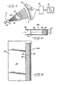
- Figure 1 shows the elements of a CT scanner involved in the production, transmission and detection of X radiation.
- the scanner includes a source of penetrating radiation 10, very often in the form of a rotating anode X-ray tube.
- the radiation produced by the X-ray tube 10 is collimated at 11 to produce a thin fan beam of radiation 12 which is projected through a patient aperture 13 toward an X-ray detector array 14.
- a body to be examined, such as a patient 15 is positioned within the patient aperture 13 in the path of the fan beam of X-rays 12 such that the beam passing through the body is attenuated in dependence on the density of the objects encountered.
- each detector cell 14a, 14b, etc. produces an electrical signal which is dependent on the intensity of the radiation received within the cell.
- the signals thus produced are therefore measures of the attenuation of the X-ray beam by the portion of the body through which it passed.
- readings are taken from each cell at a plurality of angular positions with respect to the patient, as the source and detector array are rotated about the patient aperture.
- the readings thus produced are digitized and fed to a reconstruction computer 16 which can use one of a number of available algorithms to compute the picture of the cross section traversed by the fan beam.
- the picture is displayed on a CRT 17, or alternatively can be used to create a film or the like for further study by a diagnostician.
- Figure 1 shows a scanner geometry which has come to be known as rotate-rotate, in which the source is fixed with respect to the detector array, and they rotate in unison around the patient aperture.
- Detector cells constructed in accordance with this invention are highly desirable for such an array because it requires very close cell spacing (at least at the central cells) in order to achieve the high spatial resolution of which it is capable.
- the detector cells taught herein are also useful for other types of CT scanner geometries, including the rotate only geometry using a fixed detector ring.
- FIG. 2 and 3 there is shown the configuration of a single cell 14a of the detector array 14.
- the cell width is defined by a pair of collimator plates 20, 21 which define a window 22 for receiving X-rays along an incremental portion of the fan beam 12 which it faces.
- a comparison of Figures 2 and 3 will show that the cell length (that is, the dimension perpendicular to the plane of the fan) is considerably greater than the cell width. It is important to minimize the cell width in order to get good spatial resolution (i.e., break the fan into as many channels as possible). Typical dimensions in a practical array can be about 2 mm. for the cell width, while the scintillator can be approximately 20 mm. in length, approximately 15 mm. of which is exposed to radiation.
- a photodiode assembly 24 is mounted behind the scintillator 26 and has an active surface 25 underlying the scintillator 26 and adapted to receive the radiation which it produces.
- the faces of the scintillator can be treated to reflect inwardly.
- optical coupling material can be applied between the diode and associated scintillator face to enhance coupling of the scintillator to the diode.
- a class of scintillator elements having superior light transmittance, having good conversion efficiency, and adapted to produce light at a wavelength compatible with available photodiodes.
- This class of scintillators is of further benefit because they are not monocrystalline as in the case of the scintillators typically used heretofore, but are polycrystalline ceramics having superior physical properties, and are thus more easily adapted to the physical requirements of long and reliable life in a CT scanner.
- the scintillator base material is a rare-earth oxide. Such materials are available in sufficiently pure form at reasonable expense and can be processed as described below to produce several desirable properties.
- the scintillator is produced by sintering or hot pressing techniques to form a polycrystalline ceramic. As a result, the manufacturing process is not overly expensive, and the resultant product is easily cut, polished, machined or the like to produce scintillator bars of the desired size.
- the polycrystalline ceramic can be formed by a process which yields a ceramic having a porosity no greater than about 0.1%. As a result, the material is very dense and has a very high X-ray stopping power.
- polycrystalline ceramics which are only about 2 mm in depth can produce equivalent stopping power to conventionally used monocrystalline Nal:Tl, of about 3 mm depth.
- crystals can be produced which are of only half the volume of conventional crystals, considerably shortening the path to be travelled by at least some of the light energy.
- Polycrystalline ceramics can be produced according to the invention having depth of 2 to 10 mm and having a stopping length of about 0.2 to 1 mm.
- a third important point in configuring a scintillator according to the present invention is to select one of the rare-earth oxides and process it in such a way that it retains a cubic crystal structure.
- Cubic materials are optically isotropic, that is, they have the same refractive index in all directions.
- the scintillated light would refract hundreds of times as it crossed the crystal grain boundaries, resulting in long optical paths and concurrent absorption, and also would impinge frequently on non-perfect reflective channel walls (about 95%) and be decreased about 5% at each such bounce before being detected by the photodiode. This is not so with cubic crystals, which therefore are characterized by greater optical clarity and light output.
- polycrystalline ceramics can be produced having linear optical attenuation coefficients at which they scintillate of no more than 100 cm- 1 and preferably less than 30 cm-'.
- the rare-earth oxide before being formed into a polycrystalline ceramic, is doped with a rare-earth activator which is adapted to cause the scintillator to convert incident radiation into light at a wave length compatible with available photosensitive devices and at a reasonable conversion efficiency.
- Gd 2 0 3 Of the rare-earth oxides we have studied, we currently prefer Gd 2 0 3 for a number of reasons. First of all, over the energy range most typically encountered in diagnostic radiology, Gd 2 0 3 has a stopping power even higher than that of lead. Secondly, Gd 2 0 3 can be formed into a polycrystalline ceramic of almost 100% theoretical density using the ceramic techniques of hot pressing. The hot pressing process can be controlled to assure that the polycrystalline ceramic retains a cubic crystal geometry so as to maximize optical transmittance. Sintering of pure Gd 2 0 3 seems to lead to the formation of a monoclinic crystal structure, which is a somewhat less efficient host structure for efficient activation. Additionally, proper selection of the rare-earth activator can result in good radiation efficiency. For example, when doped with Europium, Gd 2 0 3 has a radiation efficiency of about 11% to 12%.
- the product produced by the sintering or hot pressing technique is a ceramic, it has good mechanical properties and can easily withstand the cutting, polishing, mounting and the like associated with incorporating a bar of predetermined relatively tight toleranced dimensions into a CT scanner.
- the material In its ceramic form, the material has good chemical stability and is not hygroscopic.
- the conversion characteristics of the ceramic depend to a large extent on the particular rare-earth activator which is used.
- the principal emission wavelength is about 611 nm, which is very near the peak response of PIN photo diodes which are used in CT applications. All characteristics are acceptable for CT or DR applications.
- the primary decay speed is on the order of 1000 microseconds (approximately 900 microseconds for pure Gd 2 0 3 ), and can be reduced by increased Europium concentration or co-doping with Ytterbium if so desired. There is no hysteresis seen for these rare earth scintillators.
- the afterglow can be effectively reduced, if present, by co-doping with Ytterbium or other materials.
- rare-earth activators are also useful both with Gd 2 0 3 and with other of the rare-earth oxides to be discussed below.
- the activators yielding high light photon efficiencies are Neodymium, Ytterbium and Dysprosium.
- the relative light photon efficiency is fairly high, because currently available PIN photodiodes are most responsive in the red region, the overall detector efficiency is somewhat reduced.
- Ceramics doped with Dysprosium produce their principal emission at about 572 nm which is in the yellow region, and which couples quite effectively to PIN photodiodes presently used.
- the optimum concentrations are: Neodymium 0.05 to 1.5 mole percent; Ytterbium 0.1 to 2 mole percent; and Dysprosium 0.03 to 1 mole percent.
- the primary decay speed is much better than that achieved with Europium, although at the expense of some conversion efficiency.
- the physical characteristics of the scintillator are like those described in connection with the Europium doped scintillator, and thus are very adaptable for use in a CT scanner.
- rare-earth oxides when doped with a rare-earth activator, have characteristics which are attractive in a CT scanner. (It is noted that when rare-earth oxides are used herein, it is intended to cover not only the lanthanides, but also Yttrium, which is sometimes categorized as a rare-earth although not within the lanthanide series). With respect to alternate rare-earth oxides, the crystallographic and scintillation properties of Y 2 0 3 are found to be similar (but not identical) to Gd 2 0 3 .
- One drawback associated with Y 2 0 3 is that the stopping power is several times lower than Gd 2 O 3 (at 73 keV), thus requiring a substantially thicker crystal and somewhat less optimum channel design for optimum light collection.
- La 2 0 3 and LU 2 0 3 are other rare-earthh oxides, found to have crystallographic properties similar to Gd 2 0 3 and scintillation properties beneficial to CT. These oxides are useful because they both have high X-ray stopping power, comparable to or better than Gd 2 0 3 .
- An additional advantage of Lu 2 0 3 is that it possesses a cubic crystal structure and can be made transparent by sintering as well as by hot pressing.
- a disadvantage with L U2 0 3 is cost.
- Scandium has crystallographic and scintillation properties which are similar to Yttrium, Lanthanum and Lutetium, and is normally included in the broad definition of a rare-earth element, it has the disadvantage of having a relatively low atomic number and would therefore not likely be of use for X-rays in the energy range normally used in diagnostic radiology.
- the rare-earth phosphors according to this invention can be formed into polycrystalline ceramics by using various techniques. Generally, it is first necessary to form a powder containing the desired constituents in the appropriate amounts. This can be accomplished simply by milling a mixture of powders containing the constituents, or by employing a wet chemical oxalate method.
- the temperature should be limited to below 1250°C in order to assure a cubic crystalline structure. It is known that if the material is raised above 1250°C, when it cools below that temperature a cubic to monoclinic transformation takes place, hindering transparency and producing less efficient scintillators.
- vacuum hot pressing techniques it is preferred to subject the material to a pressure of about 1000 to 1200 psi (0.689 to 0.827 daN/mm 2 ) at a temperature in the range of 600°C to 700°C in a vacuum of less than 200 micrometers for a period of about 1 hour.
- the pressure is then raised to the range of 4000 to 10,000 psi (2.757 to 6.894 daN/mm 2 ) and the temperature to the range of 1300°C to 1600°C. These conditions are maintained for a period of about 2 to 4 hours, then released allowing the furnace to cool to room temperature.
Claims (7)
Applications Claiming Priority (2)
| Application Number | Priority Date | Filing Date | Title |
|---|---|---|---|
| US389828 | 1982-06-18 | ||
| US06/389,828 US4525628A (en) | 1982-06-18 | 1982-06-18 | Rare earth ceramic scintillator |
Publications (2)
| Publication Number | Publication Date |
|---|---|
| EP0097300A1 EP0097300A1 (de) | 1984-01-04 |
| EP0097300B1 true EP0097300B1 (de) | 1988-06-01 |
Family
ID=23539885
Family Applications (1)
| Application Number | Title | Priority Date | Filing Date |
|---|---|---|---|
| EP83105770A Expired EP0097300B1 (de) | 1982-06-18 | 1983-06-13 | Keramische Szintillatoren aus seltenen Erden |
Country Status (5)
| Country | Link |
|---|---|
| US (1) | US4525628A (de) |
| EP (1) | EP0097300B1 (de) |
| JP (1) | JPS5927283A (de) |
| DE (1) | DE3376883D1 (de) |
| IL (1) | IL68642A (de) |
Cited By (4)
| Publication number | Priority date | Publication date | Assignee | Title |
|---|---|---|---|---|
| WO2010078223A2 (en) * | 2008-12-30 | 2010-07-08 | Saint-Gobain Ceramics & Plastics, Inc. | Ceramic scintillator body and scintillation device |
| US8872119B2 (en) | 2008-12-30 | 2014-10-28 | Saint-Gobain Ceramics & Plastics, Inc. | Ceramic scintillator body and scintillation device |
| US9175216B2 (en) | 2008-12-30 | 2015-11-03 | Saint-Gobain Ceramics & Plastics, Inc. | Ceramic scintillator body and scintillation device |
| US9183962B2 (en) | 2008-12-30 | 2015-11-10 | Saint-Gobain Ceramics & Plastics, Inc. | Ceramic scintillator body and scintillation device |
Families Citing this family (50)
| Publication number | Priority date | Publication date | Assignee | Title |
|---|---|---|---|---|
| JPS61110079A (ja) * | 1984-11-02 | 1986-05-28 | Toshiba Corp | 放射線検出器 |
| IL80333A (en) * | 1985-12-30 | 1991-01-31 | Gen Electric | Radiation detector employing solid state scintillator material and preparation methods therefor |
| US4873708A (en) * | 1987-05-11 | 1989-10-10 | General Electric Company | Digital radiographic imaging system and method therefor |
| US4783596A (en) * | 1987-06-08 | 1988-11-08 | General Electric Company | Solid state scintillator and treatment therefor |
| US4870279A (en) * | 1988-06-20 | 1989-09-26 | General Electric Company | High resolution X-ray detector |
| US5262649A (en) * | 1989-09-06 | 1993-11-16 | The Regents Of The University Of Michigan | Thin-film, flat panel, pixelated detector array for real-time digital imaging and dosimetry of ionizing radiation |
| CA2042263A1 (en) * | 1990-06-29 | 1991-12-30 | Charles D. Greskovich | Transparent polycrystalline garnets |
| US5057692A (en) * | 1990-06-29 | 1991-10-15 | General Electric Company | High speed, radiation tolerant, CT scintillator system employing garnet structure scintillators |
| US5116559A (en) * | 1991-02-26 | 1992-05-26 | General Electric Company | Method of forming yttria-gadolinia ceramic scintillator using hydroxide coprecipitation step |
| US5116560A (en) * | 1991-03-22 | 1992-05-26 | General Electric Company | Method of forming rare earth oxide ceramic scintillator with ammonium dispersion of oxalate precipitates |
| US5747825A (en) * | 1992-11-20 | 1998-05-05 | Picker International, Inc. | Shadowgraphic x-ray imager with TDI camera and photo stimulable phosphor plate |
| JP3194828B2 (ja) * | 1993-12-27 | 2001-08-06 | 株式会社東芝 | 焼結蛍光体およびその製造方法とこの焼結蛍光体を用いた放射線検出器およびx線断層写真撮影装置 |
| US6456326B2 (en) | 1994-01-28 | 2002-09-24 | California Institute Of Technology | Single chip camera device having double sampling operation |
| USRE42918E1 (en) | 1994-01-28 | 2011-11-15 | California Institute Of Technology | Single substrate camera device with CMOS image sensor |
| JP3332200B2 (ja) * | 1995-11-29 | 2002-10-07 | 日立金属株式会社 | X線ct用放射線検出器 |
| US5882547A (en) * | 1996-08-16 | 1999-03-16 | General Electric Company | X-ray scintillators and devices incorporating them |
| US6093347A (en) * | 1997-05-19 | 2000-07-25 | General Electric Company | Rare earth X-ray scintillator compositions |
| US5956382A (en) * | 1997-09-25 | 1999-09-21 | Eliezer Wiener-Avnear, Doing Business As Laser Electro Optic Application Technology Comp. | X-ray imaging array detector and laser micro-milling method for fabricating array |
| JP3938470B2 (ja) | 1997-12-24 | 2007-06-27 | 株式会社日立メディコ | 蛍光体及びそれを用いた放射線検出器及びx線ct装置 |
| US6384417B1 (en) * | 1998-09-30 | 2002-05-07 | Kabushiki Kaisha Toshiba | Ceramic scintillator, method for producing same, and x-ray detector and x-ray CT imaging equipment using same |
| US6504156B1 (en) | 1999-07-16 | 2003-01-07 | Kabushiki Kaisha Toshiba | Ceramic scintillator material and manufacturing method thereof, and radiation detector therewith and radiation inspection apparatus therewith |
| JP2001099941A (ja) | 1999-09-30 | 2001-04-13 | Hitachi Metals Ltd | 放射線遮蔽板、放射線検出器及び放射線遮蔽板の製造方法 |
| US6362481B1 (en) * | 1999-10-07 | 2002-03-26 | General Electric Company | X-ray detector apparatus with reduced thermal expansivity |
| US6553092B1 (en) | 2000-03-07 | 2003-04-22 | Koninklijke Philips Electronics, N.V. | Multi-layer x-ray detector for diagnostic imaging |
| US6437336B1 (en) | 2000-08-15 | 2002-08-20 | Crismatec | Scintillator crystals and their applications and manufacturing process |
| US6496250B1 (en) | 2000-09-29 | 2002-12-17 | General Electric Company | Combinatorial method foe development of optical ceramics |
| US6498828B2 (en) * | 2000-12-15 | 2002-12-24 | General Electric Company | System and method of computer tomography imaging using a cerium doped lutetium orthosilicate scintillator |
| US6585913B2 (en) | 2001-07-30 | 2003-07-01 | General Electric Company | Scintillator compositions of alkali and rare-earth tungstates |
| US7008558B2 (en) * | 2001-10-11 | 2006-03-07 | General Electric Company | Terbium or lutetium containing scintillator compositions having increased resistance to radiation damage |
| US6793848B2 (en) * | 2001-10-11 | 2004-09-21 | General Electric Company | Terbium or lutetium containing garnet scintillators having increased resistance to radiation damage |
| US6858159B2 (en) | 2002-03-28 | 2005-02-22 | General Electric Company | Titanium-doped hafnium oxide scintillator and method of making the same |
| US7282717B2 (en) * | 2003-02-27 | 2007-10-16 | Kabushiki Kaisha Toshiba | X-ray detector and X-ray examination apparatus using it |
| US7054408B2 (en) * | 2003-04-30 | 2006-05-30 | General Electric Company | CT detector array having non pixelated scintillator array |
| US7060982B2 (en) * | 2003-09-24 | 2006-06-13 | Hokushin Corporation | Fluoride single crystal for detecting radiation, scintillator and radiation detector using the single crystal, and method for detecting radiation |
| US7759645B1 (en) | 2004-06-09 | 2010-07-20 | Charles Brecher | Scintillation materials with reduced afterglow and method of preparation |
| US7180068B1 (en) | 2004-06-09 | 2007-02-20 | Radiation Monitoring Devices, Inc. | Scintillation materials with reduced afterglow and method of preparation |
| US7449128B2 (en) * | 2004-06-21 | 2008-11-11 | General Electric Company | Scintillator nanoparticles and method of making |
| JP2006233185A (ja) * | 2005-01-27 | 2006-09-07 | Hokushin Ind Inc | 放射線検出用金属ハロゲン化物及びその製造方法並びにシンチレータ及び放射線検出器 |
| US8299436B2 (en) * | 2005-06-29 | 2012-10-30 | General Electric Company | High energy resolution scintillators having high light output |
| JP2007101256A (ja) * | 2005-09-30 | 2007-04-19 | Fujifilm Corp | X線撮像装置及びx線ct装置 |
| US7274023B2 (en) * | 2005-10-12 | 2007-09-25 | General Electric Company | Gamma-radiation detector module for portal applications |
| KR20080096529A (ko) * | 2006-01-30 | 2008-10-30 | 모멘티브 퍼포먼스 머티리얼즈 인크. | 소결된 입방체 할라이드 신틸레이터 물질 및 그 제조방법 |
| US20080011953A1 (en) * | 2006-07-11 | 2008-01-17 | General Electric Company | Scintillator composition, article, and associated method |
| US8008624B2 (en) * | 2007-01-16 | 2011-08-30 | General Electric Company | X-ray detector fabrication methods and apparatus therefrom |
| US9360565B2 (en) * | 2010-05-13 | 2016-06-07 | Translucent, Inc. | Radiation detector and fabrication process |
| JP5498908B2 (ja) | 2010-09-29 | 2014-05-21 | 株式会社東芝 | 固体シンチレータ用材料、固体シンチレータ、およびそれを用いた放射線検出器並びに放射線検査装置 |
| US10914847B2 (en) * | 2011-01-18 | 2021-02-09 | Minnesota Imaging And Engineering Llc | High resolution imaging system for digital dentistry |
| JP6158167B2 (ja) | 2012-03-15 | 2017-07-05 | 株式会社東芝 | 固体シンチレータ、放射線検出器、および放射線検査装置 |
| WO2016047139A1 (ja) * | 2014-09-25 | 2016-03-31 | 株式会社 東芝 | シンチレータ、シンチレータアレイ、放射線検出器、および放射線検査装置 |
| US10365383B2 (en) | 2016-09-09 | 2019-07-30 | Minnesota Imaging And Engineering Llc | Structured detectors and detector systems for radiation imaging |
Family Cites Families (13)
| Publication number | Priority date | Publication date | Assignee | Title |
|---|---|---|---|---|
| US3545987A (en) * | 1966-09-28 | 1970-12-08 | Gen Electric | Transparent yttria-based ceramics and method for producing same |
| US3640887A (en) * | 1970-04-06 | 1972-02-08 | Gen Electric | Transparent zirconia- hafnia- and thoria-rare earth ceramics |
| US3666676A (en) * | 1970-12-21 | 1972-05-30 | Gen Electric | Terbium activated rare earth oxyhalide phosphors containing ytterbium for reduced afterglow |
| GB1364008A (en) * | 1971-09-16 | 1974-08-21 | Eastman Kodak Co | Method of preparing phosphors |
| BE793365A (fr) * | 1971-12-27 | 1973-06-27 | Philips Nv | Procede permettant de preparer un oxyde d'yttrium et/ou de lanthane et/ou des lanthanides |
| US4032471A (en) * | 1975-01-27 | 1977-06-28 | Eastman Kodak Company | Process for preparing yttrium oxide and rare earth metal oxide phosphors |
| US4040845A (en) * | 1976-03-04 | 1977-08-09 | The Garrett Corporation | Ceramic composition and crucibles and molds formed therefrom |
| US4242221A (en) * | 1977-11-21 | 1980-12-30 | General Electric Company | Ceramic-like scintillators |
| US4224524A (en) * | 1978-01-16 | 1980-09-23 | Agfa-Gevaert N.V. | X-Ray image intensifying screens comprising rare-earth oxyhalide phosphor particles |
| JPS54179782U (de) * | 1978-06-09 | 1979-12-19 | ||
| US4225653A (en) * | 1979-03-26 | 1980-09-30 | E. I. Du Pont De Nemours And Company | X-ray intensifying screen based on rare earth tantalate |
| GB2034148B (en) * | 1978-08-30 | 1983-06-15 | Gen Electric | Multi element high resolution scintillator structure |
| US4421671A (en) * | 1982-06-18 | 1983-12-20 | General Electric Company | Rare-earth-doped yttria-gadolinia ceramic scintillators |
-
1982
- 1982-06-18 US US06/389,828 patent/US4525628A/en not_active Expired - Lifetime
-
1983
- 1983-05-09 IL IL68642A patent/IL68642A/xx not_active IP Right Cessation
- 1983-06-13 DE DE8383105770T patent/DE3376883D1/de not_active Expired
- 1983-06-13 EP EP83105770A patent/EP0097300B1/de not_active Expired
- 1983-06-17 JP JP58109120A patent/JPS5927283A/ja active Granted
Non-Patent Citations (1)
| Title |
|---|
| MATERIALS RES. BULL., vol. 7, July 1972, pp. 647-654, Pergamon Press, Inc. (US); E.CARNALL et al.: "Transparent Gd203 ceramics and phosphors" * |
Cited By (6)
| Publication number | Priority date | Publication date | Assignee | Title |
|---|---|---|---|---|
| WO2010078223A2 (en) * | 2008-12-30 | 2010-07-08 | Saint-Gobain Ceramics & Plastics, Inc. | Ceramic scintillator body and scintillation device |
| WO2010078223A3 (en) * | 2008-12-30 | 2010-09-23 | Saint-Gobain Ceramics & Plastics, Inc. | Ceramic scintillator body and scintillation device |
| US8872119B2 (en) | 2008-12-30 | 2014-10-28 | Saint-Gobain Ceramics & Plastics, Inc. | Ceramic scintillator body and scintillation device |
| US8877093B2 (en) | 2008-12-30 | 2014-11-04 | Saint-Gobain Ceramics & Plastics, Inc. | Ceramic scintillator body and scintillation device |
| US9175216B2 (en) | 2008-12-30 | 2015-11-03 | Saint-Gobain Ceramics & Plastics, Inc. | Ceramic scintillator body and scintillation device |
| US9183962B2 (en) | 2008-12-30 | 2015-11-10 | Saint-Gobain Ceramics & Plastics, Inc. | Ceramic scintillator body and scintillation device |
Also Published As
| Publication number | Publication date |
|---|---|
| JPH0350991B2 (de) | 1991-08-05 |
| DE3376883D1 (en) | 1988-07-07 |
| IL68642A (en) | 1986-03-31 |
| JPS5927283A (ja) | 1984-02-13 |
| IL68642A0 (en) | 1983-09-30 |
| US4525628A (en) | 1985-06-25 |
| EP0097300A1 (de) | 1984-01-04 |
Similar Documents
| Publication | Publication Date | Title |
|---|---|---|
| EP0097300B1 (de) | Keramische Szintillatoren aus seltenen Erden | |
| EP0235387B1 (de) | Strahlungsdetektor mit Festkörperszintillationsmaterial und dessen Herstellungsverfahren | |
| US7655157B2 (en) | Doped cadmium tungstate scintillator with improved radiation hardness | |
| US5057692A (en) | High speed, radiation tolerant, CT scintillator system employing garnet structure scintillators | |
| Rossner et al. | Phosphors for X-ray detectors in computed tomography | |
| Van Loef et al. | High-energy-resolution scintillator: Ce 3+ activated LaBr 3 | |
| US6818896B2 (en) | Scintillator crystals and their applications and manufacturing process | |
| US7202477B2 (en) | Scintillator compositions of cerium halides, and related articles and processes | |
| US6458295B1 (en) | Phosphors, and radiation detectors and X-ray CT unit made by using the same | |
| KR101348523B1 (ko) | 섬광체 조성물, 및 관련 제조 방법 및 제품 | |
| US5213712A (en) | Lanthanum lutetium oxide phosphor with cerium luminescence | |
| US7569109B2 (en) | Single crystal scintillator materials and methods for making the same | |
| RU2745924C1 (ru) | Керамический сцинтиллятор на основе композиций кубического граната для позитронно-эмиссионной томографии (пэт) | |
| US7605373B2 (en) | Scintillator compositions containing cerium and praseodymium activator ions, and related methods and articles of manufacture | |
| US20100230601A1 (en) | Composition, article, and method | |
| US7700003B2 (en) | Composition, article, and method | |
| EP1279717B1 (de) | Leuchtstoff, strahlungsdetektor mit diesem und röntgen-ct-vorrichtung | |
| US7520931B2 (en) | Single crystal scintillator materials and methods for making the same | |
| Duclos | Scintillator phosphors for medical imaging | |
| JP4678924B2 (ja) | 放射線検出器およびこれを用いたx線診断装置 | |
| EP0456002B1 (de) | Vorrichtung zur Bestimmung der Eigenschaften von Erdformationen mittels einzelner Szintillationskristalldetektoren | |
| Blasse et al. | X-ray phosphors and scintillators (integrating techniques) | |
| Czirr et al. | Cerium-activated lanthanum beryllate as a gamma detector material |
Legal Events
| Date | Code | Title | Description |
|---|---|---|---|
| PUAI | Public reference made under article 153(3) epc to a published international application that has entered the european phase |
Free format text: ORIGINAL CODE: 0009012 |
|
| AK | Designated contracting states |
Designated state(s): DE FR GB NL |
|
| 17P | Request for examination filed |
Effective date: 19840618 |
|
| GRAA | (expected) grant |
Free format text: ORIGINAL CODE: 0009210 |
|
| AK | Designated contracting states |
Kind code of ref document: B1 Designated state(s): DE FR GB NL |
|
| REF | Corresponds to: |
Ref document number: 3376883 Country of ref document: DE Date of ref document: 19880707 |
|
| ET | Fr: translation filed | ||
| PLBE | No opposition filed within time limit |
Free format text: ORIGINAL CODE: 0009261 |
|
| STAA | Information on the status of an ep patent application or granted ep patent |
Free format text: STATUS: NO OPPOSITION FILED WITHIN TIME LIMIT |
|
| 26N | No opposition filed | ||
| PGFP | Annual fee paid to national office [announced via postgrant information from national office to epo] |
Ref country code: GB Payment date: 19920421 Year of fee payment: 10 |
|
| PGFP | Annual fee paid to national office [announced via postgrant information from national office to epo] |
Ref country code: FR Payment date: 19920515 Year of fee payment: 10 |
|
| PG25 | Lapsed in a contracting state [announced via postgrant information from national office to epo] |
Ref country code: GB Effective date: 19930613 |
|
| GBPC | Gb: european patent ceased through non-payment of renewal fee |
Effective date: 19930613 |
|
| PG25 | Lapsed in a contracting state [announced via postgrant information from national office to epo] |
Ref country code: FR Effective date: 19940228 |
|
| REG | Reference to a national code |
Ref country code: FR Ref legal event code: ST |
|
| PGFP | Annual fee paid to national office [announced via postgrant information from national office to epo] |
Ref country code: NL Payment date: 19950522 Year of fee payment: 13 |
|
| PGFP | Annual fee paid to national office [announced via postgrant information from national office to epo] |
Ref country code: DE Payment date: 19950526 Year of fee payment: 13 |
|
| PG25 | Lapsed in a contracting state [announced via postgrant information from national office to epo] |
Ref country code: NL Effective date: 19970101 |
|
| PG25 | Lapsed in a contracting state [announced via postgrant information from national office to epo] |
Ref country code: DE Effective date: 19970301 |
|
| NLV4 | Nl: lapsed or anulled due to non-payment of the annual fee |
Effective date: 19970101 |