EP0096376B1 - Drum-type ammunition magazine - Google Patents
Drum-type ammunition magazine Download PDFInfo
- Publication number
- EP0096376B1 EP0096376B1 EP83105474A EP83105474A EP0096376B1 EP 0096376 B1 EP0096376 B1 EP 0096376B1 EP 83105474 A EP83105474 A EP 83105474A EP 83105474 A EP83105474 A EP 83105474A EP 0096376 B1 EP0096376 B1 EP 0096376B1
- Authority
- EP
- European Patent Office
- Prior art keywords
- ammunition
- magazine
- drum
- rounds
- bays
- Prior art date
- Legal status (The legal status is an assumption and is not a legal conclusion. Google has not performed a legal analysis and makes no representation as to the accuracy of the status listed.)
- Expired
Links
Images


Classifications
-
- F—MECHANICAL ENGINEERING; LIGHTING; HEATING; WEAPONS; BLASTING
- F41—WEAPONS
- F41A—FUNCTIONAL FEATURES OR DETAILS COMMON TO BOTH SMALLARMS AND ORDNANCE, e.g. CANNONS; MOUNTINGS FOR SMALLARMS OR ORDNANCE
- F41A9/00—Feeding or loading of ammunition; Magazines; Guiding means for the extracting of cartridges
- F41A9/61—Magazines
- F41A9/64—Magazines for unbelted ammunition
- F41A9/73—Drum magazines
- F41A9/74—Drum magazines with radially disposed cartridges
Definitions
- the present invention relates generally to ammunition storage and more particularly to a volumetrically efficient drum-type ammunition magazine amenable for installation on transport vehicles having a turret type gun.
- a linkless feed system is desirable in this regard, because linked ammunition necessarily includes the "dead" weight associated with the links which support and help guide the individual ammunition rounds.
- the rate of fire of modern guns may be hundreds or thousands of rounds per minute. This results in very high acceleration and deceleration in the ammunition supply system which make belts formed by cartridge carrying links unsatisfactory because of breakage or separation which may occur.
- an ammunition magazine compatible with the weapon for utilizing this feature to its greatest advantage should be able to store more than one type of ammunition and be capable of feeding each type of ammunition to the weapon upon demand without significant interruption of the weapon firing rate.
- the ammunition magazine be structurally compatible with the turret mounted weapon so that the magazine does not interfere with the range of motion of the turret or otherwise limit the firing envelope of the weapon. In many cases this requires the ammunition magazine to be installed in a remote position from the gun.
- One known type consists of a fixed continuous helical outer partition to guide and support the ammunication case, and a rotating "stave" inner drive means to drive the ammunition rounds, by interface with the projectile and shoulder position of the round, around the fixed helical outer portion. It is easily appreciated that such a continuous outer helical guide is both difficult and expensive to manufacture. Also, because the outer helical guide must be continuous, the inner stave guide means must stop well short of extending radially outward to the base of the round, which results in unfavorable efficiencies and subsequent higher loads and power requirements.
- a second type consists of a rotating helical inner drive means (looking very much like a post- hole digging auger) which propels ammunition rounds axially, with the ammunition rounds being restrained and guided by fixed longitudinal tracks in the stationary outer drum.
- the apparent advantage of this type is that the multiple rows all progress very slowly toward the exit end of the drum. As the ammunition rounds move slowly, the inertia of the ammunition rounds is small which promotes the ability of the system to start very rapidly.
- the speed and mass of the rotating center helix is quite large, which detracts from the apparent advantage obtained from low ammunition round velocity, and transmission of drive power to the ammunition round is poor due to high sliding velocities between the rotating center helix and the ammunition rounds.
- a third type which is in fact a variant of the second type, utilizes a fixed inner helix with a rotatable outer drum and longitudinal track assembly. This design eliminates the need of a Scoop Disc Assembly, but results in high round inertia.
- Drum-type ammunition magazines have heretofore been utilized such as in French Patent No. 2 407 645, which describes an ammunition magazine for storage and dispensing of linkless ammunition, having a drum-type housing with a top and a bottom, the drum-type housing being divided into a plurality of bays concentrically disposed within the drum-type housing with an inner bay being disposed adjacent the axis of the drum-type housing and outer bay being disposed outwardly from said inner bay.
- this type of magazine is volumetrically inefficient in the storage of ammunition therein.
- U.S. Patent 3 683 743 shows a drum-type ammunition magazine, which supports ammunition along radii of the magazine. However, it does not include the ability to independently feed one or more different types of ammunition upon demand without significant interruption of the weapon firing rate.
- the present invention provides a lightweight volumetric efficient ammunition magazine capable of storing a plurality of different types of ammunition within a single magazine and separately delivering such different types of ammunition upon demand without the need for expensive helical guides or drive means.
- the present invention concerns an ammunition magazine including a drum-type housing and means defining a plurality of bays concentrically disposed within the drum-type housing. According to the invention the ammunition rounds within each of the concentrically disposed bays are supported along directions defined by radii of the drum-type housing.
- ammunition carrier means rotatably mounted within each concentrically disposed bay are provided for moving said ammunition rounds within the concentrically disposed bays and means are provided for rotating the ammunition carrier means within the concentrically disposed bays.
- a magazine for the storage and dispensing of linkless ammunition in which the drum-type housing has a top and a bottom therein and means defining a plurality of ports in the top for passage of linkless ammunition rounds therethrough.
- the means defining a plurality of concentric bays defines both an inner bay and an outer bay and the means for supporting the ammunition includes a plurality of fixed tiered partitions for supporting linkless ammunition rounds therein along directions defined by radii of the drum-type housing.
- Means are provided for separately rotating the ammunition carrier means within the inner and outer bays, and ramp means, interconnected between adjacent fixed tiered partitions, are provided for transferring linkless ammunition rounds from one fixed tiered partition to another and thereafter to the corresponding port as each ammunition carrier means is rotated.
- the concentric bays are separately disposed in the drum-type housing and the ammunition carrier means may be operated separately from one another within each of the concentric bays, a different type of ammunition may be stored in each of the bays and separately withdrawn therefrom upon demand.
- the carrier means is highly efficient in moving the ammunition rounds within the magazine because it drives the ammunition rounds over their entire length and thereby enables the ammunition rounds to roll, rather than slide, which reduces frictional loading.
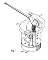
- FIG. 1 there is shown in perspective view, an ammunition magazine 10 in accordance with the present invention showing the magazine 10 an an operative relationship with a gun 12 mounted on a turret 14, all of which may be disposed on a transport vehicle (not shown).
- the magazine 10 communicates with the gun 12 via a pair of feed chutes 16, 18, extending from ports 24, 26, disposed in a top portion 28 of the drum-type housing. It should be appreciated that the feed chutes 16, 18, as well as the gun 12 and the turret 14, are not part of the present invention but are shown as a typical installation of the ammunition magazine 10.
- FIG. 2 An enlarged perspective view of the magazine 10, partially broken away, is shown in Figure 2.
- a center and an outside walls 38, 40, respectively, as well as the top 28 and a bottom 42 provides means defining an inner and an outer bay 46, 48, respectively, within the drum-type housing 30.
- bays for illustrative purposes only two bays, an inner and an outer, are shown; however, depending on the requirements of the magagzine 10, in accordance with the present invention, a greater number of bays may be employed.
- the illustrated configuration for the magazine of the present invention is for 25 mm caliber ammunition rounds 50 provides for the storage of 576 rounds of ammunition in the outer bay 48 which may be primary or high explosive ammunition, and 288 rounds of ammunition in the inner bay 46 which may be secondary or armour piercing ammunition.
- the outer bay 48 may have an outer radius of about 63 cm and the inner bay 46 may have an outer radius of about 36 cm with the height of the magazine being about 36 cm.
- each of the fixed partitions 52 have a gap therein to enable the ammunition rounds to transition from one fixed tiered partition to another as will be described hereinafter in greater detail.
- the fixed partitions 52 extend inwardly toward the center of the magazine to an extent necessary to support the approximately right cylindrical portion 56 of the ammunition round 50 (see Figure 4).
- the fixed partitions 52 are spaced apart a distance greater than the maximum diameter of the ammunition round 50 and support the rounds along direction defined by radii 58 of the drum-type housing.
- the partitions 52 may have an upturned portion 60 for supporting the round 50. This latter feature promotes low friction rolling of the round 50 on the fixed partition 52 as the rounds are moved within the bays 46, 48.
- Ammunition carriers 68, 70 concentrically and rotatably mounted within the inner and outer bays 46, '48, respectively, provide means for moving the ammunition rounds 50 within the inner and outer bays, respectively, and between the fixed partitions 52.
- Each ammunition carrier 68, 70 consists of eight carrier rings 76, attached to movable upright partitions 78, 80, respectively, having a series of cutouts 82 conforming to contour of an ammunition rounds 50.
- the ammunition rounds 50 ride, or roll, on the fixed partitions 52 within the confines of the cutouts 78 as the ammunition carrier is rotated by motors 84, 86, respectively.
- Bearings 88, 90 support the movable partitions 78, 80 at the bottom 40 of the magazine and bearings 92,94 support the movable partitions 78, 80 at the top 28 for rotation within the outer and inner bays 48, 46 respectively.
- each of the movable partitions 78, 80 Attached to each of the movable partitions 78, 80 are ring gears 100, 102 disposed for engagement with drive gears 104, 106 attached to the motor 84, 86 respectively.
- the carrier rings have inner and outer transfer tabs 108, 110 attached thereto for guiding or driving the ammunition rounds 50 during transition of the rounds from one fixed partition to an adjacent fixed partition.
- the transfer tabs 108, 110 add strength to the carrier rings 76 and help support the carrier rings in a spaced-apart relationship.
- the inner transfer tabs 108 are connected together between the carrier rings where as the outer tabs 110 are shorter and do not connect as they have a small running clearance with the fixed partitions 52.
- FIG 3 shows in detail ramps 112 extending between adjacent fixed partitions 52 which provide a means for transferring, or transitioning ammunition rounds from one fixed tiered position to another and thereafter to the correspondent port 24, 26, as each ammunition carrier 68, 70 is rotated by the motors 84, 86.
- a slot 114 is provided in each ramp 112 in order to enable the carrier rings 76 to pass therethrough.
- the magazine 10 construction is amenable to modular construction, and although not shown in the Figures, it is apparent that the carriers 76 and the center and outer walls 38, 40 may be readily designed as "bolt-together" layers which enables the rapid assembly of a magazine 10 of any desired capacity by assembling together as many layers as needed.
- the drive motors 84, 86 rotate the ammunition carriers via the drive gears 102, 104 and the ring gears 98, 110.
- the ammunition carrier 84, 86 are moved in a direction shown by arrows 116 in Figure 3 between the fixed partitions 52 they are driven upwardly from lower fixed partitions to higher fixed partitions along the ramps 112 by the transfer tabs 110 along the directions indicated by the arrow 118 until they reach the exit port 26 where they are taken from the part by handoff apparatus 120, the latter not being part of the present invention.
- the reloading of the magazine 10 can is rapidly achieved by running the motors in reverse and feeding ammunition to the handoff apparatus 120.
Abstract
Description
- The present invention relates generally to ammunition storage and more particularly to a volumetrically efficient drum-type ammunition magazine amenable for installation on transport vehicles having a turret type gun.
- It is to be appreciated that although the present invention has particular advantage for use in limited space and weight environments, such as aboard transport vehicles, ships and the like, the general principles taught by the invention may have use in other ammunition handling systems.
- As to limited space/weight applications, it is desirable that an ammunition magazine be volumetrically efficient, that is, hold a large number of rounds per unit volume. A linkless feed system is desirable in this regard, because linked ammunition necessarily includes the "dead" weight associated with the links which support and help guide the individual ammunition rounds.
- In addition, the rate of fire of modern guns may be hundreds or thousands of rounds per minute. This results in very high acceleration and deceleration in the ammunition supply system which make belts formed by cartridge carrying links unsatisfactory because of breakage or separation which may occur.
- Further, modern larger caliber guns, such as 25 mm, are capable of firing a variety of ammunition types such as high explosive, armour piercing, among others; hence, an ammunition magazine compatible with the weapon for utilizing this feature to its greatest advantage should be able to store more than one type of ammunition and be capable of feeding each type of ammunition to the weapon upon demand without significant interruption of the weapon firing rate.
- It is also important that the ammunition magazine be structurally compatible with the turret mounted weapon so that the magazine does not interfere with the range of motion of the turret or otherwise limit the firing envelope of the weapon. In many cases this requires the ammunition magazine to be installed in a remote position from the gun.
- Numerous other ammunition magazines that have a general DRUM-TYPE configuration have been invented in the past, and at least three types are known to be in current use. However, none are known that have the ability to independently feed two or more different types of ammunition.
- One known type consists of a fixed continuous helical outer partition to guide and support the ammunication case, and a rotating "stave" inner drive means to drive the ammunition rounds, by interface with the projectile and shoulder position of the round, around the fixed helical outer portion. It is easily appreciated that such a continuous outer helical guide is both difficult and expensive to manufacture. Also, because the outer helical guide must be continuous, the inner stave guide means must stop well short of extending radially outward to the base of the round, which results in unfavorable efficiencies and subsequent higher loads and power requirements.
- A second type consists of a rotating helical inner drive means (looking very much like a post- hole digging auger) which propels ammunition rounds axially, with the ammunition rounds being restrained and guided by fixed longitudinal tracks in the stationary outer drum. The apparent advantage of this type is that the multiple rows all progress very slowly toward the exit end of the drum. As the ammunition rounds move slowly, the inertia of the ammunition rounds is small which promotes the ability of the system to start very rapidly. Unfortunately, the speed and mass of the rotating center helix is quite large, which detracts from the apparent advantage obtained from low ammunition round velocity, and transmission of drive power to the ammunition round is poor due to high sliding velocities between the rotating center helix and the ammunition rounds. Further, the system is complicated because the ammunition rounds exits the drum at all radial positions, which requires an additional "Scoop Disc Assembly", or the like, to obtain a continuous single stream output at a fixed location. See U.S. Patent 2,935,914, issued to B. Darsie ET AL.
- A third type, which is in fact a variant of the second type, utilizes a fixed inner helix with a rotatable outer drum and longitudinal track assembly. This design eliminates the need of a Scoop Disc Assembly, but results in high round inertia.
- Drum-type ammunition magazines have heretofore been utilized such as in French Patent No. 2 407 645, which describes an ammunition magazine for storage and dispensing of linkless ammunition, having a drum-type housing with a top and a bottom, the drum-type housing being divided into a plurality of bays concentrically disposed within the drum-type housing with an inner bay being disposed adjacent the axis of the drum-type housing and outer bay being disposed outwardly from said inner bay. However, because ammunition rounds are axially stored therein, this type of magazine is volumetrically inefficient in the storage of ammunition therein.
- Further, U.S.
Patent 3 683 743 shows a drum-type ammunition magazine, which supports ammunition along radii of the magazine. However, it does not include the ability to independently feed one or more different types of ammunition upon demand without significant interruption of the weapon firing rate. - The present invention provides a lightweight volumetric efficient ammunition magazine capable of storing a plurality of different types of ammunition within a single magazine and separately delivering such different types of ammunition upon demand without the need for expensive helical guides or drive means.
- The present invention concerns an ammunition magazine including a drum-type housing and means defining a plurality of bays concentrically disposed within the drum-type housing. According to the invention the ammunition rounds within each of the concentrically disposed bays are supported along directions defined by radii of the drum-type housing.
- Further, ammunition carrier means, rotatably mounted within each concentrically disposed bay are provided for moving said ammunition rounds within the concentrically disposed bays and means are provided for rotating the ammunition carrier means within the concentrically disposed bays.
- More particularly, a magazine is provided for the storage and dispensing of linkless ammunition in which the drum-type housing has a top and a bottom therein and means defining a plurality of ports in the top for passage of linkless ammunition rounds therethrough. The means defining a plurality of concentric bays defines both an inner bay and an outer bay and the means for supporting the ammunition includes a plurality of fixed tiered partitions for supporting linkless ammunition rounds therein along directions defined by radii of the drum-type housing.
- Means are provided for separately rotating the ammunition carrier means within the inner and outer bays, and ramp means, interconnected between adjacent fixed tiered partitions, are provided for transferring linkless ammunition rounds from one fixed tiered partition to another and thereafter to the corresponding port as each ammunition carrier means is rotated.
- Tab means disposed on said ammunition carrier means and between each linkless ammunition round drive the linkless ammunition rounds along the ramp means from one fixed tiered partition to another as the ammunition carrier is rotated.
- Because the concentric bays are separately disposed in the drum-type housing and the ammunition carrier means may be operated separately from one another within each of the concentric bays, a different type of ammunition may be stored in each of the bays and separately withdrawn therefrom upon demand.
- As a further advantage of the present invention, the carrier means is highly efficient in moving the ammunition rounds within the magazine because it drives the ammunition rounds over their entire length and thereby enables the ammunition rounds to roll, rather than slide, which reduces frictional loading.
- The advantages and features of the present invention will appear from the following description which considered in conjunction with the accompanying drawings, in which:
- Figure 1 is a perspective view of the ammunition magazine according to the present invention in an operative relationship with a turret mounted automatic rapid fire gun as it may be employed on a transport vehicle and showing the ammunition magazine being disposed directly under the turret;
- Figure 2 is a perspective view of the drum-type housing of ammunition magazine partially broken away to show ammunition rounds disposed therein supported by a plurality of fixed tiered partitions disposed in concentrically disposed inner and outer bays and an ammunition carrier rotatably mounted within each of the inner and outer bays for separately moving the ammunition rounds within the inner and outer bays, respectively, as well as means for rotating the ammunition carriers within the concentrically disposed inner and outer bays;
- Figure 3 is a partial cross-section taken along the line 3-3 in Figure 2 showing in greater detail the fixed tiered partitions for supporting the ammunition rounds as well as ramps interconnected between adjacent fixed tiered partitions for transporting the ammunition rounds from one adjacent fixed tiered partition to another as the ammunition carrier is rotated;
- Figure 4 is a partial top view of the ammunition carrier showing the disposition of the ammunition rounds along directions defined by radii of the drum-type housing and between tabs disposed on the ammunition carriers for driving the ammunition rounds along the ramps (Figure 3) from one tiered partition to another; &
- Figure 5 is a partial cross-section of the inner and outer bay more clearly showing the relationship between the fixed tiered partitions and the ammunition carriers.
- Turning now to Figure 1 there is shown in perspective view, an
ammunition magazine 10 in accordance with the present invention showing themagazine 10 an an operative relationship with a gun 12 mounted on a turret 14, all of which may be disposed on a transport vehicle (not shown). - The
magazine 10 communicates with the gun 12 via a pair of feed chutes 16, 18, extending fromports top portion 28 of the drum-type housing. It should be appreciated that the feed chutes 16, 18, as well as the gun 12 and the turret 14, are not part of the present invention but are shown as a typical installation of theammunition magazine 10. - An enlarged perspective view of the
magazine 10, partially broken away, is shown in Figure 2. In general, a center and anoutside walls 38, 40, respectively, as well as thetop 28 and a bottom 42 provides means defining an inner and anouter bay 46, 48, respectively, within the drum-type housing 30. - It should be appreciated that for illustrative purposes only two bays, an inner and an outer, are shown; however, depending on the requirements of the
magagzine 10, in accordance with the present invention, a greater number of bays may be employed. - In addition, in as much as the
inner bay 46 and the outer bay 48 are similar except for size, the outer bay will be primarily described with all such description and comment applying to the inner bay except for specific differences as may be pointed out. - The illustrated configuration for the magazine of the present invention is for 25 mm
caliber ammunition rounds 50 provides for the storage of 576 rounds of ammunition in the outer bay 48 which may be primary or high explosive ammunition, and 288 rounds of ammunition in theinner bay 46 which may be secondary or armour piercing ammunition. The outer bay 48 may have an outer radius of about 63 cm and theinner bay 46 may have an outer radius of about 36 cm with the height of the magazine being about 36 cm. - Seven fixed tiered
circular partitions 52 are attached to the outer wall 40 for supporting theammunition rounds 50, and as shown in Figure 3, each of thefixed partitions 52 have a gap therein to enable the ammunition rounds to transition from one fixed tiered partition to another as will be described hereinafter in greater detail. Thefixed partitions 52 extend inwardly toward the center of the magazine to an extent necessary to support the approximately rightcylindrical portion 56 of the ammunition round 50 (see Figure 4). - The
fixed partitions 52 are spaced apart a distance greater than the maximum diameter of the ammunition round 50 and support the rounds along direction defined byradii 58 of the drum-type housing. - As best shown in Figure 5 the
inner bay 46, thepartitions 52 may have anupturned portion 60 for supporting theround 50. This latter feature promotes low friction rolling of theround 50 on thefixed partition 52 as the rounds are moved within thebays 46, 48. -
Ammunition carriers outer bays 46, '48, respectively, provide means for moving theammunition rounds 50 within the inner and outer bays, respectively, and between thefixed partitions 52. - Each
ammunition carrier upright partitions cutouts 82 conforming to contour of anammunition rounds 50. The ammunition rounds 50 ride, or roll, on thefixed partitions 52 within the confines of thecutouts 78 as the ammunition carrier is rotated bymotors 84, 86, respectively. -
Bearings 88, 90 support themovable partitions bearings 92,94 support themovable partitions top 28 for rotation within the outer andinner bays 48, 46 respectively. - Attached to each of the
movable partitions ring gears drive gears motor 84, 86 respectively. - As will be hereinafter discussed in connection with the operation of the
magazine 10, the carrier rings have inner andouter transfer tabs - Structurally, the
transfer tabs inner transfer tabs 108 are connected together between the carrier rings where as theouter tabs 110 are shorter and do not connect as they have a small running clearance with the fixedpartitions 52. - Figure 3 shows in detail ramps 112 extending between adjacent
fixed partitions 52 which provide a means for transferring, or transitioning ammunition rounds from one fixed tiered position to another and thereafter to thecorrespondent port ammunition carrier motors 84, 86. As shown in Figure 3 a slot 114 is provided in each ramp 112 in order to enable the carrier rings 76 to pass therethrough. - It should be appreciated that the
magazine 10 construction is amenable to modular construction, and although not shown in the Figures, it is apparent that the carriers 76 and the center andouter walls 38, 40 may be readily designed as "bolt-together" layers which enables the rapid assembly of amagazine 10 of any desired capacity by assembling together as many layers as needed. - In operation, the
drive motors 84, 86 rotate the ammunition carriers via the drive gears 102, 104 and the ring gears 98, 110. As theammunition carrier 84, 86 are moved in a direction shown by arrows 116 in Figure 3 between the fixedpartitions 52 they are driven upwardly from lower fixed partitions to higher fixed partitions along the ramps 112 by thetransfer tabs 110 along the directions indicated by the arrow 118 until they reach theexit port 26 where they are taken from the part byhandoff apparatus 120, the latter not being part of the present invention. - The reloading of the
magazine 10 can is rapidly achieved by running the motors in reverse and feeding ammunition to thehandoff apparatus 120. - Although there has been described hereinabove a particular arrangement of an ammunition magazine in accordance with the present invention for the purpose of illustrating the manner in which the invention may be used to advantage, it should be appreciated that the invention as defined in the claims is not limited thereto.
Claims (8)
Priority Applications (1)
| Application Number | Priority Date | Filing Date | Title |
|---|---|---|---|
| AT83105474T ATE30079T1 (en) | 1982-06-07 | 1983-06-02 | DRUM-SHAPED CARTRIDGE MAGAZINE. |
Applications Claiming Priority (2)
| Application Number | Priority Date | Filing Date | Title |
|---|---|---|---|
| US06/385,506 US4457208A (en) | 1982-06-07 | 1982-06-07 | Drum-type ammunition magazine |
| US385506 | 1982-06-07 |
Publications (3)
| Publication Number | Publication Date |
|---|---|
| EP0096376A2 EP0096376A2 (en) | 1983-12-21 |
| EP0096376A3 EP0096376A3 (en) | 1984-10-17 |
| EP0096376B1 true EP0096376B1 (en) | 1987-09-30 |
Family
ID=23521666
Family Applications (1)
| Application Number | Title | Priority Date | Filing Date |
|---|---|---|---|
| EP83105474A Expired EP0096376B1 (en) | 1982-06-07 | 1983-06-02 | Drum-type ammunition magazine |
Country Status (5)
| Country | Link |
|---|---|
| US (1) | US4457208A (en) |
| EP (1) | EP0096376B1 (en) |
| AT (1) | ATE30079T1 (en) |
| CA (1) | CA1206360A (en) |
| DE (1) | DE3373936D1 (en) |
Families Citing this family (10)
| Publication number | Priority date | Publication date | Assignee | Title |
|---|---|---|---|---|
| EP0152549A1 (en) * | 1983-12-22 | 1985-08-28 | Werkzeugmaschinenfabrik Oerlikon-Bührle AG | Device for feeding ammunition to a gun |
| US4753155A (en) * | 1987-02-04 | 1988-06-28 | Balister Albert M | Ammunition box for machine gun |
| US4781100A (en) * | 1987-06-08 | 1988-11-01 | Western Design Corporation | Linkless ammunition gun transfer unit |
| US4831914A (en) * | 1987-07-08 | 1989-05-23 | David Dardick | Multiple tier ammunition magazine |
| US4882971A (en) * | 1988-05-27 | 1989-11-28 | Teleflex, Incorporated | Linkless ammunition transporter |
| US4873911A (en) * | 1988-11-21 | 1989-10-17 | General Dynamics Land Systems, Inc. | Double loop ammunition magazine of compact construction |
| AT398738B (en) * | 1991-09-19 | 1995-01-25 | Plasser Bahnbaumasch Franz | METHOD FOR MOUNTING TRAILERS ON A CABLE |
| US6684873B1 (en) * | 2002-09-04 | 2004-02-03 | Joel A. Anderson | Paint ball gun magazine with tilt sensor |
| US8291806B2 (en) | 2010-12-27 | 2012-10-23 | Paul J Rael | Helical ammunition magazine |
| FR3017202B1 (en) * | 2014-02-06 | 2016-08-05 | Nexter Systems | CARTRIDGE FEEDING DEVICE FOR A TURRET AND CARTRIDGE LOADING METHOD OF SUCH A DEVICE |
Family Cites Families (15)
| Publication number | Priority date | Publication date | Assignee | Title |
|---|---|---|---|---|
| US1303028A (en) * | 1919-05-06 | George henry william cashmobe | ||
| US290622A (en) * | 1883-12-18 | accles | ||
| US1329979A (en) * | 1916-05-16 | 1920-02-03 | Lang Charles Welington | Rapid-fire gun |
| US1256924A (en) * | 1916-08-22 | 1918-02-19 | Savage Arms Corp | Cartridge-guide for firearms. |
| US1335677A (en) * | 1917-04-09 | 1920-03-30 | Ansley H Fox Company | Magazine or cartridge feeding device for automatic machine-guns |
| US1330873A (en) * | 1918-04-10 | 1920-02-17 | Armes Automatique Lewis Sa | Magazine |
| US1337893A (en) * | 1918-12-30 | 1920-04-20 | Farquhar Moubray Gore | Cartridge-magazine for rifles and machine-guns |
| US1394494A (en) * | 1919-07-02 | 1921-10-18 | Samuel G Green | Safety and guide attachment for machine-gun magazines |
| BE376420A (en) * | 1930-02-10 | |||
| GB573211A (en) * | 1941-07-26 | 1945-11-12 | Josef Vesely | Improvements in or relating to magazines for fire arms |
| US2833182A (en) * | 1955-12-05 | 1958-05-06 | Gen Electric | Ammunition storing and feeding device |
| US2935914A (en) * | 1957-08-05 | 1960-05-10 | Darsie Burns | Linkless feed system for guns |
| US3498178A (en) * | 1968-02-23 | 1970-03-03 | Emerson Electric Co | Cylindrical ammunition magazine for storing and discharging linked ammunition |
| US3683743A (en) * | 1969-08-01 | 1972-08-15 | Stoner Eugen Morrison | Linkless cartridge feed system |
| GB1523432A (en) * | 1971-10-29 | 1978-08-31 | Marconi Co Ltd | Turret gun arrangements |
-
1982
- 1982-06-07 US US06/385,506 patent/US4457208A/en not_active Expired - Lifetime
-
1983
- 1983-04-28 CA CA000426886A patent/CA1206360A/en not_active Expired
- 1983-06-02 EP EP83105474A patent/EP0096376B1/en not_active Expired
- 1983-06-02 DE DE8383105474T patent/DE3373936D1/en not_active Expired
- 1983-06-02 AT AT83105474T patent/ATE30079T1/en active
Also Published As
| Publication number | Publication date |
|---|---|
| EP0096376A3 (en) | 1984-10-17 |
| ATE30079T1 (en) | 1987-10-15 |
| DE3373936D1 (en) | 1987-11-05 |
| EP0096376A2 (en) | 1983-12-21 |
| US4457208A (en) | 1984-07-03 |
| CA1206360A (en) | 1986-06-24 |
Similar Documents
| Publication | Publication Date | Title |
|---|---|---|
| EP0096376B1 (en) | Drum-type ammunition magazine | |
| KR910003038B1 (en) | Drum magazine | |
| US4681018A (en) | Cartridge feed mechanism | |
| US4424735A (en) | Linear linkless ammunition magazine | |
| US2951422A (en) | Article handling system for cartridge feeding | |
| US5107750A (en) | Feeding ammunition | |
| US4166408A (en) | Ammunition handling system | |
| US3974738A (en) | Rotary differential ammunition reservoir | |
| EP0091772B1 (en) | Transport mechanism for ammunition | |
| US3376785A (en) | Installation for loading the launching tubes of a depth-charge launcher | |
| US2935914A (en) | Linkless feed system for guns | |
| EP0480630B1 (en) | Ammunition storage system | |
| JPH02133800A (en) | Projectile-feed device | |
| US6272967B1 (en) | Modular ammunition storage and retrieval system | |
| RU201560U1 (en) | SHIP ARTILLERY AMMUNITION SHOP | |
| US3766823A (en) | Ammunition handling system | |
| EP0493918B1 (en) | Magazine and conveyor | |
| US5170006A (en) | Propellant magazine for field artillery piece | |
| US5149909A (en) | Opposed round parallel path single bay ammunition feed system | |
| US2891448A (en) | Feeding installation for feeding rounds of ammunition from a magazine to a hoist | |
| USH164H (en) | High capacity magazine for weapons | |
| US4831914A (en) | Multiple tier ammunition magazine | |
| US6481328B1 (en) | Method and device for handling propellant charges | |
| US2905056A (en) | Feeder device for the automatic loading of guns | |
| US5109751A (en) | Parallel path single bay ammunition feed system |
Legal Events
| Date | Code | Title | Description |
|---|---|---|---|
| PUAI | Public reference made under article 153(3) epc to a published international application that has entered the european phase |
Free format text: ORIGINAL CODE: 0009012 |
|
| AK | Designated contracting states |
Designated state(s): AT BE CH DE FR GB IT LI LU NL SE |
|
| PUAL | Search report despatched |
Free format text: ORIGINAL CODE: 0009013 |
|
| AK | Designated contracting states |
Designated state(s): AT BE CH DE FR GB IT LI LU NL SE |
|
| 17P | Request for examination filed |
Effective date: 19850118 |
|
| 17Q | First examination report despatched |
Effective date: 19860418 |
|
| GRAA | (expected) grant |
Free format text: ORIGINAL CODE: 0009210 |
|
| AK | Designated contracting states |
Kind code of ref document: B1 Designated state(s): AT BE CH DE FR GB IT LI LU NL SE |
|
| PG25 | Lapsed in a contracting state [announced via postgrant information from national office to epo] |
Ref country code: NL Effective date: 19870930 Ref country code: BE Effective date: 19870930 Ref country code: AT Effective date: 19870930 |
|
| REF | Corresponds to: |
Ref document number: 30079 Country of ref document: AT Date of ref document: 19871015 Kind code of ref document: T |
|
| REF | Corresponds to: |
Ref document number: 3373936 Country of ref document: DE Date of ref document: 19871105 |
|
| ET | Fr: translation filed | ||
| ITF | It: translation for a ep patent filed |
Owner name: STUDIO TORTA SOCIETA' SEMPLICE |
|
| NLV1 | Nl: lapsed or annulled due to failure to fulfill the requirements of art. 29p and 29m of the patents act | ||
| PG25 | Lapsed in a contracting state [announced via postgrant information from national office to epo] |
Ref country code: LU Free format text: LAPSE BECAUSE OF NON-PAYMENT OF DUE FEES Effective date: 19880630 |
|
| PLBE | No opposition filed within time limit |
Free format text: ORIGINAL CODE: 0009261 |
|
| STAA | Information on the status of an ep patent application or granted ep patent |
Free format text: STATUS: NO OPPOSITION FILED WITHIN TIME LIMIT |
|
| 26N | No opposition filed | ||
| PG25 | Lapsed in a contracting state [announced via postgrant information from national office to epo] |
Ref country code: GB Effective date: 19890602 |
|
| PG25 | Lapsed in a contracting state [announced via postgrant information from national office to epo] |
Ref country code: SE Effective date: 19890603 |
|
| ITTA | It: last paid annual fee | ||
| GBPC | Gb: european patent ceased through non-payment of renewal fee | ||
| PG25 | Lapsed in a contracting state [announced via postgrant information from national office to epo] |
Ref country code: FR Free format text: LAPSE BECAUSE OF NON-PAYMENT OF DUE FEES Effective date: 19900228 |
|
| REG | Reference to a national code |
Ref country code: FR Ref legal event code: ST |
|
| PGFP | Annual fee paid to national office [announced via postgrant information from national office to epo] |
Ref country code: CH Payment date: 19920519 Year of fee payment: 10 |
|
| PG25 | Lapsed in a contracting state [announced via postgrant information from national office to epo] |
Ref country code: LI Effective date: 19930630 Ref country code: CH Effective date: 19930630 |
|
| REG | Reference to a national code |
Ref country code: CH Ref legal event code: PL |
|
| EUG | Se: european patent has lapsed |
Ref document number: 83105474.7 Effective date: 19900412 |
|
| PGFP | Annual fee paid to national office [announced via postgrant information from national office to epo] |
Ref country code: DE Payment date: 19980527 Year of fee payment: 16 |
|
| PG25 | Lapsed in a contracting state [announced via postgrant information from national office to epo] |
Ref country code: DE Free format text: LAPSE BECAUSE OF NON-PAYMENT OF DUE FEES Effective date: 20000503 |