EP0096366B1 - Electrostatic draining device for cocks with a spherical surface - Google Patents
Electrostatic draining device for cocks with a spherical surface Download PDFInfo
- Publication number
- EP0096366B1 EP0096366B1 EP83105457A EP83105457A EP0096366B1 EP 0096366 B1 EP0096366 B1 EP 0096366B1 EP 83105457 A EP83105457 A EP 83105457A EP 83105457 A EP83105457 A EP 83105457A EP 0096366 B1 EP0096366 B1 EP 0096366B1
- Authority
- EP
- European Patent Office
- Prior art keywords
- ball
- spring
- spindle
- contact
- bushing
- Prior art date
- Legal status (The legal status is an assumption and is not a legal conclusion. Google has not performed a legal analysis and makes no representation as to the accuracy of the status listed.)
- Expired
Links
Images
Classifications
-
- H—ELECTRICITY
- H05—ELECTRIC TECHNIQUES NOT OTHERWISE PROVIDED FOR
- H05F—STATIC ELECTRICITY; NATURALLY-OCCURRING ELECTRICITY
- H05F3/00—Carrying-off electrostatic charges
- H05F3/02—Carrying-off electrostatic charges by means of earthing connections
Definitions
- the invention relates to a device for electrostatic discharge in ball valves by means of a contact element between a valve ball and a spindle and a second contact element between the spindle and a stuffing box or nut.
- the ball must be grounded via the spindle in ball valves used in the chemical industry. This is necessary because the ball can become electrostatically charged and explosions can occur when using explosive or other dangerous media.
- the slip rings used lose tension very quickly, so that a lifting, even if only very slight, from the spindle is detected. Even during maintenance work on the housing of the ball valves, the contact spring can be damaged unnoticed, so that its functionality is restricted.
- the object of the invention is to provide inexpensive devices for electrostatic discharge in a ball valve of the type mentioned, which are no longer exposed to external influences and influences of the media used.
- the devices must be easy to install and protected from damage during maintenance work.
- the contact pins used are about 90% cheaper than the usual spring arrangements. The reason for this is that the contact pins for the watch industry are manufactured in very large numbers. These are used as holding pins for bracelets on wristwatches.
- the contact pins are very easy to use and are used between the ball and the spindle. It is no longer necessary to carry easily damaged parts with you during maintenance work, just the insensitive pins.
- the spring Due to the coating of the pens, the spring is no longer exposed to the often very aggressive media found in the chemical industry. Even during maintenance work, damage to the contact pins can no longer occur.
- the pins as well as the sleeves can be made of stainless steel and are therefore ideal when using aggressive media. It has also been shown that the time required for attaching the contact pins is considerably less than when using the previously customary contact arrangements. In addition to the advantage of the lower purchase price, there is also time savings during assembly.
- the sprung ball is also a part that is found very often in industry and is therefore available on the market at very low cost. It has been found to be advantageous that the sleeve has a thread on the outside for screwing into the part surrounding the spindle. A slot for engaging a screwdriver is made in the end of the sleeve opposite the contact ball.
- the sleeve can be made of stainless steel.
- the pin mentioned above can also be attached. Due to the electrostatic dissipation by means of two metal pins or a metal pin and a spring-loaded ball, the solution to the underlying is thus in both cases in the ball valve according to the invention Task reliably guaranteed.
- the embodiment working with a pin and a ball ensures smooth operation and reliable wear-free operation while maintaining reliable contact.
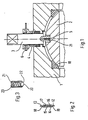
- the housing 1 of the ball valve there is a round opening in the middle on the upper side.
- a spindle 3 which is surrounded by a stuffing box or nut 4, passes through this opening.
- the ball has a square recess in the upper part, in which a pin 21 engages. This pin is at the lower end of the spindle. A hole is provided in this pin which receives the contact pin 5.
- the contact pin consists of a sleeve 14, preferably made of metal, two metal pins 12, 13 and a spring 15.
- the sleeve has an inwardly directed flanged edge 18, 19 on both sides.
- a spring is arranged between the two metal pins and tends to push the two metal pins away from one another.
- the two metal pins each have a shoulder 16, 17 at their inner ends. Thus, the two metal pins cannot be pressed out of the sleeve by the spring force.
- the spindle 3 is surrounded by a stuffing box or nut 4. This stuffing box or nut is firmly connected to the housing. As a result, the spindle is firmly guided in the opening of the housing.
- a bore is provided in the stuffing box or nut which has a thread and has the same diameter as the bore which receives the contact pin 5. This bore in the stuffing box or nut receives the sprung ball 6.
- the spring-loaded ball 6 is seated in a sleeve 21, preferably made of metal, which is closed at one end and has an opening at the other end, which has an inwardly directed flanged edge 22.
- a sleeve 21 preferably made of metal, which is closed at one end and has an opening at the other end, which has an inwardly directed flanged edge 22.
- the spring 23 being supported at one end against the closed sleeve, with the other end pushing the ball 20 outwards.
- the ball 20 has a larger diameter than the opening formed by the flange 22. Thus, the ball 20 cannot be pressed out of the sleeve 21 by the spring force.
- a pin as shown in FIG. 2 can also be used between the spindle and the stuffing box or nut.
Description
Die Erfindung betrifft eine Vorrichtung zur elektrostatischen Ableitung bei Kugelhähnen mittels eines Kontaktelementes zwischen einer Ventilkugel und einer Spindel und eines zweiten Kontaktelementes zwischen der Spindel und einer Stopfbuchse oder -mutter.The invention relates to a device for electrostatic discharge in ball valves by means of a contact element between a valve ball and a spindle and a second contact element between the spindle and a stuffing box or nut.
Aufgrund strenger Sicherheitsvorschriften muß bei in der chemischen Industrie verwendeten Kugelhähnen die Kugel über die Spindel geerdet sein. Dies ist erforderlich, da sich die Kugel elektrostatisch aufladen kann und bei Verwendung explosiver oder sonstiger gefährlicher Medien Explosionen stattfinden können.Due to strict safety regulations, the ball must be grounded via the spindle in ball valves used in the chemical industry. This is necessary because the ball can become electrostatically charged and explosions can occur when using explosive or other dangerous media.
Durch diese Sicherheitsvorschriften wurde es notwendig, eine metallische Verbindung zwischen der Kugel und der Spindel und zwischen der Spindel und dem geerdeten Gehäuse herzustellen. Dazu werden gemäß dem Stand der Technik zwischen der Kugel und Spindel Federn, Federplättchen oder angefederte Kugeln angebracht. Eine Ableitung der Spindel wird dadurch zu erreichen versucht, daß an der Stopfbuchse bzw. -mutter Schleifringe oder Federn angeschraubt werden, die eine ständige Berührung der Spindel gewährleisten sollen. Gemäß der DE-OS-23 28 955 ist bekannt, zur elektrostatisch leitenden Verbindung zwischen Kugel und geerdetem Gehäuse eine Feder oder eine kleine Kugel zwischen diesen Bauteilen anzuordnen.These safety regulations made it necessary to establish a metallic connection between the ball and the spindle and between the spindle and the grounded housing. For this purpose, springs, spring plates or spring-loaded balls are attached between the ball and spindle according to the prior art. An attempt is made to derive the spindle by screwing slip rings or springs onto the stuffing box or nut, which are intended to ensure constant contact with the spindle. According to DE-OS-23 28 955 it is known to arrange a spring or a small ball between these components for the electrostatically conductive connection between the ball and the grounded housing.
Aus der Zeitschrift "Polytechnisch Tijdschrift Werktinghouw", Band 31, Nr. 1, 1976, Seiten 33 - 39, STAM BV, Den Haag (NL), Abbildung 9, ist es ferner bekannt, zur elektrostatisch leitenden Verbindung zwischen Kugel und Gehäuse und zwischen Spindel und Gehäuse einen angefederten Stift zwischen diesen Bauteilen anzuordnen.From the magazine "Polytechnisch Tijdschrift Werktinghouw", Volume 31, No. 1, 1976, pages 33 - 39, STAM BV, Den Haag (NL), Figure 9, it is also known for the electrostatically conductive connection between ball and housing and between Spindle and housing to arrange a sprung pin between these components.
Diese Anordnungen können die geforderten Sicherheitsbestimmungen jedoch nur teilweise erfüllen. Bei den verwendeten Kontaktelementen zwischen Kugel und Spindel tritt immer wieder das Problem auf, daß die Federanordnung aggressiven Medien voll ausgesetzt ist und somit schon nach kurzer Betriebsdauer unvorhergesehen schnell Beschädigungen auftreten, die ein permanentes Anliegen des Kontaktelementes sowohl an der Spindel als auch an der Kugel nicht mehr gewährleisten. Bei Wartungsarbeiten, bei denen die Spindel herausgenommen wird, ist die Feder bzw. die Anordnung der angefederten Kugel jeder Art von Beschädigungen ausgesetzt; bei Demontage der Spindel wird somit sehr häufig gleich die Kontaktfeder mit ersetzt, um nicht Gefahr zu laufen, eine beschädigte Feder oder angefederte Kugel wieder einzubauen.However, these arrangements can only partially meet the required safety regulations. In the contact elements used between the ball and the spindle, the problem arises again and again that the spring arrangement is fully exposed to aggressive media and, after a short period of operation, damage occurs unexpectedly quickly, which does not result in permanent contact of the contact element with either the spindle or the ball ensure more. During maintenance work in which the spindle is removed, the spring or the arrangement of the spring-loaded ball is exposed to any kind of damage; when the spindle is dismantled, the contact spring is very often replaced at the same time so as not to run the risk of reinstalling a damaged spring or spring-loaded ball.
Bei der bisher üblichen Ableitung zwischen Spindel und Stopfbuchse bzw. -mutter verlieren die verwendeten Schleifringe sehr schnell an Spannung, so daß ein, wenn auch nur sehr geringes Abheben von der Spindel festgestellt wird. Auch bei Wartungsarbeiten am Gehäuse der Kugelhähne kann die Kontaktfeder unbemerkt beschädigt werden, so daß diese in ihrer Funktionsfähigkeit eingeschränkt ist.With the previously common derivation between the spindle and the stuffing box or nut, the slip rings used lose tension very quickly, so that a lifting, even if only very slight, from the spindle is detected. Even during maintenance work on the housing of the ball valves, the contact spring can be damaged unnoticed, so that its functionality is restricted.
Aufgabe der Erfindung ist es, bei einem Kugelhahn der eingangs genannten Art kostengünstige Vorrichtungen zur elektrostatischen Ableitung zu schaffen, die äußeren Einflüssen und Einflüssen der verwendeten Medien nicht mehr ausgesetzt sind. Dabei müssen die Vorrichtungen leicht eingebaut werden können und bei Wartungsarbeiten vor Beschädigungen geschützt sein.The object of the invention is to provide inexpensive devices for electrostatic discharge in a ball valve of the type mentioned, which are no longer exposed to external influences and influences of the media used. The devices must be easy to install and protected from damage during maintenance work.
Gelöst wird die Aufgabe durch die im kennzeichnenden Teil des Anspruchs 1 genannten Merkmale. Bevorzugte Ausgestaltungen ergeben sich aus den Unteransprüchen.The object is achieved by the features mentioned in the characterizing part of claim 1. Preferred configurations result from the subclaims.
Die verwendeten Kontaktstifte sind gegenüber den üblichen Federanordnungen um ca. 90 % billiger. Der Grund dafür ist, daß die Kontaktstifte für die Uhrenindustrie in sehr grossen Stückzahlen hergestellt werden. Verwendung finden diese als Haltestifte für Armbänder an Armbanduhren.The contact pins used are about 90% cheaper than the usual spring arrangements. The reason for this is that the contact pins for the watch industry are manufactured in very large numbers. These are used as holding pins for bracelets on wristwatches.
Die Kontaktstifte sind sehr leicht zu handhaben und werden zwischen Kugel und Spindel verwendet. Dabei müssen bei Wartungsarbeiten nicht mehr leicht beschädigbare Teile mitgeführt werden, sondern nur noch die unempfindlichen Stifte.The contact pins are very easy to use and are used between the ball and the spindle. It is no longer necessary to carry easily damaged parts with you during maintenance work, just the insensitive pins.
Durch die Ummantelung der Stifte ist die Feder den oft sehr aggressiven Medien, wie sie in der chemischen Industrie angetroffen werden, nicht mehr ausgesetzt. Auch bei Wartungsarbeiten können Beschädigungen an den Kontaktstiften nicht mehr auftreten.Due to the coating of the pens, the spring is no longer exposed to the often very aggressive media found in the chemical industry. Even during maintenance work, damage to the contact pins can no longer occur.
Die Stifte als auch die Hülsen können aus rostfreiem Edelstahl bestehen und eignen sich somit bestens bei Verwendung von aggressiven Medien. Auch hat sich gezeigt, daß die Zeitvorgabe für das Anbringen der Kontaktstifte erheblich geringer ist als bei Verwendung der bisher üblichen Kontaktanordnungen. Zu dem Vorteil des billigeren Anschaffungspreises tritt nun auch die Zeitersparnis bei der Montage.The pins as well as the sleeves can be made of stainless steel and are therefore ideal when using aggressive media. It has also been shown that the time required for attaching the contact pins is considerably less than when using the previously customary contact arrangements. In addition to the advantage of the lower purchase price, there is also time savings during assembly.
Bei der angefederten Kugel handelt es sich ebenfalls um ein Teil, das in der Industrie sehr häufig angetroffen wird und somit sehr kostengünstig auf dem Markt erhältlich ist. Von Vorteil hat sich dabei herausgestellt, daß die Hülse außen ein Gewinde zum Einschrauben in das die Spindel umgebende Teil aufweist. Im der Kontaktkugel entgegengesetzten Ende der Hülse ist ein Schlitz zum Eingreifen eines Schraubenziehers angebracht. Dabei kann die Hülse aus rostfreiem Edelstahl bestehen.The sprung ball is also a part that is found very often in industry and is therefore available on the market at very low cost. It has been found to be advantageous that the sleeve has a thread on the outside for screwing into the part surrounding the spindle. A slot for engaging a screwdriver is made in the end of the sleeve opposite the contact ball. The sleeve can be made of stainless steel.
Anstelle der angefederten Kugel zwischen der Spindel und Stopfbuchse bzw. -mutter kann auch der oben erwähnte Stift angebracht werden. Durch die elektrostatische Ableitung mittels zweier Metallstifte oder eines Metallstiftes und einer angefederten Kugel ist beim erfindungsgemäßen Kugelhahn somit in beiden Fällen die Lösung der zugrundeliegenden Aufgabe zuverlässig gewährleistet. Die mit einem Stift und einer Kugel arbeitende Ausführungsform stellt dabei unter Beibehaltung sicherer Kontaktgabe eine leichtgängige und zuverlässig verschleißfreie Betätigung sicher.Instead of the spring-loaded ball between the spindle and stuffing box or nut, the pin mentioned above can also be attached. Due to the electrostatic dissipation by means of two metal pins or a metal pin and a spring-loaded ball, the solution to the underlying is thus in both cases in the ball valve according to the invention Task reliably guaranteed. The embodiment working with a pin and a ball ensures smooth operation and reliable wear-free operation while maintaining reliable contact.
In den Zeichnungen wird ein Ausführungsbeispiel der Erfindung dargestellt.
- Fig. 1 zeigt einen Vertikalschnitt des oberen Teils eines Kugelhahns;
- Fig. 2 zeigt einen Vertikalschnitt des Kontaktstiftes;
- Fig. 3 zeigt einen Vertikalschnitt der angefederten Kontaktkugel.
- Fig. 1 shows a vertical section of the upper part of a ball valve;
- Fig. 2 shows a vertical section of the contact pin;
- Fig. 3 shows a vertical section of the spring-loaded contact ball.
Im Gehäuse 1 des Kugelhahnes befindet sich auf der oberen Seite mittig eine runde Öffnung. Durch diese Öffnung führt eine Spindel 3, die von einer Stopfbuchse bzw. -mutter 4 umgeben wird. Innerhalb des Gehäuses befindet sich eine Kugel 2. Diese hat einen geringeren Durchmesser als die jeweilige Ausnehmung im Gehäuse und wird in dieser Ausnehmung mittig durch einen Dichtungsring 10 gehalten. Die Kugel hat im oberen Teil eine quadratische Ausnehmung, in die ein Zapfen 21 eingreift. Dieser Zapfen befindet sich am unteren Ende der Spindel. In diesem Zapfen ist mittg eine Bohrung vorgesehen, die den Kontaktstift 5 aufnimmt.In the housing 1 of the ball valve there is a round opening in the middle on the upper side. A
Der Kontaktstift besteht aus einer Hülse 14 vorzugsweise aus Metall, zwei Metallstiften 12, 13 und einer Feder 15. Die Hülse weist auf beiden Seiten einen nach innen gerichteten Bördelrand 18,19 auf. Zwischen den beiden Metallstiften ist eine Feder angeordnet, die das Bestreben hat, die beiden Metallstifte voneinander wegzudrücken. Die beiden Metallstifte besitzen an ihren inneren Enden jeweils eine Schulter 16, 17. Somit können die beiden Metallstifte durch die Federkraft nicht aus der Hülse herausgedrückt werden.The contact pin consists of a
Die Spindel 3 wird von einer Stopfbuchse bzw. -mutter 4 umgeben. Diese Stopfbuchse bzw. -mutter wird fest mit dem Gehäuse verbunden. Dadurch wird die Spindel in der Öffnung des Gehäuses fest geführt.The
In der Stopfbuchse bzw. -mutter ist eine Bohrung vorgesehen, die ein Gewinde aufweist und den gleichen Durchmesser hat wie die Bohrung, die den Kontaktstift 5 aufnimmt. Diese Bohrung in der Stopfbuchse bzw. -mutter nimmt die angefederte Kugel 6 auf.A bore is provided in the stuffing box or nut which has a thread and has the same diameter as the bore which receives the
Die angefederte Kugel 6 sitzt in einer Hülse 21 vorzugsweise aus Metall, die an dem einen Ende geschlossen ist, am anderen Ende eine Öffnung aufweist, die einen nach innen gerichteten Bördelrand 22 hat. In dieser Hülse befindet sich eine Kugel 20 und eine Feder 23, wobei die Feder 23 sich am einen Ende gegen die geschlossene Hülse abstützt, mit dem anderen Ende die Kugel 20 nach außen drückt. Die Kugel 20 weist einen größeren Durchmesser auf als die Öffnung, die vom Bördelrand 22 gebildet wird. Somit kann die Kugel 20 durch die Federkraft nicht aus der Hülse 21 herausgedrückt werden. Es kann jedoch auch ein Stift wie in Fig. 2 dargestellt zwischen Spindel und Stopfbuchse bzw. -mutter verwendet werden.The spring-loaded
Claims (7)
Priority Applications (1)
| Application Number | Priority Date | Filing Date | Title |
|---|---|---|---|
| AT83105457T ATE32010T1 (en) | 1982-06-04 | 1983-06-01 | DEVICE FOR ELECTROSTATIC DISCHARGE FOR BALL VALVES. |
Applications Claiming Priority (4)
| Application Number | Priority Date | Filing Date | Title |
|---|---|---|---|
| DE3221258 | 1982-06-04 | ||
| DE19823221258 DE3221258C1 (en) | 1982-06-04 | 1982-06-04 | Ball valve having devices for electrostatic discharging to the earthed housing |
| DE8311255U | 1983-04-15 | ||
| DE8311255 | 1983-04-15 |
Publications (3)
| Publication Number | Publication Date |
|---|---|
| EP0096366A2 EP0096366A2 (en) | 1983-12-21 |
| EP0096366A3 EP0096366A3 (en) | 1985-06-12 |
| EP0096366B1 true EP0096366B1 (en) | 1988-01-13 |
Family
ID=25802271
Family Applications (1)
| Application Number | Title | Priority Date | Filing Date |
|---|---|---|---|
| EP83105457A Expired EP0096366B1 (en) | 1982-06-04 | 1983-06-01 | Electrostatic draining device for cocks with a spherical surface |
Country Status (2)
| Country | Link |
|---|---|
| EP (1) | EP0096366B1 (en) |
| DE (1) | DE3375354D1 (en) |
Families Citing this family (6)
| Publication number | Priority date | Publication date | Assignee | Title |
|---|---|---|---|---|
| FR2636513A1 (en) * | 1988-09-20 | 1990-03-23 | Maurel Jacques | Anti-static underframe for office chair |
| ITBO20020358A1 (en) * | 2002-06-07 | 2003-12-09 | Magneti Marelli Powertrain Spa | BUTTERFLY VALVE FOR AN INTERNAL COMBUSTION ENGINE WITH ELECTROSTATIC CHARGE DISSIPATOR AND RELATED ACTUATOR |
| CN103307303A (en) * | 2013-07-01 | 2013-09-18 | 自贡信赖泵阀制造有限公司 | Three-position pipeline-cleaning type three-way spherical valve |
| DE102017119205A1 (en) | 2017-08-22 | 2019-02-28 | Samson Ag | Control valve |
| DE202017105035U1 (en) | 2017-08-22 | 2018-11-23 | Samson Ag | Control valve |
| DE202018105866U1 (en) | 2018-10-12 | 2018-11-15 | Samson Ag | Valve |
Family Cites Families (3)
| Publication number | Priority date | Publication date | Assignee | Title |
|---|---|---|---|---|
| FR545514A (en) * | 1921-10-20 | 1922-10-13 | Electric socket with ball joint | |
| GB381354A (en) * | 1931-10-26 | 1932-10-06 | Macintosh Cable Company Ltd | An improved electrical joint, coupling or connection |
| FR2398241A1 (en) * | 1977-07-21 | 1979-02-16 | Gachot Jean | Ball valve for use with flammable liquids or vapours - has springs pressing on ball to conduct static electricity to earth |
-
1983
- 1983-06-01 EP EP83105457A patent/EP0096366B1/en not_active Expired
- 1983-06-01 DE DE8383105457T patent/DE3375354D1/en not_active Expired
Also Published As
| Publication number | Publication date |
|---|---|
| EP0096366A3 (en) | 1985-06-12 |
| DE3375354D1 (en) | 1988-02-18 |
| EP0096366A2 (en) | 1983-12-21 |
Similar Documents
| Publication | Publication Date | Title |
|---|---|---|
| EP0528204A1 (en) | Box with clamping means | |
| DE3431037A1 (en) | SOLENOID VALVE FOR VACUUM APPLICATION | |
| EP0096366B1 (en) | Electrostatic draining device for cocks with a spherical surface | |
| DE2135178A1 (en) | Filtering device for fluids | |
| DE102013106595A1 (en) | Opening and closing valve | |
| DD202065A5 (en) | DEVICE FOR FASTENING A COVER TO A HOUSING, ESPECIALLY ON A SLIDING CABINET | |
| DE112008001364T5 (en) | Connector for fluid pressure devices | |
| DE3221258C1 (en) | Ball valve having devices for electrostatic discharging to the earthed housing | |
| DE2734853C2 (en) | Filters for cleaning liquids | |
| DE1400767A1 (en) | Safety device with springy, curved safety washer | |
| DE901612C (en) | Securing device for assembling a gate valve | |
| DE8311255U1 (en) | DEVICE FOR ELECTROSTATIC DISCHARGE IN BALL VALVES TO THE GROUNDED HOUSING | |
| DE3017111C2 (en) | Woltmann water meter | |
| DE3907815C2 (en) | ||
| DE2352297C2 (en) | Damping device for an accumulator valve | |
| DE102017129585A1 (en) | Circlip for securing a component in a bore and assembly with such a retaining ring | |
| DE7907144U1 (en) | VALVE, IN PARTICULAR SAFETY VALVE FOR LUBRICATION SYSTEMS | |
| CH675506A5 (en) | ||
| EP3021017A1 (en) | Safety valve | |
| DE574916C (en) | Reset device for indicator flaps loosely mounted on a common axis | |
| CH712766B1 (en) | Eccentric bolt. | |
| DE8216355U1 (en) | BALL ROAD | |
| DE1252006B (en) | ||
| DE3126376A1 (en) | SHUT-OFF ORGANS FOR FLUIDS WITH A HOUSING | |
| EP0033357B1 (en) | Gate valve |
Legal Events
| Date | Code | Title | Description |
|---|---|---|---|
| PUAI | Public reference made under article 153(3) epc to a published international application that has entered the european phase |
Free format text: ORIGINAL CODE: 0009012 |
|
| AK | Designated contracting states |
Designated state(s): AT BE CH DE FR GB IT LI LU NL SE |
|
| 17P | Request for examination filed |
Effective date: 19840125 |
|
| RIN1 | Information on inventor provided before grant (corrected) |
Inventor name: BRAIG, HANS |
|
| PUAL | Search report despatched |
Free format text: ORIGINAL CODE: 0009013 |
|
| RAP1 | Party data changed (applicant data changed or rights of an application transferred) |
Owner name: CHEMAT GMBH ARMATUREN FUER INDUSTRIE- UND NUKLEARA |
|
| AK | Designated contracting states |
Designated state(s): AT BE CH DE FR GB IT LI LU NL SE |
|
| 17Q | First examination report despatched |
Effective date: 19861104 |
|
| GRAA | (expected) grant |
Free format text: ORIGINAL CODE: 0009210 |
|
| AK | Designated contracting states |
Kind code of ref document: B1 Designated state(s): AT BE CH DE FR GB IT LI LU NL SE |
|
| PG25 | Lapsed in a contracting state [announced via postgrant information from national office to epo] |
Ref country code: NL Effective date: 19880113 Ref country code: IT Free format text: LAPSE BECAUSE OF FAILURE TO SUBMIT A TRANSLATION OF THE DESCRIPTION OR TO PAY THE FEE WITHIN THE PRESCRIBED TIME-LIMIT;WARNING: LAPSES OF ITALIAN PATENTS WITH EFFECTIVE DATE BEFORE 2007 MAY HAVE OCCURRED AT ANY TIME BEFORE 2007. THE CORRECT EFFECTIVE DATE MAY BE DIFFERENT FROM THE ONE RECORDED. Effective date: 19880113 Ref country code: BE Effective date: 19880113 |
|
| REF | Corresponds to: |
Ref document number: 32010 Country of ref document: AT Date of ref document: 19880115 Kind code of ref document: T |
|
| PG25 | Lapsed in a contracting state [announced via postgrant information from national office to epo] |
Ref country code: SE Effective date: 19880131 |
|
| REF | Corresponds to: |
Ref document number: 3375354 Country of ref document: DE Date of ref document: 19880218 |
|
| ET | Fr: translation filed | ||
| PG25 | Lapsed in a contracting state [announced via postgrant information from national office to epo] |
Ref country code: AT Effective date: 19880601 |
|
| NLV1 | Nl: lapsed or annulled due to failure to fulfill the requirements of art. 29p and 29m of the patents act | ||
| PG25 | Lapsed in a contracting state [announced via postgrant information from national office to epo] |
Ref country code: LU Free format text: LAPSE BECAUSE OF NON-PAYMENT OF DUE FEES Effective date: 19880630 Ref country code: LI Effective date: 19880630 Ref country code: CH Effective date: 19880630 |
|
| GBV | Gb: ep patent (uk) treated as always having been void in accordance with gb section 77(7)/1977 [no translation filed] | ||
| PLBE | No opposition filed within time limit |
Free format text: ORIGINAL CODE: 0009261 |
|
| STAA | Information on the status of an ep patent application or granted ep patent |
Free format text: STATUS: NO OPPOSITION FILED WITHIN TIME LIMIT |
|
| PG25 | Lapsed in a contracting state [announced via postgrant information from national office to epo] |
Ref country code: GB Free format text: LAPSE BECAUSE OF NON-PAYMENT OF DUE FEES Effective date: 19881122 |
|
| 26N | No opposition filed | ||
| REG | Reference to a national code |
Ref country code: CH Ref legal event code: PL |
|
| PGFP | Annual fee paid to national office [announced via postgrant information from national office to epo] |
Ref country code: FR Payment date: 19900613 Year of fee payment: 8 |
|
| PGFP | Annual fee paid to national office [announced via postgrant information from national office to epo] |
Ref country code: DE Payment date: 19900621 Year of fee payment: 8 |
|
| PG25 | Lapsed in a contracting state [announced via postgrant information from national office to epo] |
Ref country code: FR Effective date: 19920228 |
|
| PG25 | Lapsed in a contracting state [announced via postgrant information from national office to epo] |
Ref country code: DE Effective date: 19920401 |