EP0096291A2 - Device for coupling the shafts of at least two juxtaposed interchangeable transport systems in a developing machine - Google Patents
Device for coupling the shafts of at least two juxtaposed interchangeable transport systems in a developing machine Download PDFInfo
- Publication number
- EP0096291A2 EP0096291A2 EP83105140A EP83105140A EP0096291A2 EP 0096291 A2 EP0096291 A2 EP 0096291A2 EP 83105140 A EP83105140 A EP 83105140A EP 83105140 A EP83105140 A EP 83105140A EP 0096291 A2 EP0096291 A2 EP 0096291A2
- Authority
- EP
- European Patent Office
- Prior art keywords
- drive
- shaft
- shaft piece
- rack
- coupling
- Prior art date
- Legal status (The legal status is an assumption and is not a legal conclusion. Google has not performed a legal analysis and makes no representation as to the accuracy of the status listed.)
- Withdrawn
Links
Images


Classifications
-
- G—PHYSICS
- G03—PHOTOGRAPHY; CINEMATOGRAPHY; ANALOGOUS TECHNIQUES USING WAVES OTHER THAN OPTICAL WAVES; ELECTROGRAPHY; HOLOGRAPHY
- G03D—APPARATUS FOR PROCESSING EXPOSED PHOTOGRAPHIC MATERIALS; ACCESSORIES THEREFOR
- G03D3/00—Liquid processing apparatus involving immersion; Washing apparatus involving immersion
- G03D3/08—Liquid processing apparatus involving immersion; Washing apparatus involving immersion having progressive mechanical movement of exposed material
- G03D3/13—Liquid processing apparatus involving immersion; Washing apparatus involving immersion having progressive mechanical movement of exposed material for long films or prints in the shape of strips, e.g. fed by roller assembly
Definitions
- the invention relates to a device for coupling drive shafts of at least two interchangeable transport devices for films or pieces of film to be arranged next to one another in a developing machine.
- a developing device in which a roll film of a certain size can be treated.
- This known device has a series of treatment tanks arranged one behind the other, into which the racks with a width corresponding to the film width are inserted.
- a device drive is provided for each rack, which is connected to a central drive.
- the width of these racks corresponds to the largest width of roll films (1 0 5 mm), which is common on the market.
- recording motion pictures 35 mm films or 16 mm films.
- Other film widths such as 100, 90 and 70 mm, are also used in X-rays today.
- film strips of 8, 16 and 35 mm are used.
- the object of the invention is therefore to provide coupling elements of the type in question, which allow the racks to be introduced in a substantially perpendicular direction to the axes of the drive shafts and enable easy coupling of adjacent drive shafts.
- a clutch which can be operated is achieved, which enables a play-free, tolerance-compensating and even lockable connection of the drive units to one another.
- Fig. 1 denotes a treatment tank of a developing device, in which an insert 2 is provided for conveying the films or pieces of film through the treatment tank 1.
- the insert or the rack 2 is, as especially from-Fig. 2 can be seen, made up of two side walls 3 and 4, which are held in a known manner at a fixed distance from one another by studs, not shown.
- corresponding guide grooves 5 and 6 are formed with a shape corresponding to the film web.
- the film path is essentially U-shaped, but is curved over the entire length of the legs in the form of a serpentine line, as is particularly evident from FIG. 1. At the upper end, the groove runs in and out horizontally.
- Conveyor rollers 7 and 8 are arranged at the turning points of the curved film web.
- the conveyor rollers 7 are rotatably mounted in bores of the side parts 3, 4 and via gears 9 located outside the side part 3 on the shaft of the rollers 7, each connected to a central drive wheel 10, which meshes constantly with similar gears, so that all gears 9 on the Gears 10 with an uppermost main drive wheel 11 are engaged.
- a rack 2 is inserted into the tank 1, all the gears 9 and thus the conveyor rollers 7 are then connected to a common drive in a known manner.
- the outer conveyor rollers 8 are slidably mounted in slots 12 of the side parts 3, 4 in the direction of the corresponding inner conveyor rollers 7.
- a wheel 13 is fastened to the shaft of the rollers 8, with four such wheels 13, the conveyor rollers 7 of which are driven by a common drive gear 10, being spanned by an elastic, endless belt 14.
- the rollers 8 are each held in contact with the corresponding roller 7 by this belt 14.
- FIG. 2 also shows a device drive 15 in the form of a gearwheel, which is arranged outside the treatment container 1, connected to a drive belt and mounted on a shaft 16 which leads through the tank wall and carries a gearwheel 17 on the inside.
- the toothed wheel 17 meshes with the main drive wheel 11 of the rack which is initially arranged on the drive side and which is double-wide and, as already mentioned above, also engages with the uppermost drive wheel 10.
- the main drive wheel 11 is arranged on a shaft 18 which is guided through the two side parts 3 and 4.
- On the main drive gear 11 k upplung may be placed a coupling element 19 in the form of a curved teeth.
- a mating coupling element in the form of a gear wheel 20 is arranged, which can have the shape of a screw cylinder head.
- the web 19 of a main drive wheel can easily be inserted into the slot 20a of the mating coupling element 20, as can be seen from FIG. 3.
- a positioning pin 21 is provided in each rack, which is also guided through the two side parts 3 and 4 and, when the rack is inserted, its end is inserted into a bore 22 by means of a spring (not shown) .
- a button 23 is attached, in which a bore 22 'is provided in the same orientation as the bore 22 in the treatment tank 1.
- the centering pin of the adjacent rack in FIG. 3, for example the middle rack, can thus be inserted into the bore 22 'in the button 23 of the centering pin 21 in the rack 2 closest to the tank wall 1.
- cross bars 24 are also shown, which extend transversely to the transport direction of the film between two side walls of the treatment tank 1.
- the number and the distances to the side wall of the tank 1 are determined depending on the desired rack types. For example, racks with six different widths can be used on the first transport track I, only one groove 25 being provided for the side part 3 which is closest to the tank wall, and six adjacent grooves 25 are provided for the other side part 4, depending on the rack width.
- the further grooves 25 are also shaped to allow different combinations of different widths.
- the drive shaft 18 is longer on the side carrying the drive wheel 11 and has approximately the length of a coupling element 19.
- the gear 11 is attached approximately in the middle of the protruding shaft piece 18a.
- a groove 18b is formed around the jacket.
- the coupling element 19 consists essentially of a cylindrical sleeve 19a with a continuous internal toothing 19b.
- a handle 19c is formed on the outside of the cylinder jacket.
- Formed in the interior of the sleeve 19a is an annular disk 19d which interrupts the toothing 19b and from which spring arms 19e extend, which have locking projections 19f which extend inwards in the radial direction.
- FIG. 4 a shows the coupled state of two adjacent racks, the coupling element 19 with the smaller part of the internal toothing being pushed onto the driven gear 20 of one rack and the drive via the larger part of the internal toothing 19b onto the driving wheel 11 of the next Racks transmits.
- the projections 19f of the resilient arms 19e engage in the groove 18b of the shaft piece 18a of the next rack.
- the coupling element 19 only needs to be shifted towards the next rack, that is to say to the right in FIG. 4 a).
- the projections 19f come out of engagement with the groove 18b and they slide along the circumference of the shaft piece 18a until the coupling element abuts the side wall 3 of the next rack.
- the coupling element is still guided on the gear 11, which runs in the internal toothing 19b. With this shift, the driven wheel 20 is released, with which one of the two racks, provided that it is also free on its other side, can now be removed from the device.
- the coupling element 19 only needs to be pushed to the left over the gearwheel 20 until the projections 19f engage in the NJ t 18b.
- the first rack is now always inserted into the closest 25 to the tank wall carrying the drive, as is indicated by transport path I.
- a rack of a different width is then inserted into the transport path II, the coupling element 19 on the main drive wheel 11 of the second rack being pushed onto the driven wheel 20 of the first rack in the manner described above.
- the centering pin 21 of the second rack is inserted into the bore 22 'of the centering pin of the first rack, whereby both racks are fixed in their alignment.
- a third rack can be attached to the second rack on the transport path III.
- the racks of the same width are arranged in the same way in the subsequent treatment containers.
- the films or film pieces can then be developed in a known manner.
- rack sizes can also be provided with regard to the dwell time.
- racks of different widths and different sizes can also be combined with one another in order to be able to provide the different treatment processes for the respective material.
- the rack conversions in a processor can be carried out quickly and easily.
Abstract
Die Einrichtung dient dem Koppeln von Antriebswellen (18) mindestens zweier nebeneinander anzuordnenden, auswechselbaren Transportvorrichtungen für Filme oder Filmstücke in einer Entwicklungsmaschine. Auf den beiderseits aus jeder Transportvorrichtung herausragenden Wellenstücken (18a) der Antriebswellen (18) sind Zahnräder (11, 20) angebracht, deren Zahnkranzdurchmesser einer Innenverzahnung (19b) einer zylindrischen Kupplungshülse (19) entspricht, welche auf dem Wellenstück (18a) der Antriebswelle (18) einer Transportvorrichtung in der angekoppelten Stellung einrastende Schnappelemente (19e, 19f, 18b) aufweist. Dabei hat das Wellenstück (18a) etwa gleiche Länge zur Länge der Kupplungshülse (19), wobei das Antriebsrad (11) ungefähr in der Mitte des Wellenstückes (18a) befestigt ist.The device is used to couple drive shafts (18) of at least two interchangeable transport devices for films or pieces of film to be arranged next to one another in a developing machine. Gearwheels (11, 20) are attached to the shaft sections (18a) of the drive shafts (18) protruding from each transport device. 18) of a transport device which has snap elements (19e, 19f, 18b) which engage in the coupled position. The shaft piece (18a) has approximately the same length as the length of the coupling sleeve (19), the drive wheel (11) being fastened approximately in the middle of the shaft piece (18a).
Description
Die Erfindung betrifft eine Einrichtung zum Koppeln von Antriebswellen mindestens zweier nebeneinander anzuordnenden, auswechselbaren Transportvorrichtungen für Filme oder Filmstücke in einer Entwicklungsmaschine.The invention relates to a device for coupling drive shafts of at least two interchangeable transport devices for films or pieces of film to be arranged next to one another in a developing machine.
Aus der DE-PS 14 97 395 ist eine Entwicklungsvorrichtung bekannt, in welcher ein Rollfilm bestimmter Größe behandelt werden kann. Diese bekannte Vorrichtung weist eine Reihe von hintereinander angeordneten Behandlungstanks auf, in welche die Racks mit einer der Filmbreite entsprechenden Breite eingesetzt werden. Für jedes Rack ist ein Geräteantrieb vorgesehen, welcher mit einem Zentralantrieb in Verbindung steht. Die Breite dieser Racks entspricht dabei der generell größten Breite von Rollfilmen (105 mm), welche am Markt üblich ist. In der Röntgenmedizin ist man in letzter Zeit jedoch dazu übergegangen, auch Laufbild-Aufnahmen auf 35 mm-Filmen oder 16 mm-Filmen durchzuführen. Auch andere Filmbreiten, wie 100, 90 und 70 mm finden heute bei Röntgenaufnahmen Verwendung. In anderen Anwendungsbereichen, wie beispielsweise in der Mikrofilmtechnik oder auf dem Amateursektor, finden Filmstreifen von 8, 16 und 35 mm Verwendung.From DE-PS 14 97 395 a developing device is known in which a roll film of a certain size can be treated. This known device has a series of treatment tanks arranged one behind the other, into which the racks with a width corresponding to the film width are inserted. A device drive is provided for each rack, which is connected to a central drive. The width of these racks corresponds to the largest width of roll films (1 0 5 mm), which is common on the market. In X-ray medicine, however, there has recently been a move towards recording motion pictures 35 mm films or 16 mm films. Other film widths, such as 100, 90 and 70 mm, are also used in X-rays today. In other areas of application, such as in microfilm technology or in the amateur sector, film strips of 8, 16 and 35 mm are used.
Für die Behandlung jeder dieser Filmbreiten ist jeweils ein Rack mit der der Filmbreite angepaßten Größe notwendig. Dabei ist es natürlich ungünstig, wenn durch schmälere Racks nur ein geringer Prozentsatz der Behandlungsbehälter ausgenützt wird.For the treatment of each of these film widths a rack with the size adapted to the film width is necessary. It is of course disadvantageous if only a small percentage of the treatment containers are used by narrower racks.
Zu diesem Zweck wurde in einer älteren Anmeldung (P 31 19 318.8) das Problem behandelt, mehrere Filme, auch unterschiedlicher Breite gleichzeitig in einer Entwicklungsmaschine verarbeiten zu können. Es sind zur Lösung dieses Problems Vorkehrungen getroffen, Racks unterschiedlicher Breite nebeneinander einzusetzen, den Antrieb auf nur einer Seite der Maschine vorzusehen und die Antriebsachsen der einzelnen Racks durch Kupplungselemente miteinander zu verbinden. Die Schwierigkeit dabei liegt in der Art der Kupplungselemente, da die Racks nicht seitlich, also in axialer Richtung der Antriebswellen zueinander bringbar sind, sondern in einer Richtung senkrecht zu den Antriebswellen in die Entwicklungsma- schine eingesetzt werden.For this purpose, the problem was dealt with in an older application (P 31 19 318.8) of being able to process several films, even of different widths, simultaneously in one processor. To solve this problem, precautions have been taken to use racks of different widths next to one another, to provide the drive on only one side of the machine and to connect the drive axes of the individual racks to one another by coupling elements. The difficulty lies in the nature of the coupling elements, since the racks are no laterally engageable with each other so in the axial direction of the drive shafts, but in a direction perpendicular to the drive shafts in the Entwicklungsma- sc h ine be used.
Aufgabe der Erfindung ist es daher, Kupplungselemente der in Rede stehenden Art zu schaffen, welche ein EinfÜhren der Racks in einer im wesentlichen senkrechten Richtung zu den Achsen der Antriebswellen zulassen und ein leichtes Koppeln benachbarter Antriebswellen ermöglicht.The object of the invention is therefore to provide coupling elements of the type in question, which allow the racks to be introduced in a substantially perpendicular direction to the axes of the drive shafts and enable easy coupling of adjacent drive shafts.
Diese Aufgabe wird durch die im Kennzeichen des Anspruchs 1 aufgeführten Mittel gelöst.This object is achieved by the means listed in the characterizing part of
Mit der Erfindung wird eine leitht bedienbare Kupplung erreicht, welche eine spielfreie, toleranzausgleichende und selbst arretierbare Verbindung der Antriebseinheiten zueinandet ermöglicht.With the invention, a clutch which can be operated is achieved, which enables a play-free, tolerance-compensating and even lockable connection of the drive units to one another.
Weitere Einzelheiten und Vorteile der Erfindung ergeben sich aus den Unteransprüchen im Zusammenhang mit der Beschreibung eines Ausführungsbeispieles, das anhand von Figuren eingehend erläutert wird. Es zeigen:
- Fig. 1 einen Querschnitt durch einen Behandlungstank mit eingesetztem Rack;
- Fig. 2 einen Teilquerschnitt durch Rack und Tank gemäß Fig. 1;
- Fig. 3 eine Draufsicht auf die erfindungsgemäße Anordnung verschiedener Racks in einem Behandlungsbehälter;
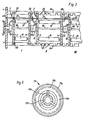
- Fig. 4 a) und b) einen Querschnitt durch eine erfindungsgemäße Antriebskupplung in vergrößertem Maßstab, einmal in geschlossenem (a) und einmal im geöffneten (b) Zustand.;
- Fig. 5 eine Seitenansicht des in den Fig. 4 a) und b) dargestellten Kupplungselementes.
- 1 shows a cross section through a treatment tank with an inserted rack.
- FIG. 2 shows a partial cross section through the rack and tank according to FIG. 1;
- 3 shows a plan view of the arrangement according to the invention of various racks in a treatment container;
- 4 a) and b) a cross section through a drive clutch according to the invention on an enlarged scale, once in the closed (a) and once in the open (b) state .;
- Fig. 5 is a side view of the coupling element shown in Fig. 4 a) and b).
In Fig. 1 ist mit 1 ein Behandlungstank einer Entwicklungsvorrichtung bezeichnet, in dem ein Einsatz 2 zur Förderung der Filme oder Filmstücke durch den Behandlungstank 1 vorgesehen ist. Der Einsatz oder das Rack 2 ist, wie vor allem aus-Fig. 2 zu ersehen ist, aus zwei Seitenwänden 3 und 4 aufgebaut, die durch nicht dargestellte Stehbolzen in bekannter Weise in einem festen Abstand voneinander gehalten werden. In den einander zugewandten Flächen der Seitenteile 3 und 4 sind sich entsprechende Führungsnuten 5 und 6 mit einer der Filmbahn entsprechenden Form ausgeformt. Die Filmbahn ist im wesentlichen U-förmige, jedoch auf der gesamten Länge der Schenkel in Form einer Schlangenlinie gekrümmt, wie dies insbesondere aus Fig. 1 deutlich wird. Am oberen Ende läuft die Nut horizontal ein, bzw. aus.In Fig. 1, 1 denotes a treatment tank of a developing device, in which an
Jeweils an den Wendepunkten der gekrümmten Filmbahn sind Förderwalzen 7 und 8 angeordnet. Die Förderwalzen 7 sind in Bohrungen der Seitenteile 3, 4 drehbar gelagert und über außerhalb des Seitenteils 3 auf der Welle der Walzen 7 sitzende Zahnräder 9 jeweils mit einem zentralen Antriebsrad 10 verbunden, das ständig mit gleichartigen Zahnrädern kämmt, so daß alle Zahnräder 9 über die Zahnräder 10 mit einem obersten Hauptantriebsrad 11 in Eingriff sind. Beim Einsetzen eines Racks 2 in den Tank 1 sind dann in bekannter Weise alle Zahnräder 9 und damit die Förderwalzen 7 an einem gemeinsamen Antrieb angeschlossen.
Die äußeren Förderwalzen 8 sind in Schlitzen 12 der Seitenteile 3, 4 in Richtung zu den entsprechenden inneren Förderwalzen 7 hin verschiebbar gelagert. Auf der Welle der Walzen 8 ist jeweils ein Rad 13 befestigt, wobei jeweils vier solche Räder 13, deren Förderwalzen 7 von einem gemeinsamen Antriebszahnrad 10 angetrieben sind, von einem elastischen, endlosen Riemen 14 umspannt werden. Durch diesen Riemen 14 werden die Walzen 8 jeweils in Kontakt gehalten mit der entsprechenden Walze 7.The
In Fig. 2 ist ferner ein Geräteantrieb 15 in Form eines Zahnrades dargestellt, das außerhalb des Behandlungsbehälters 1 angeordnet, mit einem Antriebsband verbunden und auf einer Welle 16 angebracht ist, welche durch die Tankwand führt und an der Innenseite ein Zahnrad 17 trägt. Das Zahnrad 17 kämmt mit dem Hauptantriebsrad 11 des der Antriebsseite zunächst angeordneten Racks, das doppelt breit ist und, wie oben bereits erwähnt, ebenfalls mit dem obersten Antriebsrad 10 in Eingriff steht. Das Hauptantriebsrad 11 ist auf einer Welle 18 angeordnet, die durch die beiden Seitenteile 3 und 4 geführt ist. Auf dem Hauptantriebsrad 11 kann ein Kupplungselement 19 in Form einer Bogenzahnkupplung aufgesetzt sein. Am anderen Ende der Welle 18 ist ein Gegenkupplungselement in Form eines Zahnrades 20 angeordnet, das die Form eines Schraubenzylinderkopfes aufweisen kann. Der Steg 19 eines Hauptantriebsrades kann leicht in den Schlitz 20a des Gegenkupplungselementes 20 eingesetzt werden, wie dies aus Fig. 3 zu sehen ist.FIG. 2 also shows a device drive 15 in the form of a gearwheel, which is arranged outside the
Wie ferner aus den Figuren 2 und 3 zu entnehmen ist, ist in jedem Rack ein Positionierstift 21 vorgesehen, der ebenfalls durch die beiden Seitenteile 3 und 4 geführt ist und bei eingesetztem Rack mit seinem Ende in eine Bohrung 22 mittels einer nicht dargestellten Feder eingeführt ist. Am anderen Ende des Zentrierstiftes 21 ist an diesem ein Knopf 23 angebracht, in welchem in gleicher Ausrichtung zur Bohrung 22 im Behandlungstank 1 eine Bohrung 22' vorgesehen ist. Damit kann der Zentrierstift des benachbarten Racks in Fig. 3 beispielsweise des mittleren Racks, in die Bohrung 22' im Knopf 23 des Zentrierstiftes 21 in dem der Tankwand 1 am nächsten gelegenen Rack 2 eingesetzt werden.As can also be seen from FIGS. 2 and 3, a
In Fig. 3 sind außerdem Querleisten 24 dargestellt, welche sich quer zur Transportrichtung des Filmes zwischen zwei Seitenwänden des Behandlungstanks 1 erstrecken. In den Querleisten 24 ist in gegenüberliegender Ausrichtung eine Vielzahl von Nuten 25 ausgeformt, deren Breite der Dicke der Seitenwände 3 bzw. 4 entspricht. Die Anzahl und die Abstände zur Seitenwand des Tanks 1 sind in Abhängigkeit von den gewünschten Rack-Typen festgelegt. Auf der ersten Transportbahn I können beispielsweise Racks mit sechs unterschiedlichen Breiten eingesetzt werden, wobei für das Seitenteil 3, das der Tankwand am nächsten liegt, nur eine Nut 25 vorgesehen ist, für das andere Seitenteil 4 je nach Rackbreite sechs nebeneinanderliegende Nuten 25 vorhanden sind. Dementsprechend sind auch die weiteren Nuten 25 ausgeformt, um verschiedene Kombinationen von unterschiedlichen Breiten zuzulassen.In Fig. 3
In den Fig. 4 a) und b) ist nun die Antriebskopplung aus Fig. 3 in vergrößertem Maßstab wiedergegeben. Gleiche Teile haben dabei auch gleiche Bezugszeichen. Wie in diesen Figuren zu sehen ist, ist die Antriebswelle 18 auf der das Antriebsrad 11 tragenden Seite länger ausgebildet und weist etwa die Länge eines Kupplungselementes 19 auf. Das Zahnrad 11 ist dabei etwa in der Mitte des überstehenden Wellenstückes 18a angebracht. Am äußeren Ende des Wellenstückes 18a ist eine am Mantel rundumlaufende Nut 18b ausgeformt.4 a) and b) the drive coupling from FIG. 3 is now shown on an enlarged scale. The same parts have the same reference numerals. As can be seen in these figures, the
Das Kupplungselement 19 besteht im wesentlichen aus einem zylindrischen Hülse 19a mit einer durchgehenden Innenverzahnung 19b. Außen am Zylindermantel ist eine Handhabe 19c ausgebildet. Im Inneren der Hülse 19a ist eine die Verzahnung 19b unterbrechende Ringscheibe 19d ausgebildet, von welcher Federarme 19e ausgehen, die in radialer Richtung nach innen sich erstreckende Rastvorsprünge 19f aufweisen.The
In Fig. 4 a) ist der angekoppelte Zustand zweier nebeneinanderliegender Racks dargestellt, wobei das Kupplungselement 19 mit dem kleineren Teil der Innenverzahnung auf das Abtriebsrad 20 des einen Racks aufgeschoben ist und den Antrieb Ober den größeren Teil der Innenverzahnung 19b auf das Antriebsrad 11 des nächsten Racks überträgt. In dieser Stellung rasten die Vorsprünge 19f der federnden Arme 19e in der Nut 18b des Wellenstückes 18a des nächsten Racks ein. Zum Zwecke des Endkoppelns braucht das Kupplungslement 19 lediglich in Richtung auf das nächste Rack, in Fig. 4 a) also nach rechts verschoben zu werden. Dabei kommen die Vorsprünge 19f aus dem Eingriff mit der Nut 18b und sie gleiten auf dem Umfang des Wellenstückes 18a entlang, bis das Kupplungselement an der Seitenwand 3 des nächsten Racks anstößt. Dabei wird das Kupplungselement immer noch an dem Zahnrad 11, das in der Innenverzahnung 19b läuft, geführt. Mit dieser Verschiebung wird das Abtriebsrad 20 freigegeben, womit nun eines der beiden Racks, sofern es auch auf seiner anderen Seite frei ist, dem Gerät entnommen werden kann. Zum Zwecke des Ankoppelns braucht das Kupplungselement 19 lediglich nach links über das Zahnrad 20 geschoben zu werden, solange, bis die Vorsprünge 19f in der NJt 18b einrasten.4 a) shows the coupled state of two adjacent racks, the
Im allgemeinen Betrieb wird nun stets das erste Rack in die der den Antrieb tragende Tankwand nächstliegende Mit 25 eingesetzt, wie dies mit Transportbahn I gekennzeichnet ist. Sodann wird ein Rack anderer Breite in die Transportbahn II eingesetzt, wobei das Kupplungselement 19 am Hauptantriebsrad 11 des zweiten Racks auf das Abtriebsrad 20 des ersten Racks in der oben beschriebenen Weise aufgeschoben wird. Außerdem wird der Zentrierstift 21 des zweiten Racks in die Bohrung 22' des Zentrierstiftes des ersten Racks eingeführt, womit beide Racks in ihrer Ausrichtung fixiert sind. In gleicher Weise kann ein drittes Rack auf der Transportbahn III an das zweite Rack angesetzt werden. Selbstverständlich werden in den darauffolgenden Behandlungsbehältern die Racks gleicher Breite in der gleichen Weise angeordnet. Die Entwicklung der Filme bzw. Filmstücke kann dann in bekannter Weise erfolgen.In general operation, the first rack is now always inserted into the closest 25 to the tank wall carrying the drive, as is indicated by transport path I. A rack of a different width is then inserted into the transport path II, the
Neben dem Wunsch, Filme unterschiedlicher Breite gleichzeitig in einer Entwicklungsvorrichtung behandeln zu können, kann auch der Wunsch bestehen, Filme gleicher Breite, jedoch unterschiedlicher Empfindlichkeit oder Art in einem vorhandenen Entwicklungsgerät entwickeln zu können. Bei Filmen unterschiedlicher Empfindlichkeit können aber unterschiedliche Verweilzeiten in den einzelnen Bädern vorgeschrieben sein, so daß eine Steuerung der Transportgeschwindigkeit immer nur einer Filmempfindlichkeit gerecht werden würde. Aus diesem Grunde kann die Wegstrecke durch unterschiedliche Baulängen der Racks verändert werden, um damit die für unterschiedliche Empfindlichkeiten unterschiedlichen Verweilzeiten vorzugeben.In addition to the desire to be able to treat films of different widths simultaneously in a developing device, there may also be a desire to be able to develop films of the same width but with different sensitivity or type in an existing processing device. In the case of films of different sensitivity, however, different dwell times in the individual baths may be prescribed, so that controlling the transport speed would only ever do justice to one film sensitivity. For this reason, the distance can be changed using different lengths of the racks in order to specify the different dwell times for different sensitivities.
Neben den beschriebenen Kombinationen lassen sich hinsichtlich der Verweilzeit auch noch alle anderen Rackgrößen vorsehen. Selbstverständlich können auch Racks unterschiedlicher Breite und unterschiedlicher Größe miteinander kombiniert-werden, um die unterschiedlichen Behandlungsprozesse für das jeweils anfallende Material vorsehen zu können. Mit der Erfindung lassen sich die Rack-Umrüstungen in einer Entwicklungsmaschine schnell und einfach vornehmen.In addition to the combinations described, all other rack sizes can also be provided with regard to the dwell time. Of course, racks of different widths and different sizes can also be combined with one another in order to be able to provide the different treatment processes for the respective material. With the invention, the rack conversions in a processor can be carried out quickly and easily.
Claims (6)
Applications Claiming Priority (2)
| Application Number | Priority Date | Filing Date | Title |
|---|---|---|---|
| DE19823220236 DE3220236A1 (en) | 1982-05-28 | 1982-05-28 | DEVICE FOR COUPLING THE DRIVE SHAFTS OF AT LEAST TWO ADJUSTABLE INTERCHANGEABLE TRANSPORT DEVICES IN A DEVELOPMENT MACHINE |
| DE3220236 | 1982-05-28 |
Publications (2)
| Publication Number | Publication Date |
|---|---|
| EP0096291A2 true EP0096291A2 (en) | 1983-12-21 |
| EP0096291A3 EP0096291A3 (en) | 1986-03-12 |
Family
ID=6164810
Family Applications (1)
| Application Number | Title | Priority Date | Filing Date |
|---|---|---|---|
| EP83105140A Withdrawn EP0096291A3 (en) | 1982-05-28 | 1983-05-25 | Device for coupling the shafts of at least two juxtaposed interchangeable transport systems in a developing machine |
Country Status (5)
| Country | Link |
|---|---|
| US (1) | US4514071A (en) |
| EP (1) | EP0096291A3 (en) |
| JP (1) | JPS58217824A (en) |
| DE (1) | DE3220236A1 (en) |
| DK (1) | DK159178C (en) |
Cited By (1)
| Publication number | Priority date | Publication date | Assignee | Title |
|---|---|---|---|---|
| DE19625962C1 (en) * | 1996-06-28 | 1997-11-20 | Agfa Gevaert Ag | Appliance for treating photographic emulsion carriers |
Families Citing this family (4)
| Publication number | Priority date | Publication date | Assignee | Title |
|---|---|---|---|---|
| JP3112218B2 (en) * | 1993-04-27 | 2000-11-27 | 富士写真フイルム株式会社 | Photosensitive material processing equipment |
| US8464567B2 (en) * | 2008-04-24 | 2013-06-18 | Crown Packaging Technology, Inc. | Distributed drives for a multi-stage can necking machine |
| US8245551B2 (en) | 2008-04-24 | 2012-08-21 | Crown Packaging Technology, Inc. | Adjustable transfer assembly for container manufacturing process |
| US10683900B2 (en) * | 2017-03-29 | 2020-06-16 | Pratt & Whitney Canada Corp. | Clutch device for gas turbine engines |
Citations (2)
| Publication number | Priority date | Publication date | Assignee | Title |
|---|---|---|---|---|
| US2894775A (en) * | 1952-03-20 | 1959-07-14 | Hoe & Co R | Rotary shaft clutch |
| US3672290A (en) * | 1969-10-13 | 1972-06-27 | George W Duesler | Film processing apparatus |
Family Cites Families (5)
| Publication number | Priority date | Publication date | Assignee | Title |
|---|---|---|---|---|
| US2952143A (en) * | 1958-12-01 | 1960-09-13 | Us Rubber Co | Flexible shaft couplings |
| US2918809A (en) * | 1959-02-26 | 1959-12-29 | Sier Bath Gear And Pump Co Inc | Flexible coupling for shafts |
| US3243973A (en) * | 1963-01-30 | 1966-04-05 | Drafto Corp | Flexible gear couplings |
| US3588154A (en) * | 1968-10-29 | 1971-06-28 | Bendix Corp | Torque coupling device |
| DE3119318C2 (en) * | 1981-05-15 | 1985-07-25 | Agfa-Gevaert Ag, 5090 Leverkusen | Developing device for films or pieces of film |
-
1982
- 1982-05-28 DE DE19823220236 patent/DE3220236A1/en not_active Withdrawn
-
1983
- 1983-05-12 JP JP58081846A patent/JPS58217824A/en active Granted
- 1983-05-20 US US06/496,448 patent/US4514071A/en not_active Expired - Fee Related
- 1983-05-25 EP EP83105140A patent/EP0096291A3/en not_active Withdrawn
- 1983-05-27 DK DK240383A patent/DK159178C/en active
Patent Citations (2)
| Publication number | Priority date | Publication date | Assignee | Title |
|---|---|---|---|---|
| US2894775A (en) * | 1952-03-20 | 1959-07-14 | Hoe & Co R | Rotary shaft clutch |
| US3672290A (en) * | 1969-10-13 | 1972-06-27 | George W Duesler | Film processing apparatus |
Cited By (1)
| Publication number | Priority date | Publication date | Assignee | Title |
|---|---|---|---|---|
| DE19625962C1 (en) * | 1996-06-28 | 1997-11-20 | Agfa Gevaert Ag | Appliance for treating photographic emulsion carriers |
Also Published As
| Publication number | Publication date |
|---|---|
| JPH0148540B2 (en) | 1989-10-19 |
| DK240383A (en) | 1983-11-29 |
| EP0096291A3 (en) | 1986-03-12 |
| DE3220236A1 (en) | 1983-12-01 |
| US4514071A (en) | 1985-04-30 |
| DK159178C (en) | 1991-02-11 |
| JPS58217824A (en) | 1983-12-17 |
| DK159178B (en) | 1990-09-10 |
| DK240383D0 (en) | 1983-05-27 |
Similar Documents
| Publication | Publication Date | Title |
|---|---|---|
| DE3119318C2 (en) | Developing device for films or pieces of film | |
| DE2444989A1 (en) | CONTAINER CONVEYOR | |
| DE2164215C3 (en) | Device for transporting a web-shaped edge-perforated material | |
| EP0096291A2 (en) | Device for coupling the shafts of at least two juxtaposed interchangeable transport systems in a developing machine | |
| DE3127777C2 (en) | Device for tensioning a recording medium moved by means of feed tractors | |
| DE2838964C3 (en) | Printing unit, in particular for price labeling devices | |
| DE3025465A1 (en) | DEVICE FOR CONTACTING A WIRE OR TAPE-SHAPED CARRIER WITH A CARRIER GUIDE | |
| EP0063307A2 (en) | Feeding of components | |
| DE2035157C3 (en) | Device for the continuous displacement of initially n coaxially next to one another in rod-shaped articles of the tobacco processing industry lying one after the other transversely to the longitudinal direction | |
| DE1497395C3 (en) | Self-funding development facility for pieces of film | |
| DE8215653U1 (en) | DEVICE FOR COUPLING THE DRIVE SHAFTS OF AT LEAST TWO ADJUSTABLE INTERCHANGEABLE TRANSPORT DEVICES IN A DEVELOPMENT MACHINE | |
| EP0556944A1 (en) | Printer for processing multiple types of paper and method for alternating cut paper and web feeding | |
| DE3310622C2 (en) | ||
| CH410782A (en) | Device for driving conveying elements circulating in a closed path with variable speed in individual path sections | |
| DE2714335A1 (en) | DEVICE FOR THE AUTOMATIC TREATMENT OF EXPOSED PHOTO PAPER SHEETS | |
| CH645682A5 (en) | RIETKAMMOEFFNER. | |
| DE4010330A1 (en) | Device for continuously moving and turning objects - uses endless revolving belt between inlet and outlet rollers to clamp and turn object | |
| DE2827125C2 (en) | Paper transport tractor for data printer and the like. | |
| DE1259779B (en) | Device for driving conveying organs rotating in a closed path and receiving the conveyed material | |
| DE2127705C3 (en) | Device for dividing a flow of objects into several partial flows | |
| EP0671329A1 (en) | Printing device, in particular for labelling or marking apparatus | |
| DE2307034C3 (en) | Device for assembling roller chains | |
| DE3210021A1 (en) | Machine for the cross-tying of packages or the like | |
| EP0513501A1 (en) | Method and device for treatment, in particular for testing and/or encoding, of plastic bottles or of that kind | |
| DE4115377A1 (en) | Drum counter with integral alignment for mileometer - uses sprung tooth mechanism to locate wheels in alignment |
Legal Events
| Date | Code | Title | Description |
|---|---|---|---|
| PUAI | Public reference made under article 153(3) epc to a published international application that has entered the european phase |
Free format text: ORIGINAL CODE: 0009012 |
|
| AK | Designated contracting states |
Designated state(s): CH FR GB IT LI |
|
| 17P | Request for examination filed |
Effective date: 19840920 |
|
| PUAL | Search report despatched |
Free format text: ORIGINAL CODE: 0009013 |
|
| AK | Designated contracting states |
Kind code of ref document: A3 Designated state(s): CH FR GB IT LI |
|
| STAA | Information on the status of an ep patent application or granted ep patent |
Free format text: STATUS: THE APPLICATION HAS BEEN WITHDRAWN |
|
| 18W | Application withdrawn |
Withdrawal date: 19860307 |
|
| RIN1 | Information on inventor provided before grant (corrected) |
Inventor name: SCHIRK, GUENTER Inventor name: LEHNERT, KLAUS Inventor name: KOENINGER, HORST |