EP0096026B1 - Schneidwerkzeugeinheit - Google Patents
Schneidwerkzeugeinheit Download PDFInfo
- Publication number
- EP0096026B1 EP0096026B1 EP82900103A EP82900103A EP0096026B1 EP 0096026 B1 EP0096026 B1 EP 0096026B1 EP 82900103 A EP82900103 A EP 82900103A EP 82900103 A EP82900103 A EP 82900103A EP 0096026 B1 EP0096026 B1 EP 0096026B1
- Authority
- EP
- European Patent Office
- Prior art keywords
- hub
- cutting tool
- tool unit
- shaft
- connection
- Prior art date
- Legal status (The legal status is an assumption and is not a legal conclusion. Google has not performed a legal analysis and makes no representation as to the accuracy of the status listed.)
- Expired
Links
Images

Classifications
-
- B—PERFORMING OPERATIONS; TRANSPORTING
- B23—MACHINE TOOLS; METAL-WORKING NOT OTHERWISE PROVIDED FOR
- B23P—METAL-WORKING NOT OTHERWISE PROVIDED FOR; COMBINED OPERATIONS; UNIVERSAL MACHINE TOOLS
- B23P11/00—Connecting or disconnecting metal parts or objects by metal-working techniques not otherwise provided for
- B23P11/02—Connecting or disconnecting metal parts or objects by metal-working techniques not otherwise provided for by first expanding and then shrinking or vice versa, e.g. by using pressure fluids; by making force fits
- B23P11/022—Connecting or disconnecting metal parts or objects by metal-working techniques not otherwise provided for by first expanding and then shrinking or vice versa, e.g. by using pressure fluids; by making force fits by using pressure fluids
-
- B—PERFORMING OPERATIONS; TRANSPORTING
- B26—HAND CUTTING TOOLS; CUTTING; SEVERING
- B26D—CUTTING; DETAILS COMMON TO MACHINES FOR PERFORATING, PUNCHING, CUTTING-OUT, STAMPING-OUT OR SEVERING
- B26D7/00—Details of apparatus for cutting, cutting-out, stamping-out, punching, perforating, or severing by means other than cutting
- B26D7/26—Means for mounting or adjusting the cutting member; Means for adjusting the stroke of the cutting member
- B26D7/2614—Means for mounting the cutting member
- B26D7/2621—Means for mounting the cutting member for circular cutters
Definitions
- the object of the present invention is to provide a cutting tool unit of the type mentioned at the outset which, with a compact design, enables the hub to be mounted and the cutting knife to be axially adjusted on the shaft without contamination of the surrounding machine parts - in particular the cutting knife - by the pressure medium.
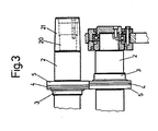
- the cutting tool unit 1 shows a partial longitudinal section of a cutting tool unit 1 with a cutting tool arranged on one of the shafts 2.
- the cutting tool unit 1 has a hub 3 which is press-fitted on the shaft 2 and to which a cutting knife 4 and a guide ring 5 are fastened.
- the ring-shaped cutting knife 4, which is preferably made of hard metal, is fastened directly on a centering seat 6 of the hub 3 by means of an adhesive, the precise round grinding of the cutting edges 7 taking place after fastening.
- the direct fastening results in a more compact design of the cutting tool unit and a higher accuracy of the concentricity and axial runout of the cutting edges 7.
- the cutting knives 4 arranged on one shaft are each directly supported by the guide rings 5 arranged on the other shaft.
Landscapes
- Engineering & Computer Science (AREA)
- Mechanical Engineering (AREA)
- Forests & Forestry (AREA)
- Life Sciences & Earth Sciences (AREA)
- Crushing And Pulverization Processes (AREA)
- Auxiliary Devices For Machine Tools (AREA)
- Processing Of Meat And Fish (AREA)
- Joining Of Corner Units Of Frames Or Wings (AREA)
- Display Devices Of Pinball Game Machines (AREA)
- Perforating, Stamping-Out Or Severing By Means Other Than Cutting (AREA)
- Treatment Of Fiber Materials (AREA)
- Scissors And Nippers (AREA)
- Details Of Cutting Devices (AREA)
- Shearing Machines (AREA)
- Accessories And Tools For Shearing Machines (AREA)
- Nonmetal Cutting Devices (AREA)
- Confectionery (AREA)
- Electrical Discharge Machining, Electrochemical Machining, And Combined Machining (AREA)
Priority Applications (1)
| Application Number | Priority Date | Filing Date | Title |
|---|---|---|---|
| AT82900103T ATE18732T1 (de) | 1981-12-17 | 1981-12-17 | Schneidwerkzeugeinheit. |
Applications Claiming Priority (1)
| Application Number | Priority Date | Filing Date | Title |
|---|---|---|---|
| PCT/EP1981/000199 WO1983002083A1 (en) | 1981-12-17 | 1981-12-17 | Cutting device |
Publications (2)
| Publication Number | Publication Date |
|---|---|
| EP0096026A1 EP0096026A1 (de) | 1983-12-21 |
| EP0096026B1 true EP0096026B1 (de) | 1986-03-26 |
Family
ID=8164836
Family Applications (1)
| Application Number | Title | Priority Date | Filing Date |
|---|---|---|---|
| EP82900103A Expired EP0096026B1 (de) | 1981-12-17 | 1981-12-17 | Schneidwerkzeugeinheit |
Country Status (7)
| Country | Link |
|---|---|
| EP (1) | EP0096026B1 (it) |
| JP (1) | JPS58502138A (it) |
| AT (1) | ATE18732T1 (it) |
| DD (1) | DD202257A5 (it) |
| DE (1) | DE3174226D1 (it) |
| IT (1) | IT1191070B (it) |
| WO (1) | WO1983002083A1 (it) |
Families Citing this family (3)
| Publication number | Priority date | Publication date | Assignee | Title |
|---|---|---|---|---|
| DE3533739A1 (de) * | 1985-09-21 | 1987-03-26 | Goebel Gmbh Maschf | Verschiebe-einrichtung |
| FR2707202B1 (fr) * | 1993-07-08 | 1995-08-18 | Komori Chambon | Dispositif d'immobilisation pour cylindre de découpe rotatif. |
| CH701086B1 (de) * | 2007-10-17 | 2010-11-30 | Jan Wernecke | Vorrichtung zur reibschlüssigen Kupplung zweier koaxialer Bauteile. |
Family Cites Families (5)
| Publication number | Priority date | Publication date | Assignee | Title |
|---|---|---|---|---|
| FR612303A (fr) * | 1926-02-19 | 1926-10-21 | Marinoni | Dispositifs de réglage pour outils circulaires de machines rotatives à travailler le papier, carton, etc. |
| US2840399A (en) * | 1952-07-26 | 1958-06-24 | Hoe & Co R | Attachment of gears to tapered shaft ends |
| US2992479A (en) * | 1958-05-14 | 1961-07-18 | Musser C Walton | Method of making equal temperature press-fit of tubular members |
| US3228102A (en) * | 1963-10-21 | 1966-01-11 | Dresser Ind | Hydraulic assembly and disassembly of parts having a heavy interference fit |
| GB1574421A (en) * | 1976-02-06 | 1980-09-10 | Metal Box Co Ltd | Method and apparatus for locating a hub on a shaft |
-
1981
- 1981-12-17 WO PCT/EP1981/000199 patent/WO1983002083A1/de not_active Ceased
- 1981-12-17 EP EP82900103A patent/EP0096026B1/de not_active Expired
- 1981-12-17 AT AT82900103T patent/ATE18732T1/de not_active IP Right Cessation
- 1981-12-17 DE DE8282900103T patent/DE3174226D1/de not_active Expired
- 1981-12-17 JP JP82500185A patent/JPS58502138A/ja active Pending
-
1982
- 1982-05-26 DD DD82240199A patent/DD202257A5/de unknown
- 1982-11-11 IT IT24169/82A patent/IT1191070B/it active
Also Published As
| Publication number | Publication date |
|---|---|
| WO1983002083A1 (en) | 1983-06-23 |
| DE3174226D1 (en) | 1986-04-30 |
| EP0096026A1 (de) | 1983-12-21 |
| IT8224169A0 (it) | 1982-11-11 |
| IT1191070B (it) | 1988-02-24 |
| IT8224169A1 (it) | 1984-05-11 |
| ATE18732T1 (de) | 1986-04-15 |
| JPS58502138A (ja) | 1983-12-15 |
| DD202257A5 (de) | 1983-09-07 |
Similar Documents
| Publication | Publication Date | Title |
|---|---|---|
| EP2874805B1 (de) | Presswalze | |
| EP2005016B1 (de) | Einbaustück zur aufnahme eines walzenzapfens | |
| DE2060207B2 (de) | Schmiermitteldichtung zum Durchschmieren der Lager eines Kreuzgelenks | |
| DE2350723C2 (de) | Dichtung für das Lager eines Walzenzapfens | |
| EP1514047A1 (de) | Drehdurchführung | |
| EP0144904A2 (de) | Lagerabdichtung für eine Zentrifuge | |
| EP0096026B1 (de) | Schneidwerkzeugeinheit | |
| EP0096083B1 (de) | Rundlaufendes Schneidwerkzeug, insbesondere zum Stranggranulieren von Kunststoffmaterial | |
| DE19815134B4 (de) | Spindelkopf für Werkzeugmaschinen | |
| DE102017113396A1 (de) | Arbeitsspindel mit Radialklemmeinrichtung | |
| EP0215404A1 (de) | Zargenführung an einer Maschine zum Stumpfschweissen von Dosenzargen | |
| EP0126232A1 (de) | Berührungsfreie Dichtung | |
| DE602005000272T2 (de) | Vorrichtung zum Schmieren eines Teils in einem Zusammenbau | |
| DE2846747B1 (de) | Praezisions-Streifenschneidmaschine | |
| DE3024585A1 (de) | Werkzeugmaschine | |
| EP0523369A1 (de) | Messerwechselvorrichtung für eine Schere zum Besäumen oder Längsteilen von Bändern | |
| EP0443505B1 (de) | Schneidvorrichtung mit Kühlwasserzufuhr zu einem Sägeblatt | |
| DE3838996A1 (de) | Radialwellendichtring | |
| DE102021118106A1 (de) | Erntevorrichtung | |
| EP0839740B1 (de) | Zellenradschleuse mit schnellwechselbarer Dichtungsanordnung | |
| EP2311568A1 (de) | Schneidsatz mit Sicherheitsdistanzringmesser | |
| EP1321180A2 (de) | Innenmischer | |
| DE2407415A1 (de) | Zapfenlager fuer schiffsschraubenwelle | |
| DE69022962T2 (de) | Bearbeitungsmaschine mit Spindel oder rotierendem Werkzeug. | |
| CH648914A5 (de) | Keilriemenscheibeneinheit fuer ein keilriemengetriebe mit veraenderlicher uebersetzung. |
Legal Events
| Date | Code | Title | Description |
|---|---|---|---|
| PUAI | Public reference made under article 153(3) epc to a published international application that has entered the european phase |
Free format text: ORIGINAL CODE: 0009012 |
|
| 17P | Request for examination filed |
Effective date: 19830812 |
|
| AK | Designated contracting states |
Kind code of ref document: A1 Designated state(s): AT BE CH DE FR GB LI LU NL SE |
|
| GRAA | (expected) grant |
Free format text: ORIGINAL CODE: 0009210 |
|
| AK | Designated contracting states |
Kind code of ref document: B1 Designated state(s): AT BE CH DE FR GB LI LU NL SE |
|
| PG25 | Lapsed in a contracting state [announced via postgrant information from national office to epo] |
Ref country code: NL Effective date: 19860326 |
|
| REF | Corresponds to: |
Ref document number: 18732 Country of ref document: AT Date of ref document: 19860415 Kind code of ref document: T |
|
| PG25 | Lapsed in a contracting state [announced via postgrant information from national office to epo] |
Ref country code: SE Effective date: 19860331 |
|
| REF | Corresponds to: |
Ref document number: 3174226 Country of ref document: DE Date of ref document: 19860430 |
|
| ET | Fr: translation filed | ||
| NLV1 | Nl: lapsed or annulled due to failure to fulfill the requirements of art. 29p and 29m of the patents act | ||
| PG25 | Lapsed in a contracting state [announced via postgrant information from national office to epo] |
Ref country code: AT Effective date: 19861217 |
|
| PG25 | Lapsed in a contracting state [announced via postgrant information from national office to epo] |
Ref country code: LU Free format text: LAPSE BECAUSE OF NON-PAYMENT OF DUE FEES Effective date: 19861231 Ref country code: LI Effective date: 19861231 Ref country code: CH Effective date: 19861231 Ref country code: BE Effective date: 19861231 |
|
| PLBE | No opposition filed within time limit |
Free format text: ORIGINAL CODE: 0009261 |
|
| STAA | Information on the status of an ep patent application or granted ep patent |
Free format text: STATUS: NO OPPOSITION FILED WITHIN TIME LIMIT |
|
| 26N | No opposition filed | ||
| BERE | Be: lapsed |
Owner name: MAWAG MASCHINENBAU A.G. Effective date: 19861231 |
|
| GBPC | Gb: european patent ceased through non-payment of renewal fee | ||
| PG25 | Lapsed in a contracting state [announced via postgrant information from national office to epo] |
Ref country code: FR Free format text: LAPSE BECAUSE OF NON-PAYMENT OF DUE FEES Effective date: 19870831 |
|
| REG | Reference to a national code |
Ref country code: CH Ref legal event code: PL |
|
| PG25 | Lapsed in a contracting state [announced via postgrant information from national office to epo] |
Ref country code: DE Effective date: 19870901 |
|
| REG | Reference to a national code |
Ref country code: FR Ref legal event code: ST |
|
| PG25 | Lapsed in a contracting state [announced via postgrant information from national office to epo] |
Ref country code: GB Free format text: LAPSE BECAUSE OF NON-PAYMENT OF DUE FEES Effective date: 19881122 |