EP0095556A2 - Device for filling bags with fluid material, especially dusty material - Google Patents
Device for filling bags with fluid material, especially dusty material Download PDFInfo
- Publication number
- EP0095556A2 EP0095556A2 EP83101449A EP83101449A EP0095556A2 EP 0095556 A2 EP0095556 A2 EP 0095556A2 EP 83101449 A EP83101449 A EP 83101449A EP 83101449 A EP83101449 A EP 83101449A EP 0095556 A2 EP0095556 A2 EP 0095556A2
- Authority
- EP
- European Patent Office
- Prior art keywords
- sack
- flaps
- edge
- filling
- bag
- Prior art date
- Legal status (The legal status is an assumption and is not a legal conclusion. Google has not performed a legal analysis and makes no representation as to the accuracy of the status listed.)
- Granted
Links
Images


Classifications
-
- B—PERFORMING OPERATIONS; TRANSPORTING
- B65—CONVEYING; PACKING; STORING; HANDLING THIN OR FILAMENTARY MATERIAL
- B65B—MACHINES, APPARATUS OR DEVICES FOR, OR METHODS OF, PACKAGING ARTICLES OR MATERIALS; UNPACKING
- B65B39/00—Nozzles, funnels or guides for introducing articles or materials into containers or wrappers
- B65B39/04—Nozzles, funnels or guides for introducing articles or materials into containers or wrappers having air-escape, or air-withdrawal, passages
-
- B—PERFORMING OPERATIONS; TRANSPORTING
- B65—CONVEYING; PACKING; STORING; HANDLING THIN OR FILAMENTARY MATERIAL
- B65B—MACHINES, APPARATUS OR DEVICES FOR, OR METHODS OF, PACKAGING ARTICLES OR MATERIALS; UNPACKING
- B65B39/00—Nozzles, funnels or guides for introducing articles or materials into containers or wrappers
- B65B39/02—Expansible or contractible nozzles, funnels, or guides
Definitions
- the present invention relates to a device for filling sacks with flowable or free-flowing, in particular dust-shaped filling material, for example for the fully automatic filling of flat and gusseted sacks made of paper, plastic or a combination of these materials, the sacks being used by means of clamping jaws to hold the lateral sack mouth areas transported to the filler neck and the bags are opened there by suction cups arranged between the jaws while simultaneously moving the jaws towards one another.
- the ratio between the outside diameter of the sleeve and the inside diameter of the bag is determined by the inflating capacity of the sleeve. If the outer diameter of the sleeve is chosen to be only slightly smaller than the inner diameter of the sack, there is a risk of the sack edge turning over when the sack is automatically pushed onto the filler neck. The bags are therefore pushed on by hand. This would largely avoid the disadvantage of the bag edge turning over. that the outside diameter of the sleeve is chosen to be considerably smaller than the inside diameter of the sack.
- From DE-OS 15 86 248 and DE-OS 24 18 228 devices are also known in which the sack is pivoted up for placement against the filler neck and the edge of the sack is held in place by expandable clamping jaws. A complete sealing of the edge of the bag is not guaranteed.
- the object of the present invention is to avoid the disadvantages of the known devices and to provide a simple mechanical, preferably fully automatic device, in which a perfect seal is produced during the filling process, so that even when filling bags with dust, with protection gas-treated or odor-laden material can be safely avoided.
- this is achieved in a device with devices for holding, transporting and opening the sack by means of expandable flaps which can be lowered into the area of the open sack edge and a telescopically displaceable surrounding the filler neck, arranged on the filler neck and sealed in the extended position, between the spreaders F ormklappen lowerable into the bag edge portion sealing pipe connection is provided at its lower end with an externally arranged Aufblähring.
- the dimensionally stable molded flaps which are preferably made from optionally surface-treated sheet metal, plastic or the like, make it possible to make the outer dimensions of the sealing connector or the inflation ring arranged on it only slightly smaller than the internal dimensions of the expanded molded flaps or the sack, so that on the one hand the largest possible filling cross-section of the filling or sealing nozzle can be realized and on the other hand a secure seal is guaranteed.
- sealing segments on the outside in the region of the sack edge, for example a firm and stable outer ring, against which the sack is pressed by the inflation ring after exposure to a pressure medium.
- sealing segments instead of placing an inflatable cuff on the sealing socket, one could also be provided on the outer ring or both on the sealing socket and on the outer ring.
- the sealing nozzle 2 which is telescopically displaceable via the actuator or the like 8, is arranged on the filling nozzle 1.
- the elastic seal 3 is arranged on the lower end of the filler neck in the form of an annular collar, and the stop ring 4 is provided on the upper end of the sealing connector, which could also be designed as an elastic seal or instead of the seal 3.
- the inflating ring which is arranged on the lower end of the sealing socket and is to be connected to a compressed air source, not shown, is designated by 5.
- the pivoted flaps 6 are provided, which are actuated via the actuator or the like 7.
- the sack 15 is held in the still closed state between the supports 14 made of elastic material which are arranged on the inner sides of the transport clamps 12 which preferably extend over most of the sack width and can be actuated by means of the actuators or the like 13.
- 11 denotes the suction cups for opening the sack 15 and 9, the suction pipe 9 which is guided through the filler neck 1 and which can be lowered and raised by means of the actuator or the like 10.
- the sack 15 clamped between the transport clamps 12 with a support 14 was here automatically transported to the filling device and in this position was transferred to the side clamps 17 (FIG. 7).
- the suction devices 11 are placed on the side wall of the bag and, after the transport clamps 12 have been opened, the suction air is switched on via the actuators or the like 13.
- An actuator or the like, not shown, moves the clamps 17 towards one another, while at the same time the suction cups 11 move away from one another and the bag 15 opens.
- the form flaps 6 have been pivoted into the sack edge region and spread apart via the actuator 7, as shown in FIG. 2, so that the sack edge region has an opening cross section corresponding to the design of the form flaps.
- the suction air for the suction cups 11 can be switched off and the sealing neck 2 can now be lowered into the area of the spread-out flaps 6, the stop ring 4 of the sealing neck 2 being pressed onto the elastic sealing ring 3 of the filler neck 1 in the lower end position and thereby filling neck 1 and sealing socket 2 are tightly connected.
- the molded flaps 6 are then moved upwards in a spread position from the edge of the sack area which is still held by the side clamps 17 and thus prevented from collapsing.
- the forming flaps emerge from the bag edge portion A is ufblähring 5 supplied with compressed air and thereby the bag 15 completely sealed from the inside.
- the outer wall of the bag is pressed against the outer segments 16 (FIG. 7) and the bag is thus additionally kept tight from the outside.
- the bag 15 is then filled with a predetermined quantity of filling material.
- the suction pipe 9 is inserted via the actuator 10 into the position shown in FIG. 4, ie into the upper edge of the sack.
- the sealing neck 2 is now raised and moved out of the bag edge area, tightened by moving apart the side clamps 17 of the bag edge area and by moving the transport clamps 12, the bag edge area of these clamped again, the elastic covering 14 of the transport clamps encloses the suction pipe 9 and hermetically seals it from the outside, so that no air can get into the sack from the outside (FIGS. 5 and 6).
- the part of the suction tube 9 which dips into the edge of the bag is, as shown in FIG. 6, preferably of oval cross-section.
- a flat, slit-shaped cross section could also be provided, or a larger number of correspondingly small, circular suction openings could be provided in the direction of the sack edge, whereby in any case overstretching of the sack material is avoided and a fold-free return of the sack edge area to an extended position is ensured.
- the vacuum feed line is closed by means of a valve (not shown) before the suction pipe 9 moves out of the sack edge area and a short compressed air pulse is used to free the suction pipe mouth from any adhering contents sent the intake manifold.
- the elastic material of the supports 14 seals the edge of the bag immediately behind the end of the suction pipe without creases, so that no air can reach the contents from the outside.
- the flaps 6 are closed, covering the cross section of the filler neck 1 in a tightly fitting manner and thus preventing that possibly trickling filling material gets into the edge of the sack between the sack walls and thereby impair the subsequent closing of the sack in a subsequent closing station or by a closing device that can be moved up to it.
- spreading elements such as wedges or the like, which can be inserted into the sack edge area above the transport clamps 12, by means of which this part of the sack edge area is spread apart and makes it possible, for example by blowing out by means of a strong compressed air pulse, to cover this area of approximately to free existing contents.
- the suction pipe 9 does not necessarily have to be arranged passing through the filler neck 1; rather, this could also be provided in a subsequent position in order to increase the performance of the device.
- the suction tube 9 can also be surrounded by a protective tube 18 which can be displaced by means of an actuator 19 and which prevents the filling material adhering to the filling material adhering to this, for example, from becoming dirty when the suction tube is pulled out, and the subsequent closing, for example by welding adversely affected.
- the transport clamps 12 do not necessarily have to be continuous, as can be seen in particular from FIG. 7, but in many cases two clamps arranged only on the side are sufficient, which do not hold the bag in its full width during transport, but only at the ends.
Abstract
Description
Die vorliegende Erfindung betrifft eine Vorrichtung zum Befüllen von Säcken mit fließ- bzw. rieselfähigem, insbesondere staubförmigem Füllgut, beispielsweise zum vollautomatischen Befüllen von Flach- und Seitenfaltensäcken aus Papier, Kunststoff oder einer Kombination dieser Werkstoffe, wobei die Säcke mittels Klemmbacken zum Halten der seitlichen Sackmündungsbereiche zum Füllstutzen transportiert und dort durch zwischen den Klemmbacken angeordnete Sauger bei gleichzeitigem Gegeneinanderbewegen der Klemmbacken die Säcke geöffnet werden.The present invention relates to a device for filling sacks with flowable or free-flowing, in particular dust-shaped filling material, for example for the fully automatic filling of flat and gusseted sacks made of paper, plastic or a combination of these materials, the sacks being used by means of clamping jaws to hold the lateral sack mouth areas transported to the filler neck and the bags are opened there by suction cups arranged between the jaws while simultaneously moving the jaws towards one another.
Zum Befüllen von Säcken kennt man Vorrichtungen, bei denen der Sack von Hand geöffnet, auf den Füllstutzen aufgesteckt und dann mittels einer mechanischen oder elektropneumatischen Sackklemme festgeklemmt und abgedichtet werden muß.Devices for filling sacks are known in which the sack has to be opened by hand, placed on the filler neck and then clamped and sealed by means of a mechanical or electro-pneumatic sack clamp.
Bekannt ist es auch, den Füllstutzen an seinem unteren Ende mit einer aufblasbaren Manschette zu versehen, die in aufgeblasenem Zustand die Öffnung zwischen dem Füllstutzen und dem auf diesen aufgeschobenen Sack abdichtet.It is also known to provide the filler neck at its lower end with an inflatable sleeve which, when inflated, seals the opening between the filler neck and the sack pushed thereon.
Das Verhältnis zwischen Manschetten-Außendurchmesser und Sack-Innendurchmesser wird dabei vom Aufblasvermögen der Manschette bestimmt. Wird der Manschetten-Außendurchmesser nur wenig kleiner gewählt als der Innendurchmesser des Sackes, so besteht bei automatischem Aufschieben des Sackes auf den Füllstutzen die Gefahr, daß der Sackrand umschlägt. Das Aufschieben der Säcke erfolgt daher von Hand. Zwar ließe sich der Nachteil des möglichen Umschlagens des Sackrandes weitgehend dadurch vermeiden. daß der Außendurchmesser der Manschette erheblich kleiner gewählt wird als der Innendurchmesser des Sackes. Eine solche Verringerung des Manschetten-Außendurchmessers hätte aber zur Folge, daß sich auch der Querschnitt des Füllstutzens entsprechend verringert und dadurch die Füllgeschwindigkeiten nachteilig beeinfluß würden, ganz abgesehen davon, daß unter Umständen ein sicherer Verschluß zwischen Manschette und Sack nicht mehr gewährleistet sein könnte.The ratio between the outside diameter of the sleeve and the inside diameter of the bag is determined by the inflating capacity of the sleeve. If the outer diameter of the sleeve is chosen to be only slightly smaller than the inner diameter of the sack, there is a risk of the sack edge turning over when the sack is automatically pushed onto the filler neck. The bags are therefore pushed on by hand. This would largely avoid the disadvantage of the bag edge turning over. that the outside diameter of the sleeve is chosen to be considerably smaller than the inside diameter of the sack. However, such a reduction in the outer diameter of the sleeve would also result in the cross-section of the filler neck accordingly reduced and thereby adversely affect the filling speeds, quite apart from the fact that under certain circumstances a secure closure between the cuff and the sack could no longer be guaranteed.
Aus der DE-GM 78 24 437 ist eine Vorrichtung bekannt, bei der eine Abdichtung zwischen Füllstutzen und Sack mittels beweglicher Platten und einem Kautschukband bewerkstelligt wird. Diese Vorrichtung ist jedoch sehr kompliziert und aufwendig.From DE-GM 78 24 437 a device is known in which a seal between the filler neck and the sack is achieved by means of movable plates and a rubber band. However, this device is very complicated and expensive.
Aus der DE-OS 15 86 248 und der DE-OS 24 18 228 kennt man auch Vorrichtungen, bei denen der Sack zum Anlegen an den Füllstutzen hochgeschwenkt und der Sackrand durch spreizbare Klemmbacken festgehalten wird. Eine völlige Abdichtung des Sackrandes ist hierbei jedoch nicht gewährleistet.From DE-OS 15 86 248 and DE-OS 24 18 228 devices are also known in which the sack is pivoted up for placement against the filler neck and the edge of the sack is held in place by expandable clamping jaws. A complete sealing of the edge of the bag is not guaranteed.
Auch bei einer aus der DE-PS 2 629 065 bekannten Vorrichtung, bei welcher Einführungsklappen in den Sackrand abgesenkt und gespreizt werden, erfolgt keine vollständige Abdichtung, so daß beim Abfüllen entsprechender Produkte die Umgebung beeinträchtigt, beispielsweise beim Abfüllen staubiger Produkte die Umgebung durch Staub verunreinigt und gegebenenfalls das Bedienungspersonal belästigt wird.Even in a device known from DE-PS 2 629 065, in which insertion flaps are lowered into the sack edge and spread, there is no complete sealing, so that when filling corresponding products the environment is impaired, for example when filling dusty products, the environment is contaminated by dust and if necessary the operating personnel is bothered.
Aufgabe der vorliegenden Erfindung ist es, die Nachteile der bekannten Vorrichtungen zu vermeiden und eine einfache mechanisch, vorzugsweise vollautomatisch arbeitende Vorrichtung zu schaffen, bei der eine einwandfreie Dichtung während des Befüllvorgangs hergestellt ist, so daß auch beim Befüllen von Säcken etwa mit staubförmigem, mit Schutzt gas behandeltem oder geruchsbehaftetem Material eine Beeinträchtigung der Umgebung sicher vermieden wird. Erfindungsgemäß wird dies bei einer Vorrichtung mit Einrichtungen zum Halten, Transportieren und öffnen des Sackes erreicht durch in den Bereich des geöffneten Sackrandes absenkbare spreizbare Formklappen sowie einen den Füllstutzen umgebenden, auf dem Füllstutzen teleskopartig verschieblich und in ausgefahrener Stellung gegenüber diesem abgedichtet angeordneten, zwischen die gespreizten Formklappen in den Sackrandbereich absenkbaren, an seinem unteren Ende mit einem außenseitig angeordneten Aufblähring versehenen Dichtstutzen.The object of the present invention is to avoid the disadvantages of the known devices and to provide a simple mechanical, preferably fully automatic device, in which a perfect seal is produced during the filling process, so that even when filling bags with dust, with protection gas-treated or odor-laden material can be safely avoided. According to the invention, this is achieved in a device with devices for holding, transporting and opening the sack by means of expandable flaps which can be lowered into the area of the open sack edge and a telescopically displaceable surrounding the filler neck, arranged on the filler neck and sealed in the extended position, between the spreaders F ormklappen lowerable into the bag edge portion sealing pipe connection is provided at its lower end with an externally arranged Aufblähring.
Anstatt die Formklappen in den Sackrandbereich abzusenken, könnte selbstverständlich auch vorgesehen sein, den Sack in entsprechender Weise anzuheben und daraufhin die Formklappen auseinanderzuspreizen. Im einen wie im anderen Falle wird durch das Einfahren der ungespreizten Formklappen in den in an sich bekannter Weise durch Klemmen gehaltenen und mittels Saugern geöffneten Sackrand sichergestellt, daß ein Umschlagen des Sackrandes nicht erfolgen kann und daß eine faltenfreie.Formgebung des Sackrandbereiches entsprechend dem Querschnitt des Füll- bzw. Dichtstutzens erzielt wird, wobei diese bevorzugt kreis- ! förmigen Querschnitt aufweisen und entsprechend die Formklappen als halbkreisförmige Schalensegmente ausgebildet werden.Instead of lowering the flaps into the edge of the sack, it could of course also be provided to raise the sack in a corresponding manner and then to spread the flaps apart. In one case as in the other, the retraction of the unspread mold flaps in the sack edge, which is held in a known manner by clamping and opened by means of suction cups, ensures that the sack edge cannot be folded over and that the sack edge area is wrinkle-free Filling or sealing nozzle is achieved, which preferably circular! have a shaped cross-section and correspondingly the flaps are designed as semicircular shell segments.
In vorteilhafter Weise ist es durch die vorzugsweise aus gegebenenfalls oberflächenbehandeltem Blech, Kunststoff oder dergleichen hergestellten formsteifen Formklappen möglich, die Außenabmessungen des Dichtstutzens bzw. des auf diesem angeordneten Aufblähringes nur wenig kleiner auszubilden als die Innenabmessungen der gespreizten Formklappen bzw. des Sackes, so daß einerseits ein größtmöglicher Befüllquerschnitt des Füll- bzw. Dichtstutzens verwirklicht werden kann und andererseits eine sichere Abdichtung gewährleistet ist.Advantageously, the dimensionally stable molded flaps, which are preferably made from optionally surface-treated sheet metal, plastic or the like, make it possible to make the outer dimensions of the sealing connector or the inflation ring arranged on it only slightly smaller than the internal dimensions of the expanded molded flaps or the sack, so that on the one hand the largest possible filling cross-section of the filling or sealing nozzle can be realized and on the other hand a secure seal is guaranteed.
Zur Verbeserung der Dichtwirkung ist in zweckmäßiger weiterer Ausbildung der Erfindung vorgesehen, im Bereich des Sackrandes außenseitige Dichtsegmente anzuordnen, beispielsweise einen festen und stabilen Außenring, gegen den durch den Aufblähring nach Beaufschlagung mit einem Druckmedium der Sack angepreßt wird. Anstatt eine aufblasbare Manschette auf dem Dichtstutzen anzuordnen, könnte eine solche auch auf dem Außenring oder sowohl auf dem Dichtstutzen als auch auf dem Außenring vorgesehen werden.In order to improve the sealing effect, in an expedient further development of the invention it is provided to arrange sealing segments on the outside in the region of the sack edge, for example a firm and stable outer ring, against which the sack is pressed by the inflation ring after exposure to a pressure medium. Instead of placing an inflatable cuff on the sealing socket, one could also be provided on the outer ring or both on the sealing socket and on the outer ring.
Weitere vorteilhafte Ausgestaltungen der Erfindung ergeben sich aus den Unteransprüchen und der folgenden Beschreibung eines in der Zeichnung schematisch dargestellten Ausführungsbeispiels. Es zeigen
Figur 1 eine Ansicht der Füllvorrichtung in der Grundstellung im Schnitt,Figur 2 eine Schnittansicht der Füllvorrichtung mit geöffnetem Sack, abgesenkten und gespreizten Formklappen,Figur 3 eine Schnittansicht der Vorrichtung in der Befüllungsposition,Figur 4 eine Schnittansicht der Vorrichtung in der Luft- absaugeposition,Figur 5 eine Seitenansicht der Klemmbacken mit eingeklemmtem Saugrohr,Figur 6 eine Draufsicht zuFigur 5,Figur 7 einen Schnitt längs der Linie A-B derFigur 3 undFigur 8 wiederum in einer Schnittansicht eine Ausführungsform mit einem das Saugrohr umgebenden Schutzrohr.
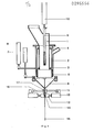
- FIG. 1 is a sectional view of the filling device in the basic position,
- FIG. 2 shows a sectional view of the filling device with the bag open, the mold flaps lowered and spread,
- FIG. 3 shows a sectional view of the device in the filling position,
- FIG. 4 shows a sectional view of the device in the air suction position,
- FIG. 5 shows a side view of the clamping jaws with the suction tube clamped,
- FIG. 6 shows a top view of FIG. 5,
- 7 shows a section along the line AB of Figure 3 and
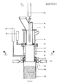
- FIG. 8 again shows a sectional view of an embodiment with a protective tube surrounding the suction tube.
Nach Figur 1 ist auf dem Füllstutzen 1 der über das Stellglied oder dergleichen 8 teleskopartig verschieblich angeordnete Dichtstutzen 2 angeordnet. Am ringbundförmig ausgebildeten unteren Ende des Füllstutzens ist die elastische Dichtung 3 angeordnet und am oberen Ende des Dichtstutzens ist der Anschlagring 4 vorgesehen, der ebenfalls oder anstatt der Dichtung 3 als elastische Dichtung ausgebildet sein könnte. Mit 5 ist der auf dem unteren Ende des Dichtstutzens angeordnete Aufblähring bezeichnet, der an eine nicht gezeigte Druckluftquelle angeschlossen sein soll. Unterhalb des Füllstutzens sind die schwenkbar angeordneten Formklappen 6 vorgesehen, deren Betätigung über das Stellglied oder dergleichen 7 erfolgt. Der Sack 15 ist in noch geschlossenem Zustand zwischen den an den Innenseiten der vorzugsweise über den größten Teil der Sackbreite reichenden und mittels der Stellglieder oder 1 dergleichen 13 betätigbaren Transportklemmen 12 angeordneten Auflagen 14 aus elastischem Werkstoff gehalten. 11 bezeichnet die Sauger zum öffnen des Sackes 15 und 9 das durch den Füllstutzen 1 hindurchgeführte und mittels des Stellgliedes oder dergleichen 10 absenkbar und anhebbar angeordnete Saugrohr 9.According to FIG. 1, the sealing
Der zwischen den Transportklemmen 12 mit Auflage 14 eingeklemmte Sack 15 sei hier automatisch zur Füllvorrichtung transportiert worden und in dieser Position an die seit- lichen Klemmen 17 (Figur 7) übergeben worden. Mit dem Schließen der Klemmen 17 werden die Sauger 11 an die Sackseitenwand angelegt und nach dem öffnen der Transportklemmen 12 über die Stellglieder oder dergleichen 13 die Saugluft eingeschaltet. Ein nicht dargestelltes Stellglied oder dergleichen bewegt die Klemmen 17 aufeinander zu, während sich in entsprechender Weise gleichzeitig die Sauger 11 voneinander entfernen und den Sack 15 öffnen.The
In den so geöffneten Sack 15 sind über das Stellglied 7, wie in Figur 2 gezeigt, die Formklappen 6 in den Sackrandbereich eingeschwenkt und auseinandergespreizt worden, so daß der Sackrandbereich einen der Ausbildung der Formklappen entsprechenden öffnungsquerschnitt aufweist. In diesem Stadium kann die Saugluft für die Sauger 11 abgeschaltet und nunmehr der Dichtstutzen 2 in den Bereich der gespreizten Formklappen 6 abgesenkt werden, wobei in der unteren Endstellung der Anschlagring 4 des Dichtstutzens 2 auf den elastischen Dichtring 3 des Füllstutzens 1 gepreßt wird und dadurch Füllstutzen 1 und Dichtstutzen 2 dicht miteinander verbunden sind.In the
Wie in Figur 3 gezeigt werden daraufhin die Formklappen 6 in gespreizter Position aus dem durch die Seitenklemmen 17 nach wie vor gehaltenen und damit am Zusammenfallen verhinderten Sackrandbereich nach oben herausgefahren. Sobald die Formklappen aus dem Sackrandbereich austreten, wird der Aufblähring 5 mit Druckluft beaufschlagt und dadurch der Sack 15 von innen her völlig abgedichtet. Gleichzeitig wird die Sackaußenwand an die Außensegmente 16 gepreßt (Figur 7) und damit der Sack zusätzlich von außen dicht gehalten. Im Anschluß daran erfolgt die Befüllung des Sackes 15 mit einer vorher festgelegten Füllgutmenge.As shown in FIG. 3, the molded
Nach Beendigung des Füllvorganges wird das Saugrohr 9 über das Stellglied 10 in die in Figur 4 gezeigte Position, d.h. in den oberen Sackrandbereich eingeführt. Durch das Stellglied 8 wird nunmehr der Dichtstutzen 2 angehoben und aus dem Sackrandbereich herausgefahren, durch Auseinanderfahren der Seitenkklemmen 17 der Sackrandbereich gestrafft und durch Zusammenfahren der Transportklemmen 12 der Sackrandbereich von diesen wieder eingeklemmt, wobei der elastische Belag 14 der Transportklemmen das Saugrohr 9 umschließt und nach außen hermetisch abdichtet, so daß von außen keine Luft mehr in den Sack gelangen kann (Figuren 5 und 6). Der in den Sackrandbereich eintauchende Teil des Saugrohrs 9 ist, wie in Figur 6 gezeigt, vorzugsweise mit ovalem Querschnitt ausgebildet. Anstelle dessen könnte selbstverständlich aber auch ein flacher schlitzförmiger Querschnitt vorgesehen werden oder es könnten in Richtung des Sackrandes hintereinander eine größere Anzahl von entsprechend kleinen kreisrunden Saugöffnungen vorgesehen werden, wobei in jedem Falle eine überdehnung des Sackmaterials vermieden und eine faltenfreie Rückführung des Sackrandbereiches in eine gestreckte Position sichergestellt ist. Im Falle des Befüllens mit staubförmigem Füllgut empfiehlt es sich, wie in Figur 5 angedeutet, am unteren Ende des Saugrohres 9 ein Sieb, einen Filter oder dergleichen vorzusehen.After the filling process has been completed, the
Nachdem während einer einstellbaren Zeit die im oberen Teil des Sackes 15 eingeschlossene Luft abgesaugt ist, wird vor dem Herausfahren des Saugrohrs 9 aus dem Sackrandbereich die Vakuumzuleitung mittels eines nicht dargestellten Ventils verschlossen und zwecks Befreiung der Saug- rohrmündung von eventuell anhaftendem Füllgut ein kurzer Druckluftimpuls durch das Saugrohr geschickt.After the air enclosed in the upper part of the
Schon während das Saugrohr 9 den Bereich der Transportklemme 12 verläßt, dichtet der elastische Werkstoff der Auflagen 14 den Sackrand unmittelbar hinter dem Saugrohrende faltenfrei ab, so daß von außen keine Luft mehr an das Füllgut gelangen kann. Ist das Saugrohr in seiner oberen Endstellung angelangt bzw. genügend weit aus dem Sackrandbereich herausgefahren, werden die Formklappen 6 geschlossen, wobei sie den Querschnitt des Füllstutzens 1 miteinander dicht schließend überdecken und somit verhindern, daß eventuell nachrieselndes Füllgut zwischen die Sackwände in den Sackrandbereich gelangt und dadurch das nachfolgende Verschließen des Sackes in einer nachgeschalteten Verschließstation oder aber durch eine heranfahrbare Verschließeinrichtung beeinträchtigen. In diesem Sinne kann es sich auch als zweckmäßig erweisen, in den Sackrandbereich oberhalb der Transportklemmen 12 einfahrbare Spreizelemente wie Keile oder dergleichen vorzusehen, durch welche dieser Teil des Sackrandbereiches auseinandergespreizt und es ermöglicht wird, etwa durch Ausblasen mittels eines kräftigen Druckluftimpulses, diesen Bereich von etwa vorhandenem Füllgut zu befreien.Already while the
Es versteht sich, daß die erfindungsgemäße Vorrichtung in vielerlei Weise verändert werden kann, ohne dabei vom Erfindungsgedanken abzuweichen. So braucht zum Beispiel das Saugrohr 9 nicht notwendigerweise durch den Füllstutzen 1 hindurchgehend angeordnet werden, vielmehr könnte dieses zwecks eventueller Leistungssteigerung der Vorrichtung auch in einer nachfolgenden Position vorgesehen werden. Wie in Figur 8 gezeigt, kann das Saugrohr 9 auch mit einem mittels eines Stellgliedes 19 verschiebbaren Schutzrohr 18 umgeben werden, welches verhindert, daß beim Herausfahren des Saugrohres etwa an diesem anhaftendes Füllgut die Sackinnenwand im Bereich des Sackrandes verschmutzt und das anschließende Verschließen etwa durch Verschweißen nachteilig beeinflußt.It goes without saying that the device according to the invention can be changed in many ways without deviating from the inventive concept. For example, the
Anstatt nur eines einzigen Saugrohres könnten auch deren mehrere in entsprechend günstiger Anordnung vorgesehen werden und ebenso könnte beispielsweise auch das Formen des Sackrandbereiches mittels der Formklappen 6 schon zu einem früheren Zeitpunkt, etwa während der Zuführung des Sackes 15 zur Befüllstation, und gegebenenfalls an anderer Stelle, erfolgen.Instead of just a single suction tube, several of them could also be provided in a correspondingly favorable arrangement, and likewise, for example, the shaping of the sack edge region by means of the
Wie schon erwähnt ist auch die Umkehrung mancher Bewegungsabläufe vorstellbar oder auch die Verwendung anderer entsprechende bekannter technischer Elemente zur Herbeifüh- rung des beabsichtigten Zweckes im Rahmen der Erfindung denkbar.As already mentioned, the reversal of some movement sequences is also conceivable, or the use of other corresponding known technical elements to achieve the intended purpose is also conceivable within the scope of the invention.
So müssen die Transportklemmen 12 nicht unbedingt durchgehend sein, wie insbesondere aus Figur 7 ersichtlich, sondern es genügen in vielen Fällen zwei nur seitlich angeordnete Klemmen, die den Sack beim Transport nicht in der vollen Breite, sondern nur an den Enden halten.Thus, the transport clamps 12 do not necessarily have to be continuous, as can be seen in particular from FIG. 7, but in many cases two clamps arranged only on the side are sufficient, which do not hold the bag in its full width during transport, but only at the ends.
Claims (8)
Applications Claiming Priority (2)
| Application Number | Priority Date | Filing Date | Title |
|---|---|---|---|
| DE19823220780 DE3220780A1 (en) | 1982-06-02 | 1982-06-02 | DEVICE FOR FILLING BAGS WITH FLOW OR GIANT-SHAPED, PARTICULARLY DUST-SHAPED FILLING MATERIAL |
| DE3220780 | 1982-06-02 |
Publications (3)
| Publication Number | Publication Date |
|---|---|
| EP0095556A2 true EP0095556A2 (en) | 1983-12-07 |
| EP0095556A3 EP0095556A3 (en) | 1985-03-27 |
| EP0095556B1 EP0095556B1 (en) | 1987-01-14 |
Family
ID=6165112
Family Applications (1)
| Application Number | Title | Priority Date | Filing Date |
|---|---|---|---|
| EP83101449A Expired EP0095556B1 (en) | 1982-06-02 | 1983-02-16 | Device for filling bags with fluid material, especially dusty material |
Country Status (2)
| Country | Link |
|---|---|
| EP (1) | EP0095556B1 (en) |
| DE (2) | DE3220780A1 (en) |
Cited By (7)
| Publication number | Priority date | Publication date | Assignee | Title |
|---|---|---|---|---|
| FR2604971A1 (en) * | 1986-10-14 | 1988-04-15 | Haver & Boecker | DEVICE FOR FILLING AND CLOSING OPEN BAGS |
| EP0339627A1 (en) * | 1988-04-28 | 1989-11-02 | "FIX" PETER STEIMEL GMBH & CO.KG | Method and device for filling plastic bags |
| FR2734788A1 (en) * | 1995-06-01 | 1996-12-06 | Ridolfi Carlo | Automatic handler for bags filled in packing machine |
| EP2014579A1 (en) * | 2005-03-15 | 2009-01-14 | Nordenia Deutschland Emsdetten GmbH | Device for filling a flexible container |
| US9114898B2 (en) | 2011-03-02 | 2015-08-25 | Haver & Boecker Ohg | Apparatus and method for filling valve bags with dry bulk materials |
| CN105819028A (en) * | 2016-06-07 | 2016-08-03 | 南通恒力医药设备有限公司 | Deformable funnel for particle material filling |
| EP3416889A4 (en) * | 2016-02-17 | 2019-08-14 | Panpac Engineering A/S | Method for adjustment of system for filling of big bags, and system for filling of big bags |
Families Citing this family (5)
| Publication number | Priority date | Publication date | Assignee | Title |
|---|---|---|---|---|
| DE3427394A1 (en) * | 1984-07-25 | 1986-02-06 | Haver & Boecker, 4740 Oelde | Device for filling open bags |
| DE3618981A1 (en) * | 1985-07-04 | 1987-01-15 | Duerbeck Papiersackfab | Apparatus for the filling of valve bags |
| DE3726137A1 (en) * | 1987-08-06 | 1989-02-16 | Haver & Boecker | DEVICE FOR FILLING OPEN BAGS FROM ABOVE |
| DE19934148A1 (en) * | 1999-07-26 | 2001-02-01 | Neuhaeuser Gmbh Umwelt Dosier | Device for forming gas-tight seal between hopper and container which is being filled with liquid or bulk material comprises trough which surrounds hopper outlet and is filled with liquid and into which sealing lip fitted to hopper dips |
| DE10247291A1 (en) * | 2002-10-10 | 2004-04-22 | Weber-Waagenbau und Wägeelektronik GmbH | Filling station for bag formation and filling machine has filler socket with filler tube moved into neck of bag and swelling seal |
Citations (5)
| Publication number | Priority date | Publication date | Assignee | Title |
|---|---|---|---|---|
| CH308711A (en) * | 1951-10-02 | 1955-07-31 | Continental Can Co | Device for filling foldable containers. |
| CH376045A (en) * | 1959-01-24 | 1964-03-15 | Roller Erwin | Pneumatically acting holding device for tubular packaging such as bags, sacks and the like |
| FR2183252A1 (en) * | 1972-04-26 | 1973-12-14 | Librawerk Pelz & Nagel Kg | |
| US3830266A (en) * | 1973-03-23 | 1974-08-20 | Okinkraft Inc | Drop-down fill spout for bag filling machine |
| US4322932A (en) * | 1980-05-05 | 1982-04-06 | Mcgregor Harold R | Bag filling and handling apparatus |
-
1982
- 1982-06-02 DE DE19823220780 patent/DE3220780A1/en not_active Withdrawn
-
1983
- 1983-02-16 DE DE8383101449T patent/DE3369103D1/en not_active Expired
- 1983-02-16 EP EP83101449A patent/EP0095556B1/en not_active Expired
Patent Citations (5)
| Publication number | Priority date | Publication date | Assignee | Title |
|---|---|---|---|---|
| CH308711A (en) * | 1951-10-02 | 1955-07-31 | Continental Can Co | Device for filling foldable containers. |
| CH376045A (en) * | 1959-01-24 | 1964-03-15 | Roller Erwin | Pneumatically acting holding device for tubular packaging such as bags, sacks and the like |
| FR2183252A1 (en) * | 1972-04-26 | 1973-12-14 | Librawerk Pelz & Nagel Kg | |
| US3830266A (en) * | 1973-03-23 | 1974-08-20 | Okinkraft Inc | Drop-down fill spout for bag filling machine |
| US4322932A (en) * | 1980-05-05 | 1982-04-06 | Mcgregor Harold R | Bag filling and handling apparatus |
Cited By (8)
| Publication number | Priority date | Publication date | Assignee | Title |
|---|---|---|---|---|
| FR2604971A1 (en) * | 1986-10-14 | 1988-04-15 | Haver & Boecker | DEVICE FOR FILLING AND CLOSING OPEN BAGS |
| EP0339627A1 (en) * | 1988-04-28 | 1989-11-02 | "FIX" PETER STEIMEL GMBH & CO.KG | Method and device for filling plastic bags |
| FR2734788A1 (en) * | 1995-06-01 | 1996-12-06 | Ridolfi Carlo | Automatic handler for bags filled in packing machine |
| EP2014579A1 (en) * | 2005-03-15 | 2009-01-14 | Nordenia Deutschland Emsdetten GmbH | Device for filling a flexible container |
| US9114898B2 (en) | 2011-03-02 | 2015-08-25 | Haver & Boecker Ohg | Apparatus and method for filling valve bags with dry bulk materials |
| EP3416889A4 (en) * | 2016-02-17 | 2019-08-14 | Panpac Engineering A/S | Method for adjustment of system for filling of big bags, and system for filling of big bags |
| US11267592B2 (en) | 2016-02-17 | 2022-03-08 | Panpac Engineering A/S | Method for adjustment of system for filling of big bags, and system for filling of big bags |
| CN105819028A (en) * | 2016-06-07 | 2016-08-03 | 南通恒力医药设备有限公司 | Deformable funnel for particle material filling |
Also Published As
| Publication number | Publication date |
|---|---|
| DE3369103D1 (en) | 1987-02-19 |
| EP0095556A3 (en) | 1985-03-27 |
| EP0095556B1 (en) | 1987-01-14 |
| DE3220780A1 (en) | 1983-12-08 |
Similar Documents
| Publication | Publication Date | Title |
|---|---|---|
| DE2007747C3 (en) | Method and apparatus for inflating a tubeless tire mounted on a wheel rim | |
| EP0095556B1 (en) | Device for filling bags with fluid material, especially dusty material | |
| DE2301817B2 (en) | DEVICE FOR MANUFACTURING, OPENING, FILLING AND CLOSING SIDE GOLD BAGS | |
| EP0082955B1 (en) | Device for filling bags | |
| DE2947872A1 (en) | BAGING DEVICE | |
| EP1689643A1 (en) | Continuously operating vertical bag forming, filling and sealing machine | |
| EP0726202A1 (en) | Machine for making flat bags | |
| AT406252B (en) | DEVICE FOR FILLING AND SEALING OPEN BAGS | |
| EP0111101B1 (en) | Sack filling device | |
| EP3826831B1 (en) | Device and method for producing at least one empty open bag | |
| DE3814337C2 (en) | ||
| DE3618981C2 (en) | ||
| WO2008116638A1 (en) | Multifunctional sealing element | |
| DE2402589C3 (en) | Device with stations arranged on a circumference for the production of gusseted sacks from a gusseted tube | |
| DE3700345C2 (en) | ||
| DE2154777B2 (en) | Device for reinforcing the filling and filling neck of a hollow body made of plastic | |
| DE2058652A1 (en) | Method and device for removing air from a valve bag | |
| DE2214164A1 (en) | DEVICE FOR CREATING AND FILLING AN OPEN-UP BAG OD. DGL | |
| DE1940783B1 (en) | Device for wrapping stacks, in particular stacks of bricks, by means of a film tube | |
| DE3441947A1 (en) | Method and apparatus for opening a flat bag | |
| EP1145999A1 (en) | Device for filling a container, container and lid therefor | |
| EP1232850A2 (en) | Process and apparatus for shaping and/or sealing of a packaging unit | |
| DE3834524A1 (en) | DEVICE FOR THE VACUUM PACKAGING OF ITEMS IN FLEXIBLE BAGS OR SLEEVES | |
| DE3039751C2 (en) | Method for filling loose material, in particular powder, into a container made of flexible material and device for carrying out the method | |
| EP0105207B1 (en) | Dust protecting device |
Legal Events
| Date | Code | Title | Description |
|---|---|---|---|
| PUAI | Public reference made under article 153(3) epc to a published international application that has entered the european phase |
Free format text: ORIGINAL CODE: 0009012 |
|
| AK | Designated contracting states |
Designated state(s): DE FR GB IT |
|
| PUAL | Search report despatched |
Free format text: ORIGINAL CODE: 0009013 |
|
| AK | Designated contracting states |
Designated state(s): DE FR GB IT |
|
| 17P | Request for examination filed |
Effective date: 19850801 |
|
| GRAA | (expected) grant |
Free format text: ORIGINAL CODE: 0009210 |
|
| AK | Designated contracting states |
Kind code of ref document: B1 Designated state(s): DE FR GB IT |
|
| ITF | It: translation for a ep patent filed |
Owner name: ING. C. GREGORJ S.P.A. |
|
| REF | Corresponds to: |
Ref document number: 3369103 Country of ref document: DE Date of ref document: 19870219 |
|
| ET | Fr: translation filed | ||
| PLBE | No opposition filed within time limit |
Free format text: ORIGINAL CODE: 0009261 |
|
| STAA | Information on the status of an ep patent application or granted ep patent |
Free format text: STATUS: NO OPPOSITION FILED WITHIN TIME LIMIT |
|
| 26N | No opposition filed | ||
| PG25 | Lapsed in a contracting state [announced via postgrant information from national office to epo] |
Ref country code: GB Effective date: 19890216 |
|
| GBPC | Gb: european patent ceased through non-payment of renewal fee | ||
| PG25 | Lapsed in a contracting state [announced via postgrant information from national office to epo] |
Ref country code: FR Free format text: LAPSE BECAUSE OF NON-PAYMENT OF DUE FEES Effective date: 19891027 |
|
| REG | Reference to a national code |
Ref country code: FR Ref legal event code: ST |
|
| PGFP | Annual fee paid to national office [announced via postgrant information from national office to epo] |
Ref country code: DE Payment date: 19900126 Year of fee payment: 8 |
|
| PG25 | Lapsed in a contracting state [announced via postgrant information from national office to epo] |
Ref country code: DE Effective date: 19911101 |