EP0094928A2 - Discharging device for a shaft furnace - Google Patents
Discharging device for a shaft furnace Download PDFInfo
- Publication number
- EP0094928A2 EP0094928A2 EP83890059A EP83890059A EP0094928A2 EP 0094928 A2 EP0094928 A2 EP 0094928A2 EP 83890059 A EP83890059 A EP 83890059A EP 83890059 A EP83890059 A EP 83890059A EP 0094928 A2 EP0094928 A2 EP 0094928A2
- Authority
- EP
- European Patent Office
- Prior art keywords
- lock chamber
- cellular wheel
- discharge device
- wheel
- furnace
- Prior art date
- Legal status (The legal status is an assumption and is not a legal conclusion. Google has not performed a legal analysis and makes no representation as to the accuracy of the status listed.)
- Granted
Links
Images


Classifications
-
- F—MECHANICAL ENGINEERING; LIGHTING; HEATING; WEAPONS; BLASTING
- F27—FURNACES; KILNS; OVENS; RETORTS
- F27B—FURNACES, KILNS, OVENS, OR RETORTS IN GENERAL; OPEN SINTERING OR LIKE APPARATUS
- F27B1/00—Shaft or like vertical or substantially vertical furnaces
- F27B1/10—Details, accessories, or equipment peculiar to furnaces of these types
- F27B1/21—Arrangements of devices for discharging
-
- C—CHEMISTRY; METALLURGY
- C21—METALLURGY OF IRON
- C21B—MANUFACTURE OF IRON OR STEEL
- C21B13/00—Making spongy iron or liquid steel, by direct processes
- C21B13/02—Making spongy iron or liquid steel, by direct processes in shaft furnaces
Abstract
Eine Austragungsvorrichtung für einen Schachtofen besteht aus einer mittels einer Förderleitung (1) mit dem Schachtofen verbundenen Schleusenkammer (2), in der ein das Ofengut aufnehmender, den Schleusenkammereinlaß (28) vom Schleusenkammerauslaß (29) abschließender Rotor antreibbar gelagert ist. Um einen kontinuierlichen Gutaustrag ohne Austrittsgefahr von Ofengas sicherzustellen, besteht der Rotor aus einem Zellenrad (3) mit sternförmig angeordneten Zellenwänden (6), wobei die Förderleitung (1) an eine Sperrgas-Druckquelle angeschlossen ist und die Schleusenkammer (2) zwischen dem Schleusenkammereinlaß (28) und dem Schleusenkammerauslaß (29) eine Abgasleitung (30) im Förderbereich des Zellenrades (3) aufweist.A discharge device for a shaft furnace consists of a lock chamber (2) connected to the shaft furnace by means of a delivery line (1), in which a rotor receiving the furnace material and closing the lock chamber inlet (28) from the lock chamber outlet (29) is drivably mounted. In order to ensure continuous discharge of material without the risk of furnace gas escaping, the rotor consists of a cell wheel (3) with star-shaped cell walls (6), the delivery line (1) being connected to a sealing gas pressure source and the lock chamber (2) between the lock chamber inlet ( 28) and the lock chamber outlet (29) has an exhaust pipe (30) in the delivery area of the cellular wheel (3).
Description
Die Erfindung bezieht sich auf eine Austragungsvorrichtung für einen Schachtofen, bestehend aus einer mittels einer Forderleitung mit dem Schachtofen verbundenen Schleusenkammer, in der ein das Ofengut aufnehmender, den Schleusenkammereinlaß vom Schleusenkammerauslaß abschließender Rotor antreibbar gelagert ist.The invention relates to a discharge device for a shaft furnace, consisting of a lock chamber connected to the shaft furnace by means of a delivery line, in which a rotor receiving the furnace material and closing the lock chamber inlet from the lock chamber outlet is drivably mounted.
Um eine unerwünschte Oxidation zu vermeiden und weitgehend frei von Staubbelästigungen zu bleiben, wird der in einem Schachtofen reduzierte Eisenschwamm heiß ausgetragen und brikettiert. Dabei ergibt sich allerdings die Schwierigkeit, den Austritt des unter Druck stehenden Ofengases aus dem Ofen zu verhindern. Zu diesem Zweck ist es bekannt, das Ofengut portionsweise mit Hilfe eines an die Austragsöffnung ansetzbaren Behälters auszutragen,so daß die Austragsöffnung nach dem Gutaustrag wieder verschlossen werden kann.In order to avoid undesired oxidation and to remain largely free of dust, the iron sponge reduced in a shaft furnace is discharged hot and briquetted. However, there is a difficulty in preventing the furnace gas under pressure from escaping from the furnace. For this purpose, it is known to discharge the kiln goods in portions with the aid of a container which can be attached to the discharge opening, so that the discharge opening can be closed again after the discharge.
Bei anderen bekannten Austragungsvorrichtungen (DE-PSen 337 622, 338 413 und 345 027) sind über eine Förderleitung mit dem Schachtofen verbundene Schleusenkammern vorgesehen, in denen ein aus einer Trommel bestehender Rotor drehbar gelagert ist. Diese Trommel weist dabei in einem Umfangsbereich eine Durchtrittsöffnung zur Aufnahme bzw. zur Abgabe des Ofengutes auf. Stimmt die Durchtrittsöffnung der Trommel mit dem Schleusenkammereinlaß überein, so wird Gut aus dem Schachtofen in die Trommel eingebracht. Bei einer Drehung der Trommel wird der Schleusenkammereinlaß durch den Trommelmantel abgeschlossen und der Schleusenkammerauslaß geöffnet, wenn die Durchtrittsöffnung im Trommelmantel in den Bereich des Schleusenkammerauslasses gelangt, wobei das Ofengut aus der Trommel durch den Schleusenkammerauslaß abfallen kann. Nachteilig bei dieser Anordnung einer Trommel ist vor allem, daß das Ofengut nicht kontinuierlich durch die Schleusenkammer gefördert werden kann und daß keine Sicherheit vor einem unerwünschten Austreten von Ofengas durch die Schleusenkammer gegeben ist. Dazu kommt noch, daß mit der Drehung der Trommel keine Gutförderung zwischen dem Schleusenkammerein- und -auslaß verbunden ist, weil das Ofengut entweder mit der Trommel mitgedreht wird oder sich an der Trommelinnenwand abwälzt.In other known discharge devices (DE-PS 337 622, 338 413 and 345 027) lock chambers are provided via a delivery line connected to the shaft furnace, in which a rotor consisting of a drum is rotatably mounted. This drum has a passage opening in a circumferential area for receiving or delivering the furnace material. If the passage opening of the drum matches the lock chamber inlet, material is brought into the drum from the shaft furnace. When the drum rotates, the lock chamber inlet is closed by the drum jacket and the lock chamber outlet is opened when the passage opening in the drum jacket reaches the area of the lock chamber outlet, and the furnace material can fall out of the drum through the lock chamber outlet. The main disadvantage of this arrangement of a drum is that the furnace material cannot be conveyed continuously through the lock chamber and that there is no security against undesired escape of furnace gas through the lock chamber. In addition, the rotation of the drum means that no material is conveyed between the lock chamber inlet and outlet, because the furnace material is either rotated with the drum or rolls on the inside wall of the drum.
Der Erfindung liegt somit die Aufgabe zugrunde, diese Mängel zu vermeiden und eine äustragungvorrichtung der eingangs geschilderten Art so zu verbessern, daß ein kontinuierlicher Gutaustrag mit einer vergleichsweise hohen Durchsatzleistung sichergestellt wird, und zwar ohne Gefahr eines Austretens von Ofengas.The invention is therefore based on the object of avoiding these deficiencies and improving a discharge device of the type described at the outset in such a way that a continuous discharge of material is ensured with a comparatively high throughput capacity, without the risk of furnace gas escaping.
Die Erfindung löst die gestellte Aufgabe dadurch, daß der Rotor aus einem Zellenrad mit sternförmig angeordneten Zellenwänden besteht, daß die Förderleitung an eine Sperrgas-Druckquelle angeschlossen ist und daß die Schleusenkammer zwischen dem Schleusenkammereinlaß und dem Schleusenkammerauslaß eine Abgasleitung im FÖrderbereich des Zellenrades aufweist.The invention solves this problem in that the rotor consists of a cellular wheel with star-shaped cell walls, that the delivery line is connected to a sealing gas pressure source and that Lock chamber between the lock chamber inlet and the lock chamber outlet has an exhaust pipe in the delivery area of the cellular wheel.
Durch das Vorsehen eines Zellenrades wird eine einfach aufgebaute, kontinuierlich arbeitende Druckschleuse erhalten, ohne einen Druckverlust im Ofen in Kauf nehmen zu müssen. Das in die Förderleitung zwischen der Fördereinrichtung und der Schleusenkammer eingeleitete Sperrgas, das zumindest einen dem Druck des Ofengases entsprechenden Druck aufweisen muß, verhindert dabei, daß Ofengas bis zur Schleusenkammer vordringen kann. Um zu verhindern, daß mit dem Ofengut größere Sperrgasmengen durch die Schleusenkammer ausgetragen werden, ist die Schleusenkammer zwischen dem Schleusenkammereinlaß und dem Schleusenkammerauslaß im Förderbereich des Zellenrades an eine Abgasleitung angeschlossen, über die das in die Schleusenkammer eindringende Sperrgas abgeführt werden kann.By providing a cellular wheel, a simply constructed, continuously operating pressure lock is obtained without having to accept pressure loss in the furnace. The sealing gas introduced into the delivery line between the delivery device and the lock chamber, which must have at least a pressure corresponding to the pressure of the furnace gas, prevents furnace gas from penetrating as far as the lock chamber. In order to prevent larger amounts of sealing gas from being discharged through the lock chamber with the kiln goods, the lock chamber between the lock chamber inlet and the lock chamber outlet in the delivery area of the cellular wheel is connected to an exhaust gas line, via which the sealing gas entering the lock chamber can be discharged.
Der notwendige Druckabbau in der Schleusenkammer beruht darauf, daß die Zellenwände an die Umfangwand der Schleusenkammer anschließen und einen Verschluß zwischen dem Schleusenkammereinlaß und dem Schleusenkammerauslaß bilden. Da dieser Verschluß jedoch wegen des notwendigen Spieles zwischen dem Zellenrad und der Schleusenkammer nicht völlig gasdicht sein kann, wird das Sperrgas auch entgegen der Förderrichtung des Zellen-. rades zwischen den Zellenwänden des Zellenrades und der Schleusenkammerwandung in die Schleusenkammer eindringen. Um auch diesen Sperrgasanteil am Austritt aus der Schleusenkammer zu hindern, kann an die Schleusenkammer zwischen dem Schleusenkammereinlaß und dem Schleusenkammerauslaß im Rücklaufbereich des Zellenrades ebenfalls eine Abgasleitung angeschlossen werden.The necessary pressure reduction in the lock chamber is based on the fact that the cell walls connect to the peripheral wall of the lock chamber and form a seal between the lock chamber inlet and the lock chamber outlet. Since this closure, however, cannot be completely gas-tight because of the necessary play between the cell wheel and the lock chamber, the sealing gas is also counter to the conveying direction of the cell. Rades penetrate into the lock chamber between the cell walls of the feeder and the lock chamber wall. In order to prevent this sealing gas component from escaping from the lock chamber, an exhaust pipe can also be connected to the lock chamber between the lock chamber inlet and the lock chamber outlet in the return area of the cellular wheel.
Damit in der Förderleitung zwischen der Fördereinrichtung und der Schleusenkammer ein entsprechender Druck des Sperrgases mit geringem Aufwand aufgebaut werden kann, muß eine unmittelbare Verbindung zwischen der Förderleitung und den Abgasleitungen über eine Zellenkammer des Zellenrades verhindert werden. Zusätzlich muß eine unbehinderte Strömungsverbindung zwischen den Abgasleitungen und dem Schleusenkammeraulaß unterbunden werden, wenn ein Sperrgasaustritt aus der Schleusenkammer ausgeschlossen werden soll. Wird der Winkelabstand zwischen zwei aufeinanderfolgenden Zellenwänden des Zellenrades kleiner als die Winkelabstände der Abgasleitungen einerseits vom Schleusenkammereinlaß und anderseits vom Schleusenkammerauslaß gewählt, so befindet sich in jeder Drehlage des Zellenrades zumindest eine Zellenwand zwiqxhen den Abgasleitungen und dem Schleusenkammereinlaß bzw. dem SchleusenkammerauslaB, was die geforderten Unterbrechungen der sonst möglichen Strömungswege sicherstellt.So that a corresponding pressure of the sealing gas can be built up with little effort in the delivery line between the delivery device and the lock chamber, a direct connection between the delivery line and the exhaust gas lines via a cell chamber of the cell wheel must be prevented. In addition, an unobstructed flow connection between the exhaust pipes and the lock chamber must be prevented if a sealing gas leak from the lock chamber is to be excluded. If the angular distance between two successive cell walls of the cellular wheel is selected to be smaller than the angular spacing of the exhaust pipes on the one hand from the lock chamber inlet and on the other hand from the lock chamber outlet, then in each rotational position of the cellular wheel there is at least one cell wall between the exhaust pipes and the lock chamber inlet or the lock chamber outlet, which leads to the required interruptions of the otherwise possible flow paths.
Da vor allem darauf geachtet werden wird, daß nur das heiße Ofengut, kaum aber Sperrgas die Schleusenkammer durchsetzen kann, kommt der Abdichtung der Schleusenkammer zwischen dem Schleusenkammerauslaß und den Abgasleitungen eine besondere Bedeutung zu. Um bezüglich der geforderten Abdichtung einen ausreichenden Abschluß der Schleusenkammer durch das Zellenrad sicherzustellen, kann der Winkelabstand zwischen den Abgasleitungen und dem Schleusenkammerauslaß größer als der doppelte Winkelabstand zwischen zwei aufeinanderfolgenden Zellenwänden gewählt werden, so daß sich zumindest zwei Zellenwände zwischen den Abgasleitungen und dem Schleusenkammerauslaß in jeder Drehstellung des Zellenrades befinden.Since care will be taken to ensure that only the hot furnace material, but hardly any sealing gas, can penetrate the lock chamber, the sealing of the lock chamber between the lock chamber outlet and the exhaust pipes is of particular importance. In order to ensure adequate sealing of the lock chamber by the cellular wheel with regard to the required sealing, the angular distance between the exhaust gas lines and the lock chamber outlet can be chosen to be greater than twice the angular distance between two successive cell walls, so that at least two cell walls are located between the exhaust gas lines and the lock chamber outlet in each Rotary position of the cellular wheel are.
Da erfindungsgemäß das Zellenrad nicht zu Dosierzwecken, sondern zum möglichst gasdichten Abschließen einer Schleusenkammer verwendet wird, müssen die Zellenwände des Zellenrades nahe an die Schleusenkammerwandung herangeführt werden. Dabei sind die vergleichsweise hohen Temperaturen des die Schleusenkammer durchsetzenden Ofengutes von beispielsweise 7500C zu berücksichtigen. Wegen dieser hohen Guttemperaturen ist eine Wärmeabstrahlung trotz guter Wärmeisolierungen nicht zu vermeiden, so daß damit gerechnet werden muß, daß die Wände der Schleusenkammer eine niedrigere Temperatur aufweisen werden als das in der Schleusenkammer gelagerte Zellenrad. Die damit verbundenen unterschiedlichen Wärmedehnungen dürfen die Drehbarkeit des Zellenrades nicht in Frage stellen, so daß zwischen dem Zellenrad und der Schleusenkammer ausreichende Dehnungsspiele vorgesehen sein müssen, und zwar vor allem im Hinblick auf das Anfahren aus dem kalten Zustand bis zur vollen Betriebstemperatur. Bei einem solchen Anfahren werden die größten Temperaturunterschiede auftreten, die jedoch bestimmte Werte nicht übersteigen sollen, um nicht zu große Dehnungsspiele in Kauf nehmen zu müssen. Das axiale Dehnungsspiel des Zellenrades gegenüber der Schleusenkammer kann für den gasdichten Abschluß der Schleusenkammer durch das Zellenrad unbeachtlich bleiben, wenn das Zellenrad aus zwei stirnseitigen Scheiben besteht, zwischen denen die Zellenwände eingesetzt sind. Diese stirnseitigen Scheiben schließen die Zellenkammern in axialer Richtung gasdicht ab, so daß auf ein Anschließen der Zellenwände an die Stirnwände der Schleusenkammer keine Rücksicht genommen werden muß. Die stirnseitigen Scheiben des Zellenrades können folglich mit einem die Wärmeausdehnung des Zellenrades gegenüber der Schleusenkammer aufnehmenden Abstand von den Stirnwänden der Schleusenkammer ohne Einbuße an der Dichtheit der Schleuse angeordnet werden. Dieser axiale Abstand zwischen den stirnseitigen Scheiben des Zellenrades und den Stirnwänden der Schleusenkammer ergibt jedoch einen möglichen Strömungskanal für das zwischen den stirnseitigen Scheiben des Zellenrades und der Umfangswand der Schleusenkammer durchtretende Sperrgas, das nicht mehr in den Bereich der Abgasleitungen, sondern in den Bereich des Schleusenkammerauslasses gelangt. Um einen solchen im wesentlichen unbehinderten Gasdurchtritt zum Schleusenkammerauslaß zu verhindern,tragen die stirnseitigen Scheiben des Zellenrades in weiterer Ausbildung der Erfindung wenigstens einen gegen die Stirnwand der Schleusenkammer vorragenden Ringflansch, der einen Gegenflansch an der Stirnwand der Schleusenkammer unter Bildung eines Dichtspaltes außen übergreift. Da der Ringflansch und der Gegenflansch konzentrisch nebeneinander liegen, wird die axiale Dehnungsmöglichkeit des Zellenrades durch diesen Abschluß des stirnseitigen Raumes zwischen dem Zellenrad und der Schleusenkammer nicht eingeschränkt. Wegen der Anordnung des Ringflansches am Zellenrad außerhalb des Gegenflansches der Schleusenkammer bleibt auch die radiale Dehnungsmöglichkeit des Zellenrades voll erhalten, weil auf Grund der höheren Temperatur des Zellenrades sich das Zellenrad stärker als die Schleusenkammer ausdehnen wird. Der sich beim Anfahren der Druckschleuse mit dem Temperaturunterschied zwischen dem Zellenrad und der Schleusenkammer vergrößernde Dichtspalt zwischen den Ringflanschen und den Gegenflanschen verkleinert sich beim Erreichen der Betriebstemperatur wieder auf das gewünschte Maß, wenn die Temperaturdifferenz zwischen dem Zellenrad und der Schleusenkammer kleiner wird. Die beim Anfahren auftretende Vergrößerung des Dichtspaltes zwischen den Ringflanschen und den Gegenflanschen bedingt jedoch keine störende Beeinträchtigung bezüglich der Dichtheit der Schleuse, weil mit dem Größerwerden dieser Dichtspalte auf Grund der stärkeren radialen Ausdehnung des Zellenrades die Radialspalte zwischen den Zellenwänden und den stirnseitigen Scheiben des Zellenrades einerseits und der Umfangswand der Schleusenkammer anderseits kleiner werden, so daß die Dichtwirkung in allen Betriebszuständen als angenähert konstant angesehen werden kann.Since, according to the invention, the cellular wheel is not used for metering purposes, but rather for closing a lock chamber as gas-tight as possible, the cell walls of the cellular wheel must be brought close to the lock chamber wall. The comparatively high temperature of the sluice chamber by passing furnace charge to be considered, for example, 750 0 C. Because of these high material temperatures, heat radiation cannot be avoided despite good thermal insulation, so that it must be expected that the walls of the lock chamber will have a lower temperature than the cellular wheel stored in the lock chamber. The associated different thermal expansions must not call into question the rotatability of the cellular wheel, so that sufficient expansion play must be provided between the cellular wheel and the lock chamber, especially with regard to starting from the cold state up to the full operating temperature. When starting up in this way, the greatest temperature differences will occur, which, however, should not exceed certain values, in order not to have to accept excessive expansion cycles. The axial expansion play of the cellular wheel relative to the lock chamber can remain irrelevant for the gas-tight closure of the lock chamber by the cellular wheel if the cellular wheel consists of two end disks between which the cell walls are inserted. These end disks close the cell chambers in a gas-tight manner in the axial direction, so that no consideration has to be taken of connecting the cell walls to the end walls of the lock chamber. The end disks of the cellular wheel can consequently be at a distance of the thermal expansion of the cellular wheel relative to the lock chamber the end walls of the lock chamber can be arranged without sacrificing the tightness of the lock. However, this axial distance between the end disks of the cellular wheel and the end walls of the lock chamber results in a possible flow channel for the sealing gas passing between the end disks of the cellular wheel and the peripheral wall of the lock chamber, which is no longer in the area of the exhaust pipes, but in the area of the lock chamber outlet reached. In order to prevent such an essentially unhindered gas passage to the lock chamber outlet, the end disks of the cellular wheel in a further embodiment of the invention carry at least one ring flange projecting against the end wall of the lock chamber, which overlaps a counter flange on the end wall of the lock chamber to form a sealing gap on the outside. Since the ring flange and the counter flange are located concentrically next to one another, the axial expansion possibility of the cellular wheel is not restricted by this closure of the end space between the cellular wheel and the lock chamber. Because of the arrangement of the ring flange on the cell wheel outside the counter flange of the lock chamber, the radial expansion possibility of the cell wheel is also fully retained, because due to the higher temperature of the cell wheel, the cell wheel will expand more than the lock chamber. The sealing gap between the ring flanges and the counter flanges, which increases when the pressure lock is approached with the temperature difference between the cellular wheel and the lock chamber, decreases again when the operating temperature is reached, when the temperature difference between the cellular wheel and the lock chamber becomes smaller. The enlargement of the sealing gap when starting between the ring flanges and the counter flanges, however, does not cause any disturbing impairment with regard to the tightness of the lock, because with the enlargement of this sealing gap due to the greater radial expansion of the cellular wheel, the radial gaps between the cell walls and the end disks of the cellular wheel on the one hand and the peripheral wall of the lock chamber on the other hand become smaller are so that the sealing effect can be regarded as approximately constant in all operating states.
Die hohe Temperatur des Ofengutes, das möglichst ohne Wärmeverlust durch die Schleusenkammer gefördert werden soll, bedingt eine vergleichsweise hohe Wärmebelastung der Lager für die Welle des Zellenrades. Zur Herabsetzung dieser Wärmebelastung kann zwischen der Schleusenkammer und der Welle des Zellenrades auf der dem Zellenrad zugekehrten Seite der Lager für die Welle des Zellenrades wenigstens ein Ringkanal für ein Kühlmittel vorgesehen sein. Durch diese Maßnahme kann nicht nur die Lagertemperatur herabgesetzt, sondern auch eine zusätzliche Sicherheit gegenüber einem Sperrgasaustritt über die Wellenlager gewonnen werden. Besonders günstige Verhältnisse werden dabei geschaffen, wenn jeweils zwei Ringkanäle axial hintereinander vorgesehen werden, um eine stufenweise Kühlung zunächst mit einem kalten Inertgas und dann mit einer Kühlflüssigkeit, beispielsweise Wasser, durchzuführen.The high temperature of the furnace material, which should be conveyed through the lock chamber without any loss of heat, requires a comparatively high thermal load on the bearings for the shaft of the cellular wheel. To reduce this thermal load, at least one ring channel for a coolant can be provided between the lock chamber and the shaft of the cellular wheel on the side of the bearings for the shaft of the cellular wheel facing the cellular wheel. This measure not only allows the bearing temperature to be reduced, but also provides additional security against leakage gas leakage via the shaft bearings. Particularly favorable conditions are created if two ring channels are provided axially one behind the other in order to carry out step-by-step cooling first with a cold inert gas and then with a cooling liquid, for example water.
Schließt der Ringkanal jeweils an die stirnseitige Scheibe des Zellenrades an, wobei die Schleusenkammer einen gegen die stirnseitige Scheibe axial vorragenden Ringflansch trägt, der einen Gegenflansch an der stirnseitigen Scheibe unter Zwischenlage eines dichtenden Gleitringes außen übergreift, so werden sehr einfache Konstruktionsverhältnisse sichergestellt, ohne durch die notwendige Dehnungsmöglichkeit des Zellenrades gegenüber der Schleusenkammer den dichten Abschluß des Ringkanales gegenüber der Schleusenkammer zu gefährden. Die Dehnung des Zellenrades gegenüber der Schleusenkammer bewirkt bei einer solchen Flanschanordnung ein Zusammendrücken des zwischen den Flanschen eingespannten Gleitringes, der dementsprechend elastisch nachgeben muß. Durch die größere Preßkraft auf den Gleitring wird der dichte Abschluß des Ringkanales sogar vergrößert.If the ring channel connects to the front disk of the cellular wheel, the lock chamber carries an annular flange projecting axially against the front disk, which overlaps a counter flange on the front disk with the interposition of a sealing slide ring on the outside, so it becomes very simple Design conditions ensured without endangering the tight seal of the ring channel with respect to the lock chamber by the necessary expansion possibility of the cellular wheel with respect to the lock chamber. With such a flange arrangement, the expansion of the cellular wheel relative to the lock chamber causes the slide ring clamped between the flanges to compress, which accordingly has to yield elastically. Due to the greater pressing force on the slide ring, the tight seal of the ring channel is even increased.
In der Zeichnung ist der Erfindungsgegenstand in einem Ausführungsbeispiel vereinfacht dargestellt. Es zeigen
- Fig. 1 eine ein antreibbares Zellenrad aufnehmende Schleusenkammer einer erfindungsgemäßen Austragungsvorrichtung in einem Querschnitt,
- Fig. 2 diese Schleusenkammer in einem Axialschnitt in einem größeren Maßstab und
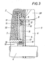
- Fig. 3 den stirnseitigen Anschluß des Zellenrades an die Schleusenkammer, ausschnittsweise im Axialschnitt in einem noch größeren Maßstab.
- 1 is a cross-section of a lock chamber of a discharge device according to the invention which holds a drivable cellular wheel,
- Fig. 2, this lock chamber in an axial section on a larger scale and
- Fig. 3 shows the frontal connection of the cellular wheel to the lock chamber, partially in axial section on an even larger scale.
Um beispielsweise ,Eisenschwamm aus einem Niederschachtofen kontinuierlich austragen zu können, ohne Gefahr zu laufen, daß mit dem heißen Ofengut auch Ofengas austreten kann, ist die Fördereinrichtung zum Austragen des heißen Ofengutes über eine Förderleitung 1 an eine Schleusenkammer 2 angeschlossen, in der ein Zellenrad 3 antreibbar gelagert ist. Dieses Zellenrad 3 besteht aus zwei auf einer Welle 4 sitzenden, stirnseitigen Scheiben 5, zwischen denen die Zellenwände 6 eingesetzt sind. Die Anordnung ist dabei so getroffen, daß die stirnseitigen Scheiben 5 mit axialem Abstand von den Stirnwänden 7 der Schleusenkammer 2 vorgesehen sind, während der radiale Spalt 8 (siehe insbesondere Fig. 3) zwischen dem Zellenrad 3 und der Umfangswand 9 unter Berücksichtigung der möglichen radialen Ausdehnung des Zellenrades 3 gegenüber der Schleusenkammer 2 klein gehalten ist, um einen weitgehend dichten Anschluß des Zellenrades 3 an die Schleusenkammer 2 sicherzustellen. Der sich zwischen den Stirnwänden 7 der Schleusenkammer 2 und den stirnseitigen Scheiben 5 des Zellenrades 3 ergebende Ringraum 10 wird im Bereich des Außenumfanges des Zellenrades 3 durch eine Spaltdichtung abgeschlossen, die aus zwei mit radialem Abstand voneinander angeordneten Ringflanschen 11 an den stirnseitigen Scheiben 5 des Zellenrades 3 und zwei entsprechenden Gegenflanschen 12 an den Stirnwänden 7 der Schleusenkammer 2 gebildet wird. Da jeweils die gegen die Stirnwände 7 axial vorragenden Ringflansche 11 den zugehörigen Gegenflansch 12 außen übergreifen, kann sich bei einer wärmebedingten Ausdehnung des Zellenrades 3 gegenüber der Schleusenkammer 2 keine die Drehung des Zellenrades 3 behindernde Berührung der Flansche 11 und 12 ergeben. Die axiale Dehnung bewirkt lediglich ein axiales Vorschieben der Ringflansche 11 gegen die Stirnwände 7, wobei für diese Relativbewegung ein ausreichendes Dehnungsspiel vorhanden ist. Ein radiales Ausdehnen des Zellenrades 3 bedingt eine Vergrößerung der Dichtspalte 13 zwischen den Ringflanschen 11 und den zugehörigen Gegenflanschen 12, weil sich der radiale Abstand der Ringflansche 11 von der Welle 4 vergrößert. Gleichzeitig wird der radiale Spalt 8 im Ausmaß der Vergrößerung der Dichtspalte 13 verringert, so daß die Dichtwirkung trotz der zu erwartenden unterschiedlichen Ausdehnungen von Zellenrad 3 und Schleusenkammer 2 erhalten bleibt.In order, for example, to be able to discharge sponge iron continuously from a downhole furnace without running the risk that furnace gas can also escape with the hot furnace material, the conveying device for discharging the hot furnace material is connected via a
Damit die Lager 14 für die Welle 4 des Zellenrades 3 vor einer übermäßigen Temperaturbeanspruchung geschützt werden können, sind auf der dem Zellenrad 3 zugewandten Seite der Lager 14 zwischen der Schleusenkammer 2 und der Welle 4 je zwei Ringkanäle 15 und 16 vorgesehen, in die ein Kühlmittel eingeführt werden kann. Zum dichten Abschluß der Ringkanäle 15 gegenüber der Schleusenkammer bildet die Schleusenkammer 2 jeweils einen gegen die stirnseitige Scheibe 5 axial vorragenden Ringflansch 17, der einen Gegenflansch 18 an der stirnseitigen Scheibe 5 des Zellenrades 3 außen mit radialem Abstand übergreift, wobei zwischen dem Ringflansch 17 und dem Gegenflansch 18 ein Gleitring 19 dichtend eingesetzt ist, der beispielsweise aus einer Grafit-Asbestmischung besteht. Dehnt sich der Gegenflansch 18 des Zellenrades 3 gegenüber dem Ringflansch 17 der Schleusenkammer 2 auf Grund unterschiedlicher Temperaturbelastungen stärker aus, so wird der Gleitring 19 zwischen den Flanschen 17 und 18 stärker zusammengedrückt, was die Dichtheit des Ringkanales 15 gegenüber der Schleusenkammer 2 und dem Ringraum 10 erhöht, ohne die Drehbarkeit des Zellenrades 3 störend zu beeinflussen, weil der Gleitring 19 elastisch nachgeben kann.So that the
Das aus einem kalten Inertgas bestehende,-über Leitungen 20 in den Ringraum 15 eingeleitete Kühlmittel führt die aufgenommene Wärme über die Leitungen 21 wieder ab. Der Ringkanal 16, der von dem Ringkanal 15 getrennt ist, wird über die Zuleitungen 22 mit Kühlwasser gefüllt, das über eine mit dem Ringkanal 16 durch Radialbohrungen 23 verbundene Axialbohrung 24 der Welle 4 abgeführt wird. Um die axiale Ausdehnung der Welle 4 zu berücksichtigen, ist die Axialbohrung 24 durch ein verschiebbar in ein Anschlußstück 25 eingreifendes Verlängerungsrohr 26 verlängert. Zum Abführen der Wärme steht somit ein abgestuftes Kühlsystem zur Verfügung, das zulässige Betriebstemperaturen für die Lager 14 der Welle 4 des Zellenrades 3 gewährleistet.The coolant, which consists of a cold inert gas and is introduced into the
Um einen Austritt des unter Druck stehenden Ofengases aus dem Ofen über die Förderleitung 1 zu verhindern, wird die Förderleitung 1 mit Hilfe eines Rohranschlusses 27 an eine Sperrgas-Druckquelle angeschlossen, so daß in der Förderleitung 1 ein Sperrgasdruck größer als der Ofengasdruck aufgebaut werden kann. Der Sperrgasdruck muß jedoch innerhalb der Schleusenkammer 2 abgebaut werden, um einen Austritt des Sperrgases aus der Schleusenkammer 2 weitgehend verhindern zu können. Dies wird mit Hilfe des Zellenrades 3 bewirkt, wobei zwischen dem Schleusenkammereinlaß 28 und dem Schleusenkammerauslaß 29 sowohl im Förderbereich des Zellenrades 3 als auch im gegenüberliegenden Rücklaufbereich eine Abgasleitung 30 vorgesehen ist, die das in die Schleusenkammer 2 eindringende Sperrgas in einen bestehenden Gaskreislauf abführt. Da das Sperrgas erhitzt werden muß, um eine Abkühlung des Ofengutes zu vermeiden, ist eine Kreislaufführung des Sperrgases von erheblicher, wirtschaftlicher Bedeutung.In order to prevent the pressurized furnace gas from escaping from the furnace via the
Damit in der Förderleitung 1 ein entsprechender Sperrgasdurck mit wirtschaftlichen Mitteln aufgebaut werden kann, sollte keine unmittelbare Verbindung zwischen der Förderleitung 1 und den Abgasleitungen 30 bestehen. Der Strömungsweg zwischen dem Schleusenkammereinlaß 28 und den Abgasleitungen 30 muß daher stets durch mindestens eine Zellenwand 6 unterbrochen sein. Um diese Bedingung erfüllen zu können, ist der Winkelabstand Oc zwischen zwei aufeinanderfolgenden Zellenwänden 6 des Zellenrades 3 kleiner als die Winkelabstände Γ der Abgasleitungen 30 vom Schleusenkammereinlaß 28 zu wählen. Die gleiche Bedingung gilt für den Winkelabstand der Abgasleitungen 30 vom Schleusenkammerauslaß 29, um einen Sperrgasdurchtritt zum Schleusenkammerauslaß 29 zu unterbinden. Befinden sich zwei oder mehrere Zellenwände zwischen den Abgasleitungen 30 und dem Schleusenkammerauslaß 29, so wird die Sicherheit gegenüber einem unerwünschten Sperrgasaustritt erhöht.So that a corresponding sealing gas pressure can be built up economically in the
Das Zellenrad 3, das über ein Kettenrad 31 angetrieben werden kann, fördert das heiße Ofengut durch die Schleusenkammer 2, wobei auf Grund des Abschlusses des freien Durchgangsweges zwischen dem Schleusenkammereinlaß 28 und dem Schleusenkammerauslaß 29 durch das Zellenrad 3 ein bestimmter Sperrdruck im Bereich der Förderleitung 1 aufrecht erhalten werden kann. Die das Zellenrad 3 aufnehmende Schleusenkammer 2 wirkt folglich als Druckschleuse, die das heiße Ofengut durchläßt, so daß ein kontinuierlicher Ofenaustrag gewährleistet werden kann, ohne einen Austrag des Ofengases befürchten zu müssen. Um Wärmeverluste des Ofengutes so gering wie möglich zu halten, weist die Schleusenkammer 2 eine entsprechende Wärmeisolierung 32 auf, die jedoch nicht verhindern kann, daß zwischen dem Zellenrad 3 und der Schleusenkammer 2 ein Temperaturunterschied auftritt, der sich insbesondere beim Anfahren der Druckschleuse aus dem kalten Zustand bemerkbar macht, indem das Zellenrad 3 einer stärkeren Wärmedehnung unterworfen wird. Diese stärkere Wärmedehnung wird durch entsprechende Dehnungsausgleiche konstruktiv aufgefangen, ohne die Schleusenwirkung zu gefährden.The
Claims (8)
Applications Claiming Priority (2)
| Application Number | Priority Date | Filing Date | Title |
|---|---|---|---|
| AT1958/82 | 1982-05-18 | ||
| AT0195882A AT374275B (en) | 1982-05-18 | 1982-05-18 | DISCHARGE DEVICE FOR A SHAFT OVEN |
Publications (3)
| Publication Number | Publication Date |
|---|---|
| EP0094928A2 true EP0094928A2 (en) | 1983-11-23 |
| EP0094928A3 EP0094928A3 (en) | 1984-04-18 |
| EP0094928B1 EP0094928B1 (en) | 1986-07-30 |
Family
ID=3524722
Family Applications (1)
| Application Number | Title | Priority Date | Filing Date |
|---|---|---|---|
| EP83890059A Expired EP0094928B1 (en) | 1982-05-18 | 1983-04-20 | Discharging device for a shaft furnace |
Country Status (6)
| Country | Link |
|---|---|
| US (1) | US4507079A (en) |
| EP (1) | EP0094928B1 (en) |
| JP (1) | JPS58213180A (en) |
| AT (1) | AT374275B (en) |
| CA (1) | CA1212541A (en) |
| DE (1) | DE3364880D1 (en) |
Cited By (2)
| Publication number | Priority date | Publication date | Assignee | Title |
|---|---|---|---|---|
| EP0652055A1 (en) * | 1993-10-07 | 1995-05-10 | IN.TEC. ITALIA INTERNATIONAL ENVIRONMENT TECHNOLOGY S.r.l. | A device and process for pre-treating electronic circuit scraps |
| AT14432U1 (en) * | 2014-06-05 | 2015-11-15 | Binder Co Ag | Process for the expansion of sand grain raw material |
Families Citing this family (2)
| Publication number | Priority date | Publication date | Assignee | Title |
|---|---|---|---|---|
| AT382712B (en) * | 1985-05-10 | 1987-04-10 | Voest Alpine Ag | FEEDING DEVICE FOR A SHAFT OVEN FOR BURNING CARBONATE-CONTAINING MINERAL COMBUSTION |
| JP3623016B2 (en) * | 1995-06-09 | 2005-02-23 | 株式会社チサキ | Vertical firing furnace |
Citations (5)
| Publication number | Priority date | Publication date | Assignee | Title |
|---|---|---|---|---|
| DE333699C (en) * | 1919-07-29 | 1921-03-03 | Fried Krupp Akt Ges | Emptying device for pressurized shaft ovens, silos or the like. |
| DE545354C (en) * | 1929-04-24 | 1932-02-29 | William Henry Smith | Method and device for reducing ores, in particular iron ores |
| US1850009A (en) * | 1928-05-23 | 1932-03-15 | Gronwall Eugen Assar Alexis | Reduction of metals out of their ores |
| FR1374753A (en) * | 1963-11-13 | 1964-10-09 | Furnace feeder | |
| DE1272945B (en) * | 1959-10-20 | 1968-07-18 | Metallurg D Imphy Soc | Process for the immediate reduction of crushed iron ore |
Family Cites Families (7)
| Publication number | Priority date | Publication date | Assignee | Title |
|---|---|---|---|---|
| DE337622C (en) * | 1919-11-05 | 1921-06-03 | Arno Andreas | Circulating emptying drum for shaft ovens |
| DE338413C (en) * | 1919-12-13 | 1921-06-17 | Arno Andreas | Circulating emptying drum for shaft ovens |
| DE345027C (en) * | 1920-12-24 | 1921-12-05 | Arno Andreas | Circulating emptying drum for shaft ovens |
| US2072450A (en) * | 1932-05-13 | 1937-03-02 | Philadelphia & Reading Coal & | Furnace |
| GB1170360A (en) * | 1966-09-28 | 1969-11-12 | Anglo Amer Corp South Africa | Improvements in the Segregation Process for the Treatment of Ores |
| US3850616A (en) * | 1973-10-29 | 1974-11-26 | Armco Steel Corp | Inert gas seal for product discharge from a shaft furnace |
| US4073629A (en) * | 1974-07-30 | 1978-02-14 | Kamyr Inc. | Coal gasification process with improved procedure for continuously discharging ash particles and apparatus therefor |
-
1982
- 1982-05-18 AT AT0195882A patent/AT374275B/en not_active IP Right Cessation
-
1983
- 1983-04-20 DE DE8383890059T patent/DE3364880D1/en not_active Expired
- 1983-04-20 EP EP83890059A patent/EP0094928B1/en not_active Expired
- 1983-05-10 US US06/493,204 patent/US4507079A/en not_active Expired - Fee Related
- 1983-05-17 CA CA000428307A patent/CA1212541A/en not_active Expired
- 1983-05-17 JP JP58085195A patent/JPS58213180A/en active Pending
Patent Citations (5)
| Publication number | Priority date | Publication date | Assignee | Title |
|---|---|---|---|---|
| DE333699C (en) * | 1919-07-29 | 1921-03-03 | Fried Krupp Akt Ges | Emptying device for pressurized shaft ovens, silos or the like. |
| US1850009A (en) * | 1928-05-23 | 1932-03-15 | Gronwall Eugen Assar Alexis | Reduction of metals out of their ores |
| DE545354C (en) * | 1929-04-24 | 1932-02-29 | William Henry Smith | Method and device for reducing ores, in particular iron ores |
| DE1272945B (en) * | 1959-10-20 | 1968-07-18 | Metallurg D Imphy Soc | Process for the immediate reduction of crushed iron ore |
| FR1374753A (en) * | 1963-11-13 | 1964-10-09 | Furnace feeder |
Cited By (3)
| Publication number | Priority date | Publication date | Assignee | Title |
|---|---|---|---|---|
| EP0652055A1 (en) * | 1993-10-07 | 1995-05-10 | IN.TEC. ITALIA INTERNATIONAL ENVIRONMENT TECHNOLOGY S.r.l. | A device and process for pre-treating electronic circuit scraps |
| US5522153A (en) * | 1993-10-07 | 1996-06-04 | Celi; Antonio M. | Device and process for pre-treating electronic circuit scraps |
| AT14432U1 (en) * | 2014-06-05 | 2015-11-15 | Binder Co Ag | Process for the expansion of sand grain raw material |
Also Published As
| Publication number | Publication date |
|---|---|
| ATA195882A (en) | 1983-08-15 |
| AT374275B (en) | 1984-04-10 |
| EP0094928A3 (en) | 1984-04-18 |
| DE3364880D1 (en) | 1986-09-04 |
| EP0094928B1 (en) | 1986-07-30 |
| JPS58213180A (en) | 1983-12-12 |
| CA1212541A (en) | 1986-10-14 |
| US4507079A (en) | 1985-03-26 |
Similar Documents
| Publication | Publication Date | Title |
|---|---|---|
| DE3030686C2 (en) | ||
| DE2633809A1 (en) | HIGH TEMPERATURE FITTING | |
| DE2840097A1 (en) | DEVICE FOR RECOVERY OF HEAT FROM HOT EXHAUST GAS | |
| EP0094928B1 (en) | Discharging device for a shaft furnace | |
| DE2414053A1 (en) | PROCEDURE FOR OPERATING A GAS DYNAMIC PRESSURE SHAFT MACHINE AND DEVICE FOR CARRYING OUT THE PROCESS | |
| DE3928181A1 (en) | COOLING DEVICE FOR A HIGH TEMPERATURE, HIGH PRESSURE VESSEL | |
| DE3014574C2 (en) | Discharge device for coke drying chambers | |
| DE3343299A1 (en) | SHUT-OFF VALVE FOR PIPELINES OF LARGE NOMINAL SIZES, IN PARTICULAR HOT WIND PIPES | |
| WO2018206383A1 (en) | Conveying a material to be conveyed | |
| DE2349926A1 (en) | ROTATING TUBE FURNACE WITH ARC PLASMA HEATING | |
| DE2532109A1 (en) | PRESSURE FURNACE FOR TREATMENT OF PRODUCTS UNDER HIGH TEMPERATURE AND HIGH PRESSURE | |
| DE3939170C2 (en) | Locking flap for a shaft furnace | |
| EP3999452A1 (en) | Conveying a material to be conveyed | |
| DE19628383A1 (en) | Furnace for heat treatment of batches of metal workpieces - with a heating chamber which can be isolated from the pressure and suction chambers of the cooling gas fan | |
| DE4334901C2 (en) | Grate cooler | |
| DE102008011749B4 (en) | Gate unit and high-temperature furnace with such | |
| DE2409818A1 (en) | METHOD FOR HEAT TREATMENT OF FERROUS AND NON-FERROUS METALS | |
| DE19501422C2 (en) | Cooled transition piece between a heat exchanger and a reactor | |
| DE2512235C3 (en) | ||
| DE2022909B2 (en) | FURNACE FEEDING DEVICE | |
| DD154177A3 (en) | DOOR AND DOOR FRAME FOR INDUSTRIAL OVEN | |
| DE1218950B (en) | Device for discharging powdery or grainy materials from collecting containers | |
| DE3447267A1 (en) | DEVICE FOR HEATING CHARGED GOODS | |
| LU83402A1 (en) | LOCK DISCHARGE SYSTEM FOR INDUSTRIAL OVENS | |
| DE377650C (en) | Closed cold box for metallurgical ovens |
Legal Events
| Date | Code | Title | Description |
|---|---|---|---|
| PUAI | Public reference made under article 153(3) epc to a published international application that has entered the european phase |
Free format text: ORIGINAL CODE: 0009012 |
|
| AK | Designated contracting states |
Designated state(s): BE DE FR GB IT LU NL SE |
|
| PUAL | Search report despatched |
Free format text: ORIGINAL CODE: 0009013 |
|
| AK | Designated contracting states |
Designated state(s): BE DE FR GB IT LU NL SE |
|
| 17P | Request for examination filed |
Effective date: 19840928 |
|
| GRAA | (expected) grant |
Free format text: ORIGINAL CODE: 0009210 |
|
| AK | Designated contracting states |
Kind code of ref document: B1 Designated state(s): BE DE FR GB IT LU NL SE |
|
| ITF | It: translation for a ep patent filed |
Owner name: STUDIO INGG. FISCHETTI & WEBER |
|
| REF | Corresponds to: |
Ref document number: 3364880 Country of ref document: DE Date of ref document: 19860904 |
|
| ET | Fr: translation filed | ||
| PG25 | Lapsed in a contracting state [announced via postgrant information from national office to epo] |
Ref country code: LU Free format text: LAPSE BECAUSE OF NON-PAYMENT OF DUE FEES Effective date: 19870430 |
|
| PGFP | Annual fee paid to national office [announced via postgrant information from national office to epo] |
Ref country code: NL Payment date: 19870430 Year of fee payment: 5 |
|
| PLBE | No opposition filed within time limit |
Free format text: ORIGINAL CODE: 0009261 |
|
| STAA | Information on the status of an ep patent application or granted ep patent |
Free format text: STATUS: NO OPPOSITION FILED WITHIN TIME LIMIT |
|
| 26N | No opposition filed | ||
| PG25 | Lapsed in a contracting state [announced via postgrant information from national office to epo] |
Ref country code: GB Effective date: 19880420 |
|
| PG25 | Lapsed in a contracting state [announced via postgrant information from national office to epo] |
Ref country code: SE Effective date: 19880421 |
|
| BERE | Be: lapsed |
Owner name: VOEST-ALPINE A.G. Effective date: 19880430 |
|
| PG25 | Lapsed in a contracting state [announced via postgrant information from national office to epo] |
Ref country code: NL Effective date: 19881101 |
|
| NLV4 | Nl: lapsed or anulled due to non-payment of the annual fee | ||
| GBPC | Gb: european patent ceased through non-payment of renewal fee | ||
| PG25 | Lapsed in a contracting state [announced via postgrant information from national office to epo] |
Ref country code: FR Free format text: LAPSE BECAUSE OF NON-PAYMENT OF DUE FEES Effective date: 19881229 |
|
| PG25 | Lapsed in a contracting state [announced via postgrant information from national office to epo] |
Ref country code: DE Effective date: 19890103 |
|
| REG | Reference to a national code |
Ref country code: FR Ref legal event code: ST |
|
| PG25 | Lapsed in a contracting state [announced via postgrant information from national office to epo] |
Ref country code: BE Effective date: 19890430 |
|
| EUG | Se: european patent has lapsed |
Ref document number: 83890059.5 Effective date: 19890726 |