US1850009A - Reduction of metals out of their ores - Google Patents
Reduction of metals out of their ores Download PDFInfo
- Publication number
- US1850009A US1850009A US343476A US34347629A US1850009A US 1850009 A US1850009 A US 1850009A US 343476 A US343476 A US 343476A US 34347629 A US34347629 A US 34347629A US 1850009 A US1850009 A US 1850009A
- Authority
- US
- United States
- Prior art keywords
- furnace
- gases
- shaft
- oxygen
- ores
- Prior art date
- Legal status (The legal status is an assumption and is not a legal conclusion. Google has not performed a legal analysis and makes no representation as to the accuracy of the status listed.)
- Expired - Lifetime
Links
- 229910052751 metal Inorganic materials 0.000 title description 13
- 239000002184 metal Substances 0.000 title description 13
- 150000002739 metals Chemical class 0.000 title description 11
- 230000009467 reduction Effects 0.000 title description 9
- 239000007789 gas Substances 0.000 description 48
- QVGXLLKOCUKJST-UHFFFAOYSA-N atomic oxygen Chemical compound [O] QVGXLLKOCUKJST-UHFFFAOYSA-N 0.000 description 15
- 238000000034 method Methods 0.000 description 15
- 239000001301 oxygen Substances 0.000 description 15
- 229910052760 oxygen Inorganic materials 0.000 description 15
- XEEYBQQBJWHFJM-UHFFFAOYSA-N Iron Chemical compound [Fe] XEEYBQQBJWHFJM-UHFFFAOYSA-N 0.000 description 14
- CURLTUGMZLYLDI-UHFFFAOYSA-N Carbon dioxide Chemical compound O=C=O CURLTUGMZLYLDI-UHFFFAOYSA-N 0.000 description 12
- OKTJSMMVPCPJKN-UHFFFAOYSA-N Carbon Chemical compound [C] OKTJSMMVPCPJKN-UHFFFAOYSA-N 0.000 description 11
- 229910052799 carbon Inorganic materials 0.000 description 11
- 230000008569 process Effects 0.000 description 9
- MYMOFIZGZYHOMD-UHFFFAOYSA-N Dioxygen Chemical compound O=O MYMOFIZGZYHOMD-UHFFFAOYSA-N 0.000 description 8
- 229910001882 dioxygen Inorganic materials 0.000 description 8
- 229910052742 iron Inorganic materials 0.000 description 7
- 229910002092 carbon dioxide Inorganic materials 0.000 description 6
- 239000001569 carbon dioxide Substances 0.000 description 6
- 238000003723 Smelting Methods 0.000 description 5
- 229910000831 Steel Inorganic materials 0.000 description 5
- 239000003638 chemical reducing agent Substances 0.000 description 5
- 239000007788 liquid Substances 0.000 description 5
- 239000010959 steel Substances 0.000 description 5
- 238000007664 blowing Methods 0.000 description 4
- 239000003245 coal Substances 0.000 description 4
- 238000002485 combustion reaction Methods 0.000 description 4
- 238000004519 manufacturing process Methods 0.000 description 4
- 239000000463 material Substances 0.000 description 4
- CWYNVVGOOAEACU-UHFFFAOYSA-N Fe2+ Chemical compound [Fe+2] CWYNVVGOOAEACU-UHFFFAOYSA-N 0.000 description 3
- 229910001296 Malleable iron Inorganic materials 0.000 description 3
- UFHFLCQGNIYNRP-UHFFFAOYSA-N Hydrogen Chemical compound [H][H] UFHFLCQGNIYNRP-UHFFFAOYSA-N 0.000 description 2
- 238000010521 absorption reaction Methods 0.000 description 2
- 229910002091 carbon monoxide Inorganic materials 0.000 description 2
- 238000009826 distribution Methods 0.000 description 2
- 239000001257 hydrogen Substances 0.000 description 2
- 229910052739 hydrogen Inorganic materials 0.000 description 2
- 239000000203 mixture Substances 0.000 description 2
- 238000011946 reduction process Methods 0.000 description 2
- XLYOFNOQVPJJNP-UHFFFAOYSA-N water Substances O XLYOFNOQVPJJNP-UHFFFAOYSA-N 0.000 description 2
- UGFAIRIUMAVXCW-UHFFFAOYSA-N Carbon monoxide Chemical compound [O+]#[C-] UGFAIRIUMAVXCW-UHFFFAOYSA-N 0.000 description 1
- BVKZGUZCCUSVTD-UHFFFAOYSA-L Carbonate Chemical compound [O-]C([O-])=O BVKZGUZCCUSVTD-UHFFFAOYSA-L 0.000 description 1
- 229910000805 Pig iron Inorganic materials 0.000 description 1
- 241000193803 Therea Species 0.000 description 1
- 241001421775 Thereus Species 0.000 description 1
- ATJFFYVFTNAWJD-UHFFFAOYSA-N Tin Chemical compound [Sn] ATJFFYVFTNAWJD-UHFFFAOYSA-N 0.000 description 1
- QCWXUUIWCKQGHC-UHFFFAOYSA-N Zirconium Chemical compound [Zr] QCWXUUIWCKQGHC-UHFFFAOYSA-N 0.000 description 1
- 239000003513 alkali Substances 0.000 description 1
- 230000008901 benefit Effects 0.000 description 1
- 239000003610 charcoal Substances 0.000 description 1
- 229940106265 charcoal Drugs 0.000 description 1
- 238000006243 chemical reaction Methods 0.000 description 1
- 238000000354 decomposition reaction Methods 0.000 description 1
- 230000008014 freezing Effects 0.000 description 1
- 238000007710 freezing Methods 0.000 description 1
- 238000010438 heat treatment Methods 0.000 description 1
- 238000012986 modification Methods 0.000 description 1
- 230000004048 modification Effects 0.000 description 1
- 230000003647 oxidation Effects 0.000 description 1
- 238000007254 oxidation reaction Methods 0.000 description 1
- 238000012856 packing Methods 0.000 description 1
- 238000005192 partition Methods 0.000 description 1
- 230000001105 regulatory effect Effects 0.000 description 1
- 230000008439 repair process Effects 0.000 description 1
- 239000002893 slag Substances 0.000 description 1
- 239000004575 stone Substances 0.000 description 1
- 239000000126 substance Substances 0.000 description 1
- 229910052721 tungsten Inorganic materials 0.000 description 1
- 229910052726 zirconium Inorganic materials 0.000 description 1
Images

Classifications
-
- C—CHEMISTRY; METALLURGY
- C21—METALLURGY OF IRON
- C21B—MANUFACTURE OF IRON OR STEEL
- C21B13/00—Making spongy iron or liquid steel, by direct processes
- C21B13/02—Making spongy iron or liquid steel, by direct processes in shaft furnaces
- C21B13/023—Making spongy iron or liquid steel, by direct processes in shaft furnaces wherein iron or steel is obtained in a molten state
-
- C—CHEMISTRY; METALLURGY
- C21—METALLURGY OF IRON
- C21B—MANUFACTURE OF IRON OR STEEL
- C21B13/00—Making spongy iron or liquid steel, by direct processes
- C21B13/02—Making spongy iron or liquid steel, by direct processes in shaft furnaces
-
- C—CHEMISTRY; METALLURGY
- C22—METALLURGY; FERROUS OR NON-FERROUS ALLOYS; TREATMENT OF ALLOYS OR NON-FERROUS METALS
- C22B—PRODUCTION AND REFINING OF METALS; PRETREATMENT OF RAW MATERIALS
- C22B5/00—General methods of reducing to metals
-
- C—CHEMISTRY; METALLURGY
- C21—METALLURGY OF IRON
- C21B—MANUFACTURE OF IRON OR STEEL
- C21B2100/00—Handling of exhaust gases produced during the manufacture of iron or steel
- C21B2100/20—Increasing the gas reduction potential of recycled exhaust gases
- C21B2100/22—Increasing the gas reduction potential of recycled exhaust gases by reforming
-
- C—CHEMISTRY; METALLURGY
- C21—METALLURGY OF IRON
- C21B—MANUFACTURE OF IRON OR STEEL
- C21B2100/00—Handling of exhaust gases produced during the manufacture of iron or steel
- C21B2100/20—Increasing the gas reduction potential of recycled exhaust gases
- C21B2100/26—Increasing the gas reduction potential of recycled exhaust gases by adding additional fuel in recirculation pipes
-
- Y—GENERAL TAGGING OF NEW TECHNOLOGICAL DEVELOPMENTS; GENERAL TAGGING OF CROSS-SECTIONAL TECHNOLOGIES SPANNING OVER SEVERAL SECTIONS OF THE IPC; TECHNICAL SUBJECTS COVERED BY FORMER USPC CROSS-REFERENCE ART COLLECTIONS [XRACs] AND DIGESTS
- Y02—TECHNOLOGIES OR APPLICATIONS FOR MITIGATION OR ADAPTATION AGAINST CLIMATE CHANGE
- Y02P—CLIMATE CHANGE MITIGATION TECHNOLOGIES IN THE PRODUCTION OR PROCESSING OF GOODS
- Y02P10/00—Technologies related to metal processing
- Y02P10/10—Reduction of greenhouse gas [GHG] emissions
- Y02P10/134—Reduction of greenhouse gas [GHG] emissions by avoiding CO2, e.g. using hydrogen
Definitions
- This invention relates to an im roved process for reducin metals out their ores.
- the metal may be obtained as iron -sponge, pig-iron, steel or malleable iron.
- the process is also suitable for reducing out such other metals than iron that can be reduced out directly or indirectly by means upon the gases thus heated are led into the charge consisting-of partly reduced ore and carbon in the lowerpart of the shaft-furnace.
- the furnace shaft is channels 8 in the lower part of the furnace
- I 9 isan inlet pipe for oxygen connected with a ring pipe 10 that by means of pipes 11 communicates with the combustion room 12, into which the oxygen is blown and then mixed with the circulation gas, so that a'corresponding part of the latter is combusted.
- 13 is the hearth and 14-its bottom. 15 signifies radially arranged partition walls that support the shaft and at the same time,
- the hearth is as usual provided with tym stone and hearth opening (not shown in ig. 1).
- Fig. 2 shows a section through a somewhat modified shaft furnace that is especially suitable for the production of steel or malleable iron, and also other metals.
- 16 is the shaft, 17 the charging floor, 18 the charging throat, 19 an outlet pipe for the circulation gases, 20 an inlet pipe for circulation gases, that communicate with a distribution pipe 21 for said gases, which through the branch pipes 22 are blown into the channel or channels 23 in the furnace, where they cool the lower part suitably provided with an arched bottom.
- the tap hole for metal and slag, 30 is the bottom of the furnace, made out of highly refractory and slag-proof material, for example zirconium ore.
- Fig. 3 illustrates a third form of shaft furnace that is especially suitable for the prov duction of iron-sponge 1n accordance with the invention.
- it is suitable to let the circulation gases pass through a carburettor before reentering the furnace.
- a quantity of oxygen is blown into the circulation gases so that a part of them is combusted, whereupon the hot gases are led through a coal tower and from there back into the furnace as described above in connection with Figs. 1 and 2.
- the lower part of the shaft is formed as a room, where the iron-spongeis cooled by means of water-cooled wall-plates 31. 32 is a device for feeding out the iron-sponge.
- the reduction furnace is connected by means of gas piping with a recuperator 33, in which the gases from the furnace give off a great part of their heat and are led away by the pipe 35.
- the gases have been purified and liberated from CO the same are brought to the recuperator through the pipe 34, and are preheated and thereu on led intothe carburettor arranged therea ove, in whose combustion chamber 36 a partof the gases is combusted by oxygen blown in through the pipe 37.
- the gases thus heated are carburetted b leading them through the coal tower 38.
- the carburetted gas is mixed with a quantity of gas that is led into the chamber 39 directly from the recuperator 33. From the chamber 39 the gases are I led back into the furnace, wherein a part of them is combusted by oxygen as described above.
- the charge will have a certain tendency of packing together or hanging, and brlttle briquettes, especially briquettes with char-coal, will easily break too early by the pressure in the shaft.
- This can be avoided by giving the shaft a square or rectangular cross-section, and by arranging at suitable places in the shaft rotating or rotatable members in such away that they partly neutralize the pressure of the pile of charging material and by their rotation prevent the material from hanging or being jammed during its passage down through the shaft. In this way the resistance against the flow of the heat delivering and partly reducing gases through the charge can be kept within reasonable limits.
- That sort of shaft is especially well adapted for the reduction of iron sponge, but also for other purposes. I! or charges of a more powdery consistence one may use a low shaft furnace combined in the known way with one or several horizontal and rotating preheating or reduction drums.
- the oxygen required for the process may be generated in several differentways.
- oxygen gen-- eration the former is as a rule to be preferred on account of the low power consumption 're quired.
- the oxygen gas may be stored either in gas form or in a liquid state in suitable containers. In this way a reserve supply can be provided so that a shorter stop in the oxy- In cases gen manufacture will have no influence upon the continual working of the furnace.
- Process for reducing metals in; shaft furnaces out of their ores by means of carbonaceous reducing agents at 1700 C. comprising removing carbon dioxide out of gases escaping from the furnace, blowing the remaininggases back into the charge in the lower part of the shaft furnace, after having blown into the furnace in apart of the furnace communlcating with the smelting room such a quantity of oxygen gas that only a part of their. content of combustible. gases is combusted, and keeping the gases continually in circulationthrough the charge and furnace,
- said oxygen gas being obtained by rectifying liquid air.
- Process for producin metals-in shaft furnaces out of their ores y means ofcarbonaceous reducing agentsat 1700 0. comprising removing carbon dixoide out of gases escaping from the furnace, combusting a part of said treated gases with 0 tin the gas mixture by lea g-it through co, blowing the gases back into the-charge in the lower part of the shaft furnace, after havin blown into the furnace such a-quantity 0 oxygen as that only a part of their content of comliustible gases is combusted, and keeping the gases continually in circulation through the charge and furnace, said oxygen gas being obtained by rectifying. liquid air.
- Process for reducing metals in shaft furnaces out of their ores by means of carbonaceous reducing agents comprising removing carbon dioxide out of the gases formed during the reduction process and escaping from the furnace, forcing the remaining back into the charge in 'the lower part of the furnace after mixing said ases with such a uantity of oxygen gas at such apart of t e combustible content of said gases is comand furnace.
- Process for reducing metals in shaft fur l naces out of their' ores by means of carbonaceous reducing agents comprising removing carbon dioxide out ofthe gases formed durthe reduction process and escaping from a the furnace, forcinglthe remaining gases back naceous reducing agents, comprising'removing carbon dioxide out of gases escaping from the furnace, combustin a part of said treated gases with oxygen, car uretting the as mixture by leading; it through hot coal, lowing the gases back into the charge in the lower part of the shaft furnace, after having blown into said gases such a quantity of oxygen gas that only a part of their content of combustible gases is combusted, and keeping the gases continually in circulation through the charge 7 and furnace.
Landscapes
- Engineering & Computer Science (AREA)
- Chemical & Material Sciences (AREA)
- Manufacturing & Machinery (AREA)
- Materials Engineering (AREA)
- Metallurgy (AREA)
- Organic Chemistry (AREA)
- Mechanical Engineering (AREA)
- Manufacture And Refinement Of Metals (AREA)
Description
Mamh 15, 1932. I E. A. A. GRONWALL. ET AL. 1,850,009
REDUCTION OF METALS OUT OF THEIR ORES .2 Sheets-Sheet 1 Filed Feb. 28, 1929 nww Q 1 Mum/001K %W March 15, 1932. E. A. A. GRONWALL E'i' AL 1,850,009 Y REDUCTION OF METALS OUT OF THEIR ORES Filed Feb. 28, 1929 2 Sheets-Shee t 2 Patented Mar. 15, 1932 UNITED STATES PATENT? OFFICE EUGEN Assan ALEXIS enonwann am) nanmr'aomm xterm ira'monsr, or
srocxnonm, swarm:
REDUCTION OF METALS OUT OF THEIR ORES Application filed February 28, 1329, Serial No. 843,478, and in Sweden Kay 28, 1928.
This invention relates to an im roved process for reducin metals out their ores. When reducing 1ron ores in accordance with this invention, the metalmay be obtained as iron -sponge, pig-iron, steel or malleable iron. The process is also suitable for reducing out such other metals than iron that can be reduced out directly or indirectly by means upon the gases thus heated are led into the charge consisting-of partly reduced ore and carbon in the lowerpart of the shaft-furnace.
By allowing a surplus of CO to circulate 25 in te furnace, the combustion temperature and the heating temperature can be kept at the desired height. y blowing for instance 13,5 05 into 115 G0, a gas is obtained consisting of 88CO+27GO at 1700 C. The theoretical course of reaction would in this case be the following 9Fe O +88CO+27C+27COz= 18Fe+115CO+27CO2.
whereupon they are cooled and washed in a suitable way, and thereupon passed to a device for removin the content of CO This may be eifected y liquidifying or freezing after the Linde-method, by absorption in water under pressure, or by chemical absorp-v tion in alkali carbonate that is regenerated in a known way. The purified gas, now consisting of 115 CO, is sent back, cold or pre- V heated, to the furnace and is there again part- 1y combusted with 13,5 0 whereupon the above related course is repeated; that is, the
gas is made to circulate. In the practise it is 50 absorption of 85% CO is considered satis- From the furnace 115CO+27CO are led off,
not necessary to wash out all CO If an factory, an equilibrium will be reached when the gas consists of 115CO+4,75CO' By varying'the quantity of circulating gas as well as the quantity of oxygen and carbon, the reducing and smelting temperatures can be varied; when smelting is not needed the reduction temperature alone can be varied.
But' it is also apparent that bya suitable proportioning between oxygen and carbon all theadmixed carbon will be combusted 01'' oxidized to carbon dioxide and that thus no excess of carbon monoxide will arise.
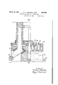
By way of example we have shown in the accompanying dratvings in Fi s. 1, 2 and 3 in longitudinal section three sha t furnaces that can be used for carryingfout a reducing process in accordance with this invention.
According to Fig. 1, the furnace shaft is channels 8 in the lower part of the furnace,
where the gas in a certain degree cools the lower part ofthe furnace walls and the underlying arch. I 9 isan inlet pipe for oxygen connected with a ring pipe 10 that by means of pipes 11 communicates with the combustion room 12, into which the oxygen is blown and then mixed with the circulation gas, so that a'corresponding part of the latter is combusted. 13 is the hearth and 14-its bottom. 15 signifies radially arranged partition walls that support the shaft and at the same time,
divide channels and combustion rooms in suitable sections. The hearth is as usual provided with tym stone and hearth opening (not shown in ig. 1).
Fig. 2 shows a section through a somewhat modified shaft furnace that is especially suitable for the production of steel or malleable iron, and also other metals. 16 is the shaft, 17 the charging floor, 18 the charging throat, 19 an outlet pipe for the circulation gases, 20 an inlet pipe for circulation gases, that communicate with a distribution pipe 21 for said gases, which through the branch pipes 22 are blown into the channel or channels 23 in the furnace, where they cool the lower part suitably provided with an arched bottom.
28 is a door for smaller repairs, and 29 the tap hole for metal and slag, 30 is the bottom of the furnace, made out of highly refractory and slag-proof material, for example zirconium ore.
Fig. 3 illustrates a third form of shaft furnace that is especiallysuitable for the prov duction of iron-sponge 1n accordance with the invention. In such a case it is suitable to let the circulation gases pass through a carburettor before reentering the furnace. In said carburettor a quantity of oxygen is blown into the circulation gases so that a part of them is combusted, whereupon the hot gases are led through a coal tower and from there back into the furnace as described above in connection with Figs. 1 and 2.
' The lower part of the shaft is formed as a room, where the iron-spongeis cooled by means of water-cooled wall-plates 31. 32 is a device for feeding out the iron-sponge. The reduction furnace is connected by means of gas piping with a recuperator 33, in which the gases from the furnace give off a great part of their heat and are led away by the pipe 35. When the gases have been purified and liberated from CO the same are brought to the recuperator through the pipe 34, and are preheated and thereu on led intothe carburettor arranged therea ove, in whose combustion chamber 36 a partof the gases is combusted by oxygen blown in through the pipe 37. The gases thus heated are carburetted b leading them through the coal tower 38. n the chamber 39 the carburetted gas is mixed with a quantity of gas that is led into the chamber 39 directly from the recuperator 33. From the chamber 39 the gases are I led back into the furnace, wherein a part of them is combusted by oxygen as described above.
In certain cases -the charge will have a certain tendency of packing together or hanging, and brlttle briquettes, especially briquettes with char-coal, will easily break too early by the pressure in the shaft. This can be avoided by giving the shaft a square or rectangular cross-section, and by arranging at suitable places in the shaft rotating or rotatable members in such away that they partly neutralize the pressure of the pile of charging material and by their rotation prevent the material from hanging or being jammed during its passage down through the shaft. In this way the resistance against the flow of the heat delivering and partly reducing gases through the charge can be kept within reasonable limits. That sort of shaft is especially well adapted for the reduction of iron sponge, but also for other purposes. I! or charges of a more powdery consistence one may use a low shaft furnace combined in the known way with one or several horizontal and rotating preheating or reduction drums.
By correctly determining the proportions between carbon and ore, it is possible by the present invention to produce iron or steel with the approximate carbon content that is desired, but it is also possible to produce an iron sponge practically free from carbon.
The oxygen required for the process may be generated in several differentways. One
way is using the Lin'de-process or modifications thereof, wherein the oxygen is obtained by rectifying liquidaair. Another way is the electrolytic decomposition of water, also hydrogen then being obtained wherefore this method is best suitable when the hydrogen can be disposed of at such conditions that the oxygen is obtained at low cost. when there is access to cheap electric power, and coal at the same time is expensive, the hydrogenor at least a part thereofmay be blown into the surface and in such way reduce the carbon consumption.
Of the two named examples of oxygen gen-- eration the former is as a rule to be preferred on account of the low power consumption 're quired.
The oxygen gas may be stored either in gas form or in a liquid state in suitable containers. In this way a reserve supply can be provided so that a shorter stop in the oxy- In cases gen manufacture will have no influence upon the continual working of the furnace.
Compared with the common blast furnace,
a shaft furnace working after thepresent method will offer a considerable saving of carbon that, however, in some degree is counteracted by a higher power consumption. Even in the case that the oxygen is generated out of liquid air produced by means of a machinery driven by steam or internal com- "bustion engines, the total carbon consumption pr. ton iron or steel will be essentially lower. Since the oxygen is completely consumed' before the hot gases enter the pile of charging material and a great surplus of CO 'exists, no oxidation of already reduced out metal can occur as in a common blast furnace. Concerning direct production of steel or malleable iron the present method as compared with previously knownelectrothermic methods has the advantage of essentially lower power consumption and lower maximum temperature-thereby causing less strain to the furnace-a more even distribution of temperature in the smelting room, and
a greater possibility of regulating the smelt-- ing temperature. The possibility of exact regulation of the reduction temperature is of v a great value at the production of iron sponge.
We claim 1. Process for reducing metals in shaft furnaces out of their oresby means of carbonaceous reducing agents at 1700 C., comprising removing carbon dioxide out of gases escaping from the furnace, blowing the remaining gases back into the charge in the lower part of the shaft furnace, after having blown into the furnace such a quantity of oxygen gas that only a part of their content of combustible gases is combusted, and keeping the gases continually in circulation through the charge and furnace said oxygen gas being obtained by rectifying liquid air.
2. Process for reducing metals in; shaft furnaces out of their ores by means of carbonaceous reducing agents at 1700 C. comprising removing carbon dioxide out of gases escaping from the furnace, blowing the remaininggases back into the charge in the lower part of the shaft furnace, after having blown into the furnace in apart of the furnace communlcating with the smelting room such a quantity of oxygen gas that only a part of their. content of combustible. gases is combusted, and keeping the gases continually in circulationthrough the charge and furnace,
said oxygen gas being obtained by rectifying liquid air.
3. Process for producin metals-in shaft furnaces out of their ores y means ofcarbonaceous reducing agentsat 1700 0., comprising removing carbon dixoide out of gases escaping from the furnace, combusting a part of said treated gases with 0 tin the gas mixture by lea g-it through co, blowing the gases back into the-charge in the lower part of the shaft furnace, after havin blown into the furnace such a-quantity 0 oxygen as that only a part of their content of comliustible gases is combusted, and keeping the gases continually in circulation through the charge and furnace, said oxygen gas being obtained by rectifying. liquid air.
4. Process for reducing metals in shaft furnaces out of their ores by means of carbonaceous reducing agents, comprising removing carbon dioxide out of the gases formed during the reduction process and escaping from the furnace, forcing the remaining back into the charge in 'the lower part of the furnace after mixing said ases with such a uantity of oxygen gas at such apart of t e combustible content of said gases is comand furnace.
- 5. Process for reducing metals in shaft fur l naces out of their' ores by means of carbonaceous reducing agents, comprising removing carbon dioxide out ofthe gases formed durthe reduction process and escaping from a the furnace, forcinglthe remaining gases back naceous reducing agents, comprising'removing carbon dioxide out of gases escaping from the furnace, combustin a part of said treated gases with oxygen, car uretting the as mixture by leading; it through hot coal, lowing the gases back into the charge in the lower part of the shaft furnace, after having blown into said gases such a quantity of oxygen gas that only a part of their content of combustible gases is combusted, and keeping the gases continually in circulation through the charge 7 and furnace.
i In testimony setour hands.
. HUGE" ASSAR ALEXIS GRONWALL.
- HARRY-1011A IUALHAR IIA'IHORST.
whereof we have hereunto gen, carburet-
Applications Claiming Priority (1)
| Application Number | Priority Date | Filing Date | Title |
|---|---|---|---|
| SE1850009X | 1928-05-23 |
Publications (1)
| Publication Number | Publication Date |
|---|---|
| US1850009A true US1850009A (en) | 1932-03-15 |
Family
ID=20423782
Family Applications (1)
| Application Number | Title | Priority Date | Filing Date |
|---|---|---|---|
| US343476A Expired - Lifetime US1850009A (en) | 1928-05-23 | 1929-02-28 | Reduction of metals out of their ores |
Country Status (1)
| Country | Link |
|---|---|
| US (1) | US1850009A (en) |
Cited By (5)
| Publication number | Priority date | Publication date | Assignee | Title |
|---|---|---|---|---|
| US2598735A (en) * | 1948-07-16 | 1952-06-03 | Hydrocarbon Research Inc | Iron oxide reduction |
| US2786665A (en) * | 1954-06-09 | 1957-03-26 | Oscar F Swenson | Apparatus for smelting ores |
| US3231254A (en) * | 1959-11-24 | 1966-01-25 | Raick Julien Oscar | Apparatus for handling and mixing blast furnace gaseous materials |
| EP0094928A3 (en) * | 1982-05-18 | 1984-04-18 | Voest-Alpine Aktiengesellschaft | Discharging device for a shaft furnace |
| EP0241732A3 (en) * | 1986-03-17 | 1988-12-21 | Hylsa, S.A. | Method and apparatus for producing hot direct reduced iron |
-
1929
- 1929-02-28 US US343476A patent/US1850009A/en not_active Expired - Lifetime
Cited By (5)
| Publication number | Priority date | Publication date | Assignee | Title |
|---|---|---|---|---|
| US2598735A (en) * | 1948-07-16 | 1952-06-03 | Hydrocarbon Research Inc | Iron oxide reduction |
| US2786665A (en) * | 1954-06-09 | 1957-03-26 | Oscar F Swenson | Apparatus for smelting ores |
| US3231254A (en) * | 1959-11-24 | 1966-01-25 | Raick Julien Oscar | Apparatus for handling and mixing blast furnace gaseous materials |
| EP0094928A3 (en) * | 1982-05-18 | 1984-04-18 | Voest-Alpine Aktiengesellschaft | Discharging device for a shaft furnace |
| EP0241732A3 (en) * | 1986-03-17 | 1988-12-21 | Hylsa, S.A. | Method and apparatus for producing hot direct reduced iron |
Similar Documents
| Publication | Publication Date | Title |
|---|---|---|
| US3460934A (en) | Blast furnace method | |
| US2750277A (en) | Process and apparatus for reducing and smelting iron | |
| US2526658A (en) | Process for smelting iron ore | |
| US1871848A (en) | Process for producing metal sponge | |
| PL76243B1 (en) | ||
| US3236628A (en) | Process and plant for producing molten pig iron | |
| US1850009A (en) | Reduction of metals out of their ores | |
| SU1138036A3 (en) | Method of operation of blast furnace and system for producing molten iron and reducing gas | |
| US2035550A (en) | Process for producing pig iron or steel simultaneously with portland cement | |
| US4455165A (en) | Increasing blast temperature | |
| US2515670A (en) | Manufacture of open-hearth steel | |
| US2057554A (en) | Method of and apparatus for the reduction of oxide ores | |
| US2795497A (en) | Method and apparatus for producing molten iron | |
| US2799576A (en) | Process for operating shaft blast furnaces | |
| US2219046A (en) | Treatment of iron ores | |
| US2727816A (en) | Method for reduction-smelting of ferrous materials in a modified blast furnace with a specific combination of gaseous injection at two levels | |
| US2203778A (en) | Method for producing steel | |
| US2175517A (en) | Method of utilizing fuel oils in the operation of iron blast furnaces | |
| US1803686A (en) | Gas production | |
| US1360711A (en) | Process for the manufacture of iron and steel directly from the ore and improved apparatus therefor | |
| US470481A (en) | Blast furnace and means foe operatinfj the same | |
| US1558965A (en) | Apparatus for treating ores or the like | |
| US1284094A (en) | Manufacture of steel direct from iron ores. | |
| US2635957A (en) | Process for reducing ores | |
| US267525A (en) | Ments |