EP0094901A2 - Minenräumgerät zum Aufbau auf Fahrzeugen - Google Patents
Minenräumgerät zum Aufbau auf Fahrzeugen Download PDFInfo
- Publication number
- EP0094901A2 EP0094901A2 EP83630082A EP83630082A EP0094901A2 EP 0094901 A2 EP0094901 A2 EP 0094901A2 EP 83630082 A EP83630082 A EP 83630082A EP 83630082 A EP83630082 A EP 83630082A EP 0094901 A2 EP0094901 A2 EP 0094901A2
- Authority
- EP
- European Patent Office
- Prior art keywords
- vehicle
- orientation
- frame
- raised
- mines
- Prior art date
- Legal status (The legal status is an assumption and is not a legal conclusion. Google has not performed a legal analysis and makes no representation as to the accuracy of the status listed.)
- Ceased
Links
- 230000004888 barrier function Effects 0.000 claims description 3
- 238000006073 displacement reaction Methods 0.000 claims description 2
- 238000000034 method Methods 0.000 abstract description 2
- 230000006835 compression Effects 0.000 description 3
- 238000007906 compression Methods 0.000 description 3
- 238000010276 construction Methods 0.000 description 3
- 230000000712 assembly Effects 0.000 description 2
- 238000000429 assembly Methods 0.000 description 2
- 238000006243 chemical reaction Methods 0.000 description 1
- 230000006837 decompression Effects 0.000 description 1
- 230000009977 dual effect Effects 0.000 description 1
- 230000005484 gravity Effects 0.000 description 1
- 238000009434 installation Methods 0.000 description 1
- 230000003014 reinforcing effect Effects 0.000 description 1
- 238000005096 rolling process Methods 0.000 description 1
- 239000002689 soil Substances 0.000 description 1
Images


Classifications
-
- F—MECHANICAL ENGINEERING; LIGHTING; HEATING; WEAPONS; BLASTING
- F41—WEAPONS
- F41H—ARMOUR; ARMOURED TURRETS; ARMOURED OR ARMED VEHICLES; MEANS OF ATTACK OR DEFENCE, e.g. CAMOUFLAGE, IN GENERAL
- F41H11/00—Defence installations; Defence devices
- F41H11/12—Means for clearing land minefields; Systems specially adapted for detection of landmines
- F41H11/16—Self-propelled mine-clearing vehicles; Mine-clearing devices attachable to vehicles
- F41H11/20—Self-propelled mine-clearing vehicles; Mine-clearing devices attachable to vehicles with ground-penetrating elements, e.g. with means for removing buried landmines from the soil
- F41H11/24—Self-propelled mine-clearing vehicles; Mine-clearing devices attachable to vehicles with ground-penetrating elements, e.g. with means for removing buried landmines from the soil the elements being ploughs
-
- F—MECHANICAL ENGINEERING; LIGHTING; HEATING; WEAPONS; BLASTING
- F41—WEAPONS
- F41H—ARMOUR; ARMOURED TURRETS; ARMOURED OR ARMED VEHICLES; MEANS OF ATTACK OR DEFENCE, e.g. CAMOUFLAGE, IN GENERAL
- F41H11/00—Defence installations; Defence devices
- F41H11/12—Means for clearing land minefields; Systems specially adapted for detection of landmines
- F41H11/16—Self-propelled mine-clearing vehicles; Mine-clearing devices attachable to vehicles
- F41H11/28—Self-propelled mine-clearing vehicles; Mine-clearing devices attachable to vehicles using brushing or sweeping means or dozers to push mines lying on a surface aside; using means for removing mines intact from a surface
Definitions
- the present invention relates to apparatus for clearing mines, and more particularly to mine clearing apparatus mountable on an armoured vehicle such as a tank .
- the present invention seeks to provide various improvements to the apparatus for clearing mines described in the aforementioned co-pending Israel Patent Applications.
- mine clearing apparatus for attachement to a vehicle and comprising a frame mountable onto a vehicle for selectable positioning in a raised or lowered orientation; apparatus mounted onto the frame for raising and shunting aside mines including first and second plow sections disposed one above another in hinged engagement, the second plow section being associated with a plurality of plow teeth which, in operation, extend below the ground surface, the first and second plow sections being oeprative to lie in generally the same plane during operation and in folded engagement when the frame is in its raised orientation , the raising and shunting aside apparatus being mounted on the frame in front of the ground engaging members on each side of the vehicle and being angularly oriented to have a forward edge adjacent the interior of the vehicle and a rearward edge adjacent the side edge of the vehicle, each of the forward edges being provided with a chain attached to the first and second plow sections such as to be tensioned when the first and second plow sections are in their operating orientations to thereby
- apparatus for clearing mines comprising a frame mountable onto a vehicle for selectable positioning in a raised or lowered orientation, apparatus mounted onto the frame for raising and shunting aside mines and apparatus for selectably retaining the frame in a raised orientation and including control apparatus operable from inside the vehicle for selectably releasing the frame from its raised orientation and allowing it to assume its lowered orientation, the selectably retaining apparatus including a hook member pivotably mounted onto the vehicle at a central location on the hook member and having a roller engaging slot at a first end thereof, an intermediate link pivotably coupled to the hook member at a second end thereof opposite to the first end with respect to the central location, an operating lever of elongate configuration, pivotably mounted at a first end thereof onto the vehicle and pivotably attached to the intermediate link at a first intermediate location along the operating lever, a pull cable attached to the operating lever at a second end thereof and a spring connection between a second intermediate location and a fixed location with respect to the vehicle, the selectably
- apparatus for clearing mines comprising a frame mountable onto a vehicle for selectable positioning in a raised or lowered orientation; apparatus mounted onto the frame for raising and shunting aside mines; and a gliding surface supporting the frame h its lowered orientation, the gliding surface being disposed rearwardly of the apparatus for raising and shunting aside mines.
- hydraulic positioning means are provided for governing the orientation of the gliding surface relative to the frame.
- the hydraulic positioning means may be operative in response to the outputs of an orientation sensor mounted onto the vehicle.
- Figs. 1 -5 B illustrate mine clearing apparatus constructed and operative in accordance with an embodiment of the present invention.
- the present description is presented with particular reference to mine clearing apparatus which is mountable onto a particular type of tank, the M-60 Patton. It is appreciated that this is entirely for the purpose of illustration and that the invention is applicable to other types of tanks and possibly other vehicles as well.
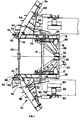
- the mine clearing apparatus comprises a frame 10 including a pair of identical side portions 12 which are joined at their front end by a cross barl4 and at their rear end support an axle 16.
- Frame 10 is rigidly mounted onto an armoured vehicle such as a M-60 tank in the illustrated embodiment by engagement of pins 17 located at side portions 12 with tow- line lugs fixed onto the tank .
- Rigidity of mounting is provided by bolts 18 which engage the underside of the tank and force mounting plates 20, fixedly mounted onto side portions 12 on the opposite side of pins 17, into tight engagement with the underside hull of the tank.
- First and second arms 22 and 24 are independently rotatably mounted onto axle 16 and extend forwardly thereof in generally parallel planes. Arms 22 and 24 are strengthened by reinforcing elements 26 and 28 respectively which are fixed at one end thereof to the respective arms and are rotatably mounted by means of clamps 30 and 32 onto axle 16.
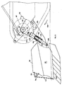
- Mine plowing assembly 34 comprises main plow portion 36, of generally elongate configuration and concave cross section.
- main plow portion 36 may be similar to that of an ordinary vehicle powered snow plow. Disposed above main plow portion 36 and hinged thereonto is an auxiliary plow portion 38. Auxiliary plow portion 38 has two positions, a lowered position in which it extends forwardly of the surface of main plow portion 36 and a raised position in which it defines an upper continuation of the surface of the main plow portion 36.
- This hinged construction is to obviate the problem of interference with a drivers field of vision or with the range of operation of the armament on a tank.
- the hinged auxiliary plow portion 38 may be lowered when the plowing assembly 34 is in its raised orientation.
- main plow portion 36 Disposed below main plow portion 36 there are provided a plurality of vertically disposed planar blades 40, which during operation are disposed below the ground surface.
- the horizontal spacing between adjacent vertical blades is selected to be such that anti-vehicle mines will of necessity be engaged thereby.
- the blades are provided with an inclined forward surface, so as to raise mines located under the ground surface into engagement with main plow portion 36, so that they may be plowed aside.
- a desired depth of operation for blades 40 is determined by means of a gliding surface assembly 42 which is articulatedly mounted onto each of arms 22 and 24 and onto corresponding plow portions 36.
- the gliding surface assembly 42 comprises a sled 44 which is pivotably mounted onto plow portion 36 and is arranged to slide on the ground surface rearwardly of the plow and of blades 40.
- a piston and cylinder combination 46 which is mounted onto each respective arm and sled 44 determines the orientation of the sled relative to the respective arm so as to maintain the blades 40 at a predetermined operating depth. The operation of piston and cylinder combination 46 is controlled in such a way that the blades 40 do not tend to dig deeper and deeper into the ground surface.
- ground surface sensor 48 (Fig. 4) associated with microswitches 49 which respond to the presence and or absence of contact between the sensor 48 and the ground surface and provide a control function through suitable conventional logic control circuitry to the piston and cylinder combination 46, which preferably is hydraulically operated.
- suitable conventional logic control circuitry to the piston and cylinder combination 46, which preferably is hydraulically operated.
- Other types of sensors may also be employed.
- the arrangement of the gliding surface assembly is such that the reaction forces generated by ground engagement of the blades 40 and the remainder of the plowing apparatus are transferred to sled 44 and thus to the ground surface rather than to the vehicle.
- a chain 50 extends from each auxiliary plow portion 38 to a location on the tank hull or onto frame 10.
- the length of the chain 50 is selected such that it is slack when the plowing assembly is in its raised orientation but becomes tight when the plowing assembly is lowered, thus pulling on auxiliary plow portion 38 and orienting it towards a generally vertical orientation.
- the full raised orientation of the auxiliary plow portion 38 is reached only when soil being plowed is forced thereagainst.
- An additional chain 52 is disposed at the inner facing edge 53 of each plowing assembly and extends from the lower inner corner of each plow portion 36 to a location 54 defined by the extreme forward facing portion of a bracket 56 disposed on auxiliary plow portion 38.
- the chain is slack and does not interfere with folding of the plow portions or with operation of the vehicle.
- chain 52 is taut and defines a barrier which prevents mines excavated by the plowing assembly from rolling or being directed inwardly of the inner facing edge of the plowing assembly into the region which is unprotected by a plowing assembly.
- a hook member 60 is pivotably mounted about an axis 62 onto each side portion 12 and comprises a socket portion 64 located at one end thereof and a lever portion 66 atanother end thereof and having pivotably mounted thereon at a pivot location 67, an intermediate member 68.
- a selectable release lever 70 is pivotably mounted onto each side portion 12 about an axis 72 and is pivotably mounted onto intermediate member 68 at a pivot location 74.
- a spring 78 joins release lever 70 to a fixed location on each side portion 12. The spring tends to urge the lever 70 to remain in whichever position it is in.
- a cable connection 80 is provided to the interior of the vehicle, such that pulling on the cable is operative to povide counter-clockwise movement of lever 70 about its pivot axis 72 (as seen in Figs. 5A and 5B). It is noted that spring 78 is in an over-center type of arrangement which provides its indicated dual function. It is appreciated that the cable connection may be replaced by any other suitable displacement means, such as a solenoid operated device, actuated from inside the vehicle, for displacing lever 70 as desired.
- Fig. 5A shows a retainer roller 82 which is fixedly mounted onto each of arms 22 and 24 about to engage socket portion 64 and moving in an arc illustrated by an arrow 84. Engagement of roller 82 with a surface 86 of the socket portion forces the hook member to pivot in a clockwise direction about its pivot axis 62(in the sense of Figs. 5A and 5B ).
- the clockwise movement of the hook member 60 causes lever portion 66 to rotate, also in a clockwise sense, and to raise intermediate member 68 causing reorientation of the intermediate member 68 and thus of lever 70 such that pivot location 74 crosses the imaginary line joining pivot locations 67 and 72.
- This over-center orientation is illustrated in Fig. 5B and provides a stable locking orientation of the retaining apparatus. Hook member 60 is thus prevented from counterclockwise rotation into an open orientation. Roller 82 is thus securely engaged by hook member 60 and arms 22 and 24 are maintained in their respective raised orientation, provided that lever 70 remains in the locked position (Fig. 5B).
- Hook member 60 is then free to rotate in a counterclockwise direction about its pivot such that roller pin 82 is released, thus allowing arm 22 or 24 as the case may be and the associated mine plowing assembly 34 to fall by gravity into their respective lowered orientations in engagement with the ground.
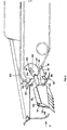
- the apparatus for automatically lifting the mine plowing apparatus comprises a freely rotatable disk segment 90 which is bearing mounted onto a mounting member 92 which is.bolted onto a tension wheel 94 of a tank. Tension wheel 94 engages the tread of a tank and maintains it at a desired tension.
- Mounted on an edge surface of disk segment 90 are first and second spaced teeth 96 and 98 which selectably engage the interstices defined between plates of the tank tread in accordance with an embodiment of the invention.
- Spring supporting apparatus 99 comprises a spring housing 100 which is rotatably mounted at a first end thereof onto mounting pin 95 and a spring compressing rod 105 which is connected at an exterior end thereof to a location 102 fixed onto the main plow portion 36.
- Spring supporting apparatus 99 may be generally described as comprising a spring loaded extensible support member formed of elements 100 and 105 and comprising first and second springs 101 and 103 arranged in a series arrangement.
- Springs 101 and 103 preferably have greatly different spring forces.
- spring 101 is an ordinary heavy duty coil spring while spring 103 comprises a series of independent disk or belleville springs which are characterized in that they undergo complete compression at a compressive force of about 7 ton. It is appreciated that any other suitable spring arrangement may be employed alternatively and that the arrangement of apparatus 99 is such that extension of apparatus 99 produces compression of springs 101 and 103.
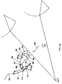
- disk segment 90 In order to understand the operation of the automatic lifting apparatus, it is necessary to appreciate the details of construction of disk segment 90 and the relative positions of teeth 96 and 98 and pin 95 thereon.
- the direction of motion of the tank treads during reverse motion of the tank is indicated by an arrow 104.
- the disk segment 90 Upon engagement of at least one of teeth 96 and 98 with the tank treads, the disk segment 90 is caused to rotate in a clockwise direction, indicated by an arrow 106 about pivot location 93.
- pin 95 leads tooth 96 by about 20° and tooth 96 leads tooth 98 by about 90°.
- Fig. 3 shows the plowing assembly in a fully lowered plowing orientation prior to engagement of tooth 96 with the tank treads.
- spring 101 is compressed to about one-half of its maximum length. This is the orientation during forward mine clearing operation of the tank .
- the tank When it is desired to raise the mine clearing apparatus to a raised orientation, the tank simply shifts to reverse motion. Due to the position of tooth 96 which is pressed against the tank tread during motion in a forward direction as illustrated in Fig. 3, reverse motion of the tank tread in a direction indicated by arrow 104, tends to draw tooth 36 into driven engagement therewith, causing clockwise rotation of disk segment 90 in a direction indicated by arrow 107. An initial backwards movement of the tank causes the blades 40 to lie on the ground surface instead of being buried partially therebelow.
- the disk segment 90 With continued backwards movement of the tank treads, the disk segment 90 continues to rotate due to the engagement of tooth 98 with the treads, even after tooth 96 becomes disengaged therefrom. This continued rotation combined with the immobility of the plowing assembly due to its raised locked orientation causes spring 103 to become compressed. Maximum compression occurs at an orientation wherein the longitudinal axis of spring supporting apparatus 99 intersects the axis of rotation of disk segment 90 at pivot location 93. Further rotation of the disk segment 90 in response to further movement of the tank tread in a backwards direction is operative to permit disengagement of tooth 98 for the tread.
- the spring force of springs 101 and 103 is then operative to snap the disk segment 90 in further clockwise motion to a final orientation, wherein the spring force of the spring supporting apparatus 99 is at a minimum and the teeth 96 and 98 are fully disengaged from the tank tread.
- Rod 105 defines the minimum length of apparatus 99.
- the click of the decompression of the springs 101 and 103 provides a noise sensible to the driver of the tank, indicating to him that he can commence forward motion of the tank with the plowing assembly in a raised orientation.
- a limit chain is provided for attachment between frame 10 and each of arms 22 and 24 to prevent arms 22 and 24 from falling beyond a certain limit in the event that a sudden drop in the ground level is encountered, as such a drop could otherwise bring the plowing assembly into engagement with the tank treads.
- the plowing assembly engages the ground surface in the vicinity of the treads and outwardly thereof.
- a weighted chain 120 is mounted between the two plowing assemblies to engage and detonate any mines that are encountered at a safe distance from the tank.
Landscapes
- Engineering & Computer Science (AREA)
- General Engineering & Computer Science (AREA)
- Life Sciences & Earth Sciences (AREA)
- Soil Sciences (AREA)
- Control Of Position, Course, Altitude, Or Attitude Of Moving Bodies (AREA)
- Soil Working Implements (AREA)
Applications Claiming Priority (2)
| Application Number | Priority Date | Filing Date | Title |
|---|---|---|---|
| IL65824A IL65824A (en) | 1982-05-19 | 1982-05-19 | Mine-field clearing apparatus |
| IL65824 | 1982-05-19 |
Publications (2)
| Publication Number | Publication Date |
|---|---|
| EP0094901A2 true EP0094901A2 (de) | 1983-11-23 |
| EP0094901A3 EP0094901A3 (de) | 1984-09-26 |
Family
ID=11053492
Family Applications (1)
| Application Number | Title | Priority Date | Filing Date |
|---|---|---|---|
| EP83630082A Ceased EP0094901A3 (de) | 1982-05-19 | 1983-05-17 | Minenräumgerät zum Aufbau auf Fahrzeugen |
Country Status (3)
| Country | Link |
|---|---|
| US (1) | US4552053A (de) |
| EP (1) | EP0094901A3 (de) |
| IL (3) | IL75422A (de) |
Cited By (8)
| Publication number | Priority date | Publication date | Assignee | Title |
|---|---|---|---|---|
| GB2149357A (en) * | 1983-11-05 | 1985-06-12 | Mak Maschinenbau Krupp | Clearing device for land mines |
| GB2155866A (en) * | 1984-03-21 | 1985-10-02 | Thyssen Ag | Apparatus for clearing light land mines |
| US4590844A (en) * | 1982-12-09 | 1986-05-27 | Israel Aircraft Industries, Ltd. | Mine-field clearing apparatus |
| US4727940A (en) * | 1982-12-09 | 1988-03-01 | Israel Aircraft Industries, Ltd. | Tank mounted mine-field clearing apparatus |
| EP0326368A3 (de) * | 1988-01-28 | 1989-09-20 | Firth Defence Systems Limited | Minenräumgerät |
| GB2220894A (en) * | 1988-07-19 | 1990-01-24 | Jayauto Ltd | Adjustable tine depth mineplough |
| US5105712A (en) * | 1990-07-10 | 1992-04-21 | Israel Aircraft Industries Ltd. | Apparatus for clearing scattered mines |
| WO1993011402A1 (en) * | 1991-11-28 | 1993-06-10 | Aardvark Clear Mine Limited | Apparatus for clearing mines |
Families Citing this family (20)
| Publication number | Priority date | Publication date | Assignee | Title |
|---|---|---|---|---|
| US4690030A (en) * | 1982-12-09 | 1987-09-01 | Israel Aircraft Industries Ltd. | Mine field clearing apparatus |
| DE8624765U1 (de) * | 1986-09-16 | 1987-02-05 | Krupp Mak Maschinenbau Gmbh, 2300 Kiel | Vorrichtung zur Aufnahme von Arbeitsgeräten an Fahrzeugen, insbesondere Kettenfahrzeugen |
| US4840105A (en) * | 1987-03-16 | 1989-06-20 | Israel Aircraft Industries Ltd. | Mine field clearing apparatus |
| US4938114A (en) * | 1989-10-02 | 1990-07-03 | The United States Of America As Represented By The Secretary Of The Navy | Mine clearing apparatus |
| IL94544A (en) * | 1990-05-29 | 1995-11-27 | Israel Aircraft Ind Ltd | Mine blasting facility |
| US5183119A (en) * | 1991-06-14 | 1993-02-02 | Regents Of The University Of California | Anti-snag plowing system |
| US5097911A (en) * | 1991-06-28 | 1992-03-24 | The United States Of America As Represented By The Secretary Of The Army | Road clearing mine plow blade |
| US5198608A (en) * | 1991-10-17 | 1993-03-30 | Cahill Peter J | Mine clearing rake |
| US5189243A (en) * | 1992-04-16 | 1993-02-23 | Hambric Harry N | Minefield clearing apparatus |
| IL102256A (en) * | 1992-06-18 | 1996-03-31 | Israel Aircraft Ind Ltd | Remote blasting means, especially for neutralizing vehicles |
| US5291819A (en) * | 1992-09-29 | 1994-03-08 | Hambric Harry N | Battlefield debris clearing apparatus |
| IL112119A0 (en) * | 1994-12-22 | 1995-08-31 | Ramta Israel Aircraft Industry | Mine extractor apparatus |
| RU2147364C1 (ru) * | 1999-01-25 | 2000-04-10 | Открытое акционерное общество "Станкомаш" | Ножевой минный трал |
| RU2185591C2 (ru) * | 2000-04-27 | 2002-07-20 | Общевойсковая Академия Вооруженных Сил Российской Федерации | Навесное оборудование танка |
| US7600460B2 (en) * | 2006-05-09 | 2009-10-13 | Stephen M. Manders | On-site land mine removal system |
| US8371203B2 (en) | 2011-03-24 | 2013-02-12 | John E. Watson | Mine and explosive clearing machine and implement |
| US8677876B2 (en) * | 2011-07-16 | 2014-03-25 | Kevin Mark Diaz | 4D simultaneous robotic containment with recoil |
| US8240239B1 (en) * | 2011-07-16 | 2012-08-14 | Kevin Mark Diaz | Green energy mine defeat system |
| US9557146B2 (en) * | 2014-06-11 | 2017-01-31 | Michigan Technological University | Wire neutralization system |
| WO2017147651A1 (en) * | 2016-03-01 | 2017-09-08 | BRODERICK, Jennifer Jean | Scrub claw for a mower |
Family Cites Families (18)
| Publication number | Priority date | Publication date | Assignee | Title |
|---|---|---|---|---|
| US1423887A (en) * | 1920-03-06 | 1922-07-25 | Richard F Stewart | Truck loading and unloading mechanism |
| US2160972A (en) * | 1937-07-15 | 1939-06-06 | Louis J Litchy | Snow plow |
| US2322115A (en) * | 1941-10-09 | 1943-06-15 | Charles A Cox | Rock plow |
| US2388015A (en) * | 1944-02-04 | 1945-10-30 | Willamette Hyster Company | Vehicle loader |
| US2486372A (en) * | 1944-08-12 | 1949-10-25 | Harvey W Rockwell | Detachable implement for vehicles |
| US2489349A (en) * | 1944-12-13 | 1949-11-29 | Claude C White | Mine exploder |
| US2425357A (en) * | 1945-03-16 | 1947-08-12 | Walker Brooks | Apparatus for exploding land mines |
| FR914285A (fr) * | 1945-04-10 | 1946-10-03 | Dispositif et engins pour le déminage des terrains | |
| US2460322A (en) * | 1945-05-26 | 1949-02-01 | Walker Brooks | Mine exploder |
| US2933838A (en) * | 1957-04-29 | 1960-04-26 | Allis Chalmers Mfg Co | Automatic depth control for an implement |
| US3238647A (en) * | 1963-08-27 | 1966-03-08 | Caterpillar Tractor Co | Resilient push dozer |
| US3513916A (en) * | 1967-08-14 | 1970-05-26 | Westinghouse Air Brake Co | Elevation control for excavator |
| US3771413A (en) * | 1972-05-01 | 1973-11-13 | Us Army | Mine neutralization device |
| SU682611A1 (ru) * | 1975-01-14 | 1979-08-30 | Военно-Инженерная Ордена Ленина Краснознаменная Академия Им. В.В.Куйбышева | Рабочий орган бульдозера-путепрокладчика |
| DE2632568A1 (de) * | 1976-07-20 | 1978-01-26 | Kaelble Gmbh C | Geraet zum raeumen von landminen |
| JPS56108420A (en) * | 1980-01-29 | 1981-08-28 | Caterpillar Mitsubishi Ltd | General purpose type blade device for civil engineering vehicle |
| EP0071384B1 (de) * | 1981-07-27 | 1986-05-14 | Israel Aircraft Industries, Limited | Auf einem Fahrzeug gelagerte Minenräumvorrichtung |
| DE3138590C2 (de) * | 1981-09-29 | 1986-09-25 | Thyssen Industrie Ag, 4300 Essen | Räumtiefentasteinrichtung für Landminenräumgeräte |
-
1982
- 1982-05-19 IL IL75422A patent/IL75422A/xx unknown
- 1982-05-19 IL IL75421A patent/IL75421A/xx unknown
- 1982-05-19 IL IL65824A patent/IL65824A/xx unknown
-
1983
- 1983-05-17 EP EP83630082A patent/EP0094901A3/de not_active Ceased
- 1983-05-19 US US06/496,164 patent/US4552053A/en not_active Expired - Fee Related
Cited By (9)
| Publication number | Priority date | Publication date | Assignee | Title |
|---|---|---|---|---|
| US4590844A (en) * | 1982-12-09 | 1986-05-27 | Israel Aircraft Industries, Ltd. | Mine-field clearing apparatus |
| EP0115738A3 (en) * | 1982-12-09 | 1988-01-07 | Israel Aircraft Industries, Limited | Mine-field clearing apparatus |
| US4727940A (en) * | 1982-12-09 | 1988-03-01 | Israel Aircraft Industries, Ltd. | Tank mounted mine-field clearing apparatus |
| GB2149357A (en) * | 1983-11-05 | 1985-06-12 | Mak Maschinenbau Krupp | Clearing device for land mines |
| GB2155866A (en) * | 1984-03-21 | 1985-10-02 | Thyssen Ag | Apparatus for clearing light land mines |
| EP0326368A3 (de) * | 1988-01-28 | 1989-09-20 | Firth Defence Systems Limited | Minenräumgerät |
| GB2220894A (en) * | 1988-07-19 | 1990-01-24 | Jayauto Ltd | Adjustable tine depth mineplough |
| US5105712A (en) * | 1990-07-10 | 1992-04-21 | Israel Aircraft Industries Ltd. | Apparatus for clearing scattered mines |
| WO1993011402A1 (en) * | 1991-11-28 | 1993-06-10 | Aardvark Clear Mine Limited | Apparatus for clearing mines |
Also Published As
| Publication number | Publication date |
|---|---|
| IL65824A (en) | 1987-12-31 |
| IL75422A (en) | 1987-12-31 |
| US4552053A (en) | 1985-11-12 |
| IL65824A0 (en) | 1982-08-31 |
| IL75421A (en) | 1987-12-31 |
| EP0094901A3 (de) | 1984-09-26 |
Similar Documents
| Publication | Publication Date | Title |
|---|---|---|
| US4552053A (en) | Minefield clearing apparatus | |
| EP0115738B1 (de) | Minenfeldräumvorrichtung | |
| US4467694A (en) | Mine field clearing apparatus | |
| US4491053A (en) | Mine field clearing apparatus mountable on a vehicle | |
| US4727940A (en) | Tank mounted mine-field clearing apparatus | |
| US5806214A (en) | Support wheels mounted in the vicinity of the center of gravity of a snowplow | |
| US5007654A (en) | Truck step | |
| US5353530A (en) | Quick mounting snow plow assembly | |
| US6044579A (en) | Articulated snowplow system | |
| US5950336A (en) | Removable snowplow system for an all-terrain vehicle | |
| US5289880A (en) | Towable road tender | |
| US4690030A (en) | Mine field clearing apparatus | |
| US4840105A (en) | Mine field clearing apparatus | |
| US4043253A (en) | Boom cylinder stop for the lift cylinders of a skid steer vehicle | |
| US5332110A (en) | Tractor mounted hydraulic pipelayer with side boom | |
| CA2287747A1 (en) | Attachment for an all terrain vehicle | |
| US11325518B2 (en) | Recovery unit for recovering vehicles | |
| EP0071384B1 (de) | Auf einem Fahrzeug gelagerte Minenräumvorrichtung | |
| US5373774A (en) | Plow for armored vehicle | |
| CA2035210A1 (en) | Lift arm lock down apparatus and method | |
| US4620629A (en) | Side guide for aircraft belt loader | |
| EP0074236A2 (de) | Steuerungsgerät zum Bewegen von Anhängerfahrzeugen | |
| US5524722A (en) | Skid steer loader seat mechanism | |
| CA1204283A (en) | Mine-field clearing apparatus mountable on a vehicle | |
| US5282515A (en) | Driving assembly for attachment to a trailer |
Legal Events
| Date | Code | Title | Description |
|---|---|---|---|
| PUAI | Public reference made under article 153(3) epc to a published international application that has entered the european phase |
Free format text: ORIGINAL CODE: 0009012 |
|
| AK | Designated contracting states |
Designated state(s): AT BE CH DE FR GB IT LI NL SE |
|
| PUAL | Search report despatched |
Free format text: ORIGINAL CODE: 0009013 |
|
| AK | Designated contracting states |
Designated state(s): AT BE CH DE FR GB IT LI NL SE |
|
| 17P | Request for examination filed |
Effective date: 19841212 |
|
| STAA | Information on the status of an ep patent application or granted ep patent |
Free format text: STATUS: THE APPLICATION HAS BEEN REFUSED |
|
| 18R | Application refused |
Effective date: 19870606 |
|
| RIN1 | Information on inventor provided before grant (corrected) |
Inventor name: TIOMKIN, MICHAEL V. Inventor name: BAR-NEFY, SIMCHA |