EP0094600A1 - Method to prepare a flexible inner bag for lining a transport or a storage container - Google Patents
Method to prepare a flexible inner bag for lining a transport or a storage container Download PDFInfo
- Publication number
- EP0094600A1 EP0094600A1 EP83104606A EP83104606A EP0094600A1 EP 0094600 A1 EP0094600 A1 EP 0094600A1 EP 83104606 A EP83104606 A EP 83104606A EP 83104606 A EP83104606 A EP 83104606A EP 0094600 A1 EP0094600 A1 EP 0094600A1
- Authority
- EP
- European Patent Office
- Prior art keywords
- filler neck
- folded
- lining
- inner shell
- transport
- Prior art date
- Legal status (The legal status is an assumption and is not a legal conclusion. Google has not performed a legal analysis and makes no representation as to the accuracy of the status listed.)
- Granted
Links
Images

Classifications
-
- B—PERFORMING OPERATIONS; TRANSPORTING
- B65—CONVEYING; PACKING; STORING; HANDLING THIN OR FILAMENTARY MATERIAL
- B65D—CONTAINERS FOR STORAGE OR TRANSPORT OF ARTICLES OR MATERIALS, e.g. BAGS, BARRELS, BOTTLES, BOXES, CANS, CARTONS, CRATES, DRUMS, JARS, TANKS, HOPPERS, FORWARDING CONTAINERS; ACCESSORIES, CLOSURES, OR FITTINGS THEREFOR; PACKAGING ELEMENTS; PACKAGES
- B65D25/00—Details of other kinds or types of rigid or semi-rigid containers
- B65D25/14—Linings or internal coatings
- B65D25/16—Loose, or loosely-attached, linings
-
- B—PERFORMING OPERATIONS; TRANSPORTING
- B29—WORKING OF PLASTICS; WORKING OF SUBSTANCES IN A PLASTIC STATE IN GENERAL
- B29C—SHAPING OR JOINING OF PLASTICS; SHAPING OF MATERIAL IN A PLASTIC STATE, NOT OTHERWISE PROVIDED FOR; AFTER-TREATMENT OF THE SHAPED PRODUCTS, e.g. REPAIRING
- B29C63/00—Lining or sheathing, i.e. applying preformed layers or sheathings of plastics; Apparatus therefor
- B29C63/26—Lining or sheathing of internal surfaces
- B29C63/34—Lining or sheathing of internal surfaces using tubular layers or sheathings
- B29C63/343—Lining or sheathing of internal surfaces using tubular layers or sheathings the tubular sheathing having a deformed non-circular cross-section prior to introduction
-
- B—PERFORMING OPERATIONS; TRANSPORTING
- B65—CONVEYING; PACKING; STORING; HANDLING THIN OR FILAMENTARY MATERIAL
- B65D—CONTAINERS FOR STORAGE OR TRANSPORT OF ARTICLES OR MATERIALS, e.g. BAGS, BARRELS, BOTTLES, BOXES, CANS, CARTONS, CRATES, DRUMS, JARS, TANKS, HOPPERS, FORWARDING CONTAINERS; ACCESSORIES, CLOSURES, OR FITTINGS THEREFOR; PACKAGING ELEMENTS; PACKAGES
- B65D88/00—Large containers
- B65D88/54—Large containers characterised by means facilitating filling or emptying
- B65D88/58—Large containers characterised by means facilitating filling or emptying by displacement of walls
- B65D88/60—Large containers characterised by means facilitating filling or emptying by displacement of walls of internal walls
- B65D88/62—Large containers characterised by means facilitating filling or emptying by displacement of walls of internal walls the walls being deformable
-
- B—PERFORMING OPERATIONS; TRANSPORTING
- B67—OPENING, CLOSING OR CLEANING BOTTLES, JARS OR SIMILAR CONTAINERS; LIQUID HANDLING
- B67D—DISPENSING, DELIVERING OR TRANSFERRING LIQUIDS, NOT OTHERWISE PROVIDED FOR
- B67D1/00—Apparatus or devices for dispensing beverages on draught
- B67D1/04—Apparatus utilising compressed air or other gas acting directly or indirectly on beverages in storage containers
- B67D1/0462—Squeezing collapsible or flexible beverage containers, e.g. bag-in-box containers
Definitions
- the invention relates to a flexible inner shell with a filler neck, to which a fitting can be fastened, for the lining of transport or storage containers, the inner shell being provided with a tubular, removable protective cover before it is introduced into the container.
- Such inner containers are known (DBP 29 00 998). They are used for the interchangeable, liquid-tight lining of unpressurized or pressurized containers.
- the known inner sleeves are folded in such a way that they are pulled apart at the filler neck and at the point opposite this, so that a tubular, elongated body is produced. Its end part is then folded over by 180 ° and the inner cover is first inserted into the protective cover with the folded end.
- Such a folded inner cover has the disadvantage that the protective cover cannot be removed before or at the start of the filling process, since otherwise the inner cover will unfold in an uncontrolled manner and can tear due to uneven tension and stress.
- the invention has for its object to avoid this disadvantage and to achieve by means of a special folding technique that a uniform filling process is ensured.
- this is achieved in that the inner sleeve is folded before being introduced into the protective sleeve in such a way that the part opposite the filler neck is held thereon and the inner sleeve is then folded from the outside around an axis running in the direction of the filler neck in an umbrella-shaped manner.
- This umbrella-like folding has the effect that, after the protective cover has been removed, the inner cover falls largely evenly radially outward and a uniform and undisturbed filling process is made possible which evenly loads the inner cover at all points.
- the inner shell consists of two plastic foils of circular cross section welded together at the edge, one of which is provided with a central filler neck.
- the edges of the two circular foils can also be welded to one another via a cylindrical part.
- the inner casings according to the invention can be used to line containers of any shape, into which liquids are poured and which are stored therein without pressure or under pressure.
- the pressure can be generated by inert gases such as carbon dioxide or nitrogen.
- Spherical or cylindrical containers are preferred. Any other shape is possible.
- the inner shell according to the invention consists of flexible plastic which is resistant to the medium to be filled in and can be constructed in one or more layers. Polyethylene is particularly suitable for many purposes.
- the filler neck is also made of plastic and is welded into the sleeve.
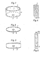
- the inner shell shown in Fig. 1 consists of two disc-shaped plastic films 1, 2, which preferably consist of polyethylene and which are welded at their edge to a cylindrical central part 4.
- a reinforced cylindrical filler neck 3 is welded into the lower film 2.
- Fig. 2 shows a similar inner shell, in which the two disc-shaped films 1 and 2 are welded together directly at the edge without a central part 4.
- Such an inner shell is particularly suitable for lining spherical containers.
- Fig. 3 shows a further inner shell, in which two octagonal foils are welded together at the edge.
- the folding technique according to the invention will be described below for the sake of simplicity with reference to the inner cover shown in FIG. 2.
- the folding takes place in such a way that the two disc-shaped film parts 1 and 2 are first placed on top of each other. Then both foils, starting from the filler neck 3, are folded evenly upwards from the edge, the middle part of the upper foil 1 remaining on the filler neck 3.
- a protective cover 5 closed at one end is then pulled over the inner cover folded in this way.
- This can for example consist of a plastic tube made of the same material, which can be welded, tied, knotted or open at the upper end 5A.
- the inner sleeve provided with this protective sleeve 5 can now, as shown in FIGS. 6 to 8, be introduced into a container 6 and filled.
- the container 6 shown is provided at the lower end with an outflow opening 6A and at the upper end with an opening 6B.
- the inner casing 1, 2 provided with the protective casing 5 is inserted into the container 6 through the lower opening 6A of the container 6. This can be done in such a way that by means of a cord, a band or a wire which has been passed through the upper opening 6B into the container 6 and the lower opening 6A, is fastened to the upper end 5A of the inner casing and this end thereafter the container 6 is pulled through until it is in or near the upper opening 6B of the container 6.
- the filler neck 3 is then fastened with a fitting in the lower container opening 6A.
- the protective cover 5 can then, as shown in FIG. 7, be removed immediately, as a result of which the inner cover unfolds in the manner shown in FIG. 7. If the filling process is then initiated, the inner casing 1, 2 lies against the wall of the container 6 and unfolds successively with the progress of the filling process.
Abstract
Description
Die Erfindung betrifft eine flexible Innenhülle mit einem Einfüllstutzen, an dem eine Armatur befestigbar ist, für die Auskleidung von Transport- oder Lagerbehältern, wobei die Innenhülle vor ihrer Einführung in den Behälter mit einer schlauchförmigen, abziehbaren Schutzhülle versehen ist.The invention relates to a flexible inner shell with a filler neck, to which a fitting can be fastened, for the lining of transport or storage containers, the inner shell being provided with a tubular, removable protective cover before it is introduced into the container.
Derartige Innenbehälter sind bekannt (DBP 29 00 998). Sie dienen der auswechselbaren, flüssigkeitsdichten Auskleidung von drucklosen oder unter Druck stehenden Behältern. Die bekannten Innenhüllen werden in der Weise gefaltet, daß sie am Einfüllstutzen und an der diesem gegenüberliegenden Stelle auseinandergezogen werden, so daß ein schlauchartiger, langgestreckter Körper entsteht. Dessen Endteil wird dann um 180° umgefaltet und die Innenhülle wird mit dem umgefalteten Ende zuerst in die Schutzhülle eingeführt. Eine derartig gefaltete Innenhülle hat den Nachteil, daß die Schutzhülle vor oder zu Beginn des Füllvorganges nicht abgezogen werden kann, da sonst ein unkontrolliertes Entfalten der Innenhülle auftritt und diese durch ungleichmäßige Spannung und Belastung reißen kann.Such inner containers are known (DBP 29 00 998). They are used for the interchangeable, liquid-tight lining of unpressurized or pressurized containers. The known inner sleeves are folded in such a way that they are pulled apart at the filler neck and at the point opposite this, so that a tubular, elongated body is produced. Its end part is then folded over by 180 ° and the inner cover is first inserted into the protective cover with the folded end. Such a folded inner cover has the disadvantage that the protective cover cannot be removed before or at the start of the filling process, since otherwise the inner cover will unfold in an uncontrolled manner and can tear due to uneven tension and stress.
Der Erfindung liegt die Aufgabe zugrunde, diesen Nachteil zu vermeiden und mittels einer besonderen Falttechnik zu erreichen, daß ein gleichmäßiger Füllvorgang gewährleistet wird.The invention has for its object to avoid this disadvantage and to achieve by means of a special folding technique that a uniform filling process is ensured.
Erfindungsgemäß wird dies dadurch erreicht, daß die Innenhülle vor der Einführung in die Schutzhülle in der Weise gefaltet wird, daß ihr dem Einfüllstutzen gegenüberliegender Teil auf diesem festgehalten und die Innenhülle dann von außen um eine in Richtung des Einfüllstutzen verlaufende Achse schirmförmig an diese herangefaltet wird.According to the invention, this is achieved in that the inner sleeve is folded before being introduced into the protective sleeve in such a way that the part opposite the filler neck is held thereon and the inner sleeve is then folded from the outside around an axis running in the direction of the filler neck in an umbrella-shaped manner.
Diese schirmartige Faltung bewirkt, daß nach dem Abziehen der Schutzhülle die Innenhülle weitgehend gleichmäßig radial nach außen fällt und ein gleichmäßiger und ungestörter Füllvorgang ermöglicht wird, der die Innenhülle an allen Stellen gleichmäßig belastet.This umbrella-like folding has the effect that, after the protective cover has been removed, the inner cover falls largely evenly radially outward and a uniform and undisturbed filling process is made possible which evenly loads the inner cover at all points.
Gemäß einer besonders vorteilhaften Ausbildung der Erfindung besteht die Innenhülle aus zwei, am Rande miteinander verschweißten Kunststoff-Folien von kreisrundem Querschnitt, von denen die eine mit einem zentralen Einfüllstutzen versehen ist. Die beiden kreisrunden Folien können an ihren Kanten auch über einen zylindrischen Teil miteinander verschweißt sein.According to a particularly advantageous embodiment of the invention, the inner shell consists of two plastic foils of circular cross section welded together at the edge, one of which is provided with a central filler neck. The edges of the two circular foils can also be welded to one another via a cylindrical part.
Die erfindungsgemäßen Innenhüllen können der Auskleidung beliebig geformter Behälter dienen, in die Flüssigkeiten eingefüllt werden und die darin drucklos oder unter Druck aufbewahrt werden. Der Druck kann hierbei durch inerte Gase wie Kohlendioxid oder Stickstoff erzeugt werden. Bevorzugt sind kugelförmige oder zylindrische Behälter. Jede andere Form ist möglich. Die erfindungsgemäße Innenhülle besteht aus flexiblem, gegen das einzufüllende Medium resistentem Kunststoff und kann ein- oder mehrschichtig aufgebaut sein. Für viele Zwecke ist Polyäthylen besonders geeignet. Der Einfüllstutzen besteht ebenfalls aus Kunststoff und ist in die Hülle eingeschweißt.The inner casings according to the invention can be used to line containers of any shape, into which liquids are poured and which are stored therein without pressure or under pressure. The pressure can be generated by inert gases such as carbon dioxide or nitrogen. Spherical or cylindrical containers are preferred. Any other shape is possible. The inner shell according to the invention consists of flexible plastic which is resistant to the medium to be filled in and can be constructed in one or more layers. Polyethylene is particularly suitable for many purposes. The filler neck is also made of plastic and is welded into the sleeve.
Weitere Einzelheiten und Vorteile der Erfindung können den in der Zeichnung dargestellten Ausführungsbeispielen entnommen werden.Further details and advantages of the invention can Embodiments shown in the drawing are taken.
Es zeigen:
- Fig. 1 bis 3 verschiedene Ausführungsformen einer Innenhülle;
- Fig. 4 die erfindungsgemäß zusammengefaltete Innenhülle;
- Fig. 5 Anordnung der nach Fig. 4 zusammengefalteten Innenhülle in einer Schutzhülle;
- Fig. 6 Anordnung der mit der Schutzhülle versehenen Innenhülle im Tank;
- Fig. 7 Abziehen der Schutzhülle;
- Fig. 8 Entfalten der Innenhülle.
- Fig. 1 to 3 different embodiments of an inner shell;
- 4 shows the inner shell folded according to the invention;
- 5 shows the arrangement of the inner sleeve folded according to FIG. 4 in a protective sleeve;
- 6 shows the arrangement of the inner sleeve provided with the protective sleeve in the tank;
- Fig. 7 removing the protective cover;
- Fig. 8 unfolding the inner shell.
Die in Fig. 1 dargestellte Innenhülle besteht aus zwei scheibenförmigen Kunststoff-Folien 1, 2, die vorzugsweise aus Polyäthylen bestehen und die an ihrer Kante mit einem zylindrischen Mittelteil 4 verschweißt sind. In die untere Folie 2 ist ein verstärkter zylindrischer Einfüllstutzen 3 eingeschweißt.The inner shell shown in Fig. 1 consists of two disc-shaped
Fig. 2 zeigt eine ähnliche Innenhülle, bei der die beiden scheibenförmigen Folien 1 und 2 ohne Mittelteil 4 am Rande direkt miteinander verschweißt sind. Eine solche Innenhülle eignet sich besonders zur Auskleidung kugelförmiger Behälter.Fig. 2 shows a similar inner shell, in which the two disc-
Fig. 3 zeigt eine weitere Innenhülle, bei der zwei achteckige Folien am Rande miteinander verschweißt sind.Fig. 3 shows a further inner shell, in which two octagonal foils are welded together at the edge.
Die erfindungsgemäße Falttechnik soll im folgenden der Einfachheit halber an Hand der in Fig. 2 dargestellten Innenhülle beschrieben werden. Die Faltung erfolgt hierbei in der Weise, daß die beiden scheibenförmigen Folienteile 1 und 2 zunächst aufeinander gelegt werden. Danach werden beide Folien, ausgehend vom Einfüllstutzen 3, vom Rande her gleichmäßig nach oben gefaltet, wobei der mittlere Teil der oberen Folie 1 auf dem Einfüllstutzen 3 liegen bleibt. Das Ergebnis dieser Falttechnik ist in Fig. 4 dargestellt. Danach wird über die so gefaltete Innenhülle eine an einem Ende geschlossene Schutzhülle 5 gezogen. Diese kann beispielsweise aus einem Kunststoffschlauch aus gleichem Material bestehen, welcher am oberen Ende 5A zugeschweißt, zugebunden, geknotet oder offen sein kann.The folding technique according to the invention will be described below for the sake of simplicity with reference to the inner cover shown in FIG. 2. The folding takes place in such a way that the two disc-
Die mit dieser Schutzhülle 5 versehene Innenhülle kann nunmehr, wie in den Figuren 6 bis 8 dargestellt, in einen Behälter 6 eingebracht und befüllt werden. Der dargestellte Behälter 6 ist am unteren Ende mit einer Ausflußöffnung 6A, am oberen Ende mit einer öffnung 6B versehen. Vor dem Befüllen wird die mit der Schutzhülle 5 versehene Innenhülle 1, 2 durch die untere öffnung 6A des Behälters 6 in den Behälter 6 eingeführt. Dies kann in der Weise geschehen, daß mittels einer Schnur, eines Bandes oder eines Drahtes, der durch die obere öffnung 6B in den Behälter 6 und die untere Öffnung 6A hindurchgeführt worden ist, am oberen Ende 5A der Innenhülle befestigt wird und dieses Ende danach durch den Behälter 6 hindurchgezogen wird, bis es sich in oder nahe der oberen öffnung 6B des Behälters 6 befindet. Der Einfüllstutzen 3 wird danach mit einer Armatur in der unteren Behälteröffnung 6A befestigt. Die Schutzhülle 5 kann dann, wie in Fig. 7 dargestellt, unmittelbar entfernt werden, wodurch sich die Innenhülle in der in Fig. 7 dargestellten Weise entfaltet. Wird dann der Befüllungsvorgang eingeleitet, so legt sich die Innenhülle 1, 2 an die Wand des Behälters 6 an und entfaltet sich sukzessive mit dem Fortschreiten des Füllungsvorganges.The inner sleeve provided with this
Claims (3)
Applications Claiming Priority (2)
| Application Number | Priority Date | Filing Date | Title |
|---|---|---|---|
| DE3218332 | 1982-05-14 | ||
| DE19823218332 DE3218332A1 (en) | 1982-05-14 | 1982-05-14 | FLEXIBLE INNER COVER FOR THE LINING OF TRANSPORT OR STORAGE CONTAINERS |
Publications (2)
| Publication Number | Publication Date |
|---|---|
| EP0094600A1 true EP0094600A1 (en) | 1983-11-23 |
| EP0094600B1 EP0094600B1 (en) | 1986-02-19 |
Family
ID=6163690
Family Applications (1)
| Application Number | Title | Priority Date | Filing Date |
|---|---|---|---|
| EP83104606A Expired EP0094600B1 (en) | 1982-05-14 | 1983-05-11 | Method to prepare a flexible inner bag for lining a transport or a storage container |
Country Status (2)
| Country | Link |
|---|---|
| EP (1) | EP0094600B1 (en) |
| DE (2) | DE3218332A1 (en) |
Cited By (4)
| Publication number | Priority date | Publication date | Assignee | Title |
|---|---|---|---|---|
| EP0303160A2 (en) * | 1987-08-04 | 1989-02-15 | Nittel Gmbh & Co. Kg | Method for folding an internal flexible lining for a cylindrical tank |
| EP0436841A2 (en) * | 1990-01-11 | 1991-07-17 | Sotralentz S.A. | Container assembly for the storage of liquid or powdery products |
| GB2395934A (en) * | 2002-11-22 | 2004-06-09 | Transfiguracion Vicente Salva | Procedure for filling flexible recipients |
| EP2474443A2 (en) | 2011-01-07 | 2012-07-11 | Huesker Synthetic GmbH | Cladding for silo container of a silo vehicle and method for inserting and positioning a cladding |
Citations (4)
| Publication number | Priority date | Publication date | Assignee | Title |
|---|---|---|---|---|
| US2991815A (en) * | 1957-08-01 | 1961-07-11 | Gen Tire & Rubber Co | Elastic bag for aerial delivery |
| FR1548386A (en) * | 1967-08-04 | 1968-12-06 | ||
| DE2900998A1 (en) * | 1979-01-12 | 1980-07-17 | Nittel Josef Kg | Sheath around collapsed flexible lining for rigid container - locates and gradually releases lining during filling with liquid from below to smooth out creases |
| DE2902291A1 (en) * | 1979-01-22 | 1980-07-24 | Bier Drive Ag | Polyethylene film sack for beer inside pressure vessel - is of two films below critical thickness for leakage |
-
1982
- 1982-05-14 DE DE19823218332 patent/DE3218332A1/en not_active Withdrawn
-
1983
- 1983-05-11 DE DE8383104606T patent/DE3362161D1/en not_active Expired
- 1983-05-11 EP EP83104606A patent/EP0094600B1/en not_active Expired
Patent Citations (4)
| Publication number | Priority date | Publication date | Assignee | Title |
|---|---|---|---|---|
| US2991815A (en) * | 1957-08-01 | 1961-07-11 | Gen Tire & Rubber Co | Elastic bag for aerial delivery |
| FR1548386A (en) * | 1967-08-04 | 1968-12-06 | ||
| DE2900998A1 (en) * | 1979-01-12 | 1980-07-17 | Nittel Josef Kg | Sheath around collapsed flexible lining for rigid container - locates and gradually releases lining during filling with liquid from below to smooth out creases |
| DE2902291A1 (en) * | 1979-01-22 | 1980-07-24 | Bier Drive Ag | Polyethylene film sack for beer inside pressure vessel - is of two films below critical thickness for leakage |
Cited By (8)
| Publication number | Priority date | Publication date | Assignee | Title |
|---|---|---|---|---|
| EP0303160A2 (en) * | 1987-08-04 | 1989-02-15 | Nittel Gmbh & Co. Kg | Method for folding an internal flexible lining for a cylindrical tank |
| EP0303160A3 (en) * | 1987-08-04 | 1990-01-31 | Nittel Gmbh & Co. Kg | Method for making an internal flexible lining for a cylindrical tank |
| EP0436841A2 (en) * | 1990-01-11 | 1991-07-17 | Sotralentz S.A. | Container assembly for the storage of liquid or powdery products |
| EP0436841A3 (en) * | 1990-01-11 | 1992-07-08 | Sotralentz S.A. | Container assembly for the storage of liquid or powdery products |
| GB2395934A (en) * | 2002-11-22 | 2004-06-09 | Transfiguracion Vicente Salva | Procedure for filling flexible recipients |
| GB2395934B (en) * | 2002-11-22 | 2006-08-09 | Vicente Salva Transfiguracion | Procedure for filling flexible recipients normally set on crate-type rigid or semi-rigid palletised receptacles and the set of devices |
| EP2474443A2 (en) | 2011-01-07 | 2012-07-11 | Huesker Synthetic GmbH | Cladding for silo container of a silo vehicle and method for inserting and positioning a cladding |
| DE102011002487A1 (en) | 2011-01-07 | 2012-07-12 | Huesker Synthetic Gmbh | Silo tank liner of a silo truck and method of loading and positioning a liner |
Also Published As
| Publication number | Publication date |
|---|---|
| DE3362161D1 (en) | 1986-03-27 |
| EP0094600B1 (en) | 1986-02-19 |
| DE3218332A1 (en) | 1983-11-17 |
Similar Documents
| Publication | Publication Date | Title |
|---|---|---|
| US4586628A (en) | Resilient inner liner for lining of transport or storage containers | |
| DE2544491A1 (en) | LID BARREL | |
| DE102010049028A1 (en) | Method for attaching a carrying handle and application head for carrying out the method | |
| DE2953071A1 (en) | Container for filling liquid | |
| EP0098322A1 (en) | Plastic bag | |
| EP0094600B1 (en) | Method to prepare a flexible inner bag for lining a transport or a storage container | |
| DE1411552A1 (en) | Container | |
| DE2231318A1 (en) | CONTAINER MADE OF FLEXIBLE MATERIAL WITH CLOSURE | |
| CH709803A2 (en) | Changeable volume for storage and transport. | |
| EP0303160B1 (en) | Method for folding an internal flexible lining for a cylindrical tank | |
| DE1602425B1 (en) | Process for lining a rigid container and lining for carrying out the process | |
| DE2736272A1 (en) | PROCEDURE FOR FILLING A FILM BAG IN A PRESSURE TANK WITH A BEVERAGE CONTAINING CARBON, IN PARTICULAR BEER | |
| DE3815641A1 (en) | Closable container for used tennis balls | |
| DE2342193A1 (en) | CONTAINER FOR FILLING LIQUIDS | |
| CH399297A (en) | Packaging made of thermoplastic hose or film material, which is provided with a spout | |
| EP0372173A2 (en) | Flexible lining for vats, drums and like hard packagings | |
| DE1034098B (en) | Gas-tight, collapsible pressurized container for the shipping of synthetic resin | |
| DE3839697A1 (en) | Method for producing a flexible internal wrapping for containers | |
| DE1411551A1 (en) | Collapsible container | |
| DE6604383U (en) | SILO FOR THE STORAGE OF LITTLE, GRAINY OR SIMILAR GOODS | |
| AT201462B (en) | Liquid displacers | |
| AT242053B (en) | Cylindrical container made by blowing synthetic thermoplastic material for liquids which decompose with gas evolution | |
| DE1761811C (en) | Carrying device for a collapsible, sack-like, cylindrical container | |
| DE19643669A1 (en) | Process container for high pressure treatment of liquid products | |
| DE1251212B (en) | Flexible transport container with carrying device |
Legal Events
| Date | Code | Title | Description |
|---|---|---|---|
| PUAI | Public reference made under article 153(3) epc to a published international application that has entered the european phase |
Free format text: ORIGINAL CODE: 0009012 |
|
| AK | Designated contracting states |
Designated state(s): BE CH DE FR GB IT LI NL |
|
| 17P | Request for examination filed |
Effective date: 19830927 |
|
| GRAA | (expected) grant |
Free format text: ORIGINAL CODE: 0009210 |
|
| AK | Designated contracting states |
Kind code of ref document: B1 Designated state(s): BE CH DE FR GB IT LI NL |
|
| RAP1 | Party data changed (applicant data changed or rights of an application transferred) |
Owner name: NITTEL GMBH & CO. KG |
|
| REF | Corresponds to: |
Ref document number: 3362161 Country of ref document: DE Date of ref document: 19860327 |
|
| ITF | It: translation for a ep patent filed |
Owner name: STUDIO JAUMANN |
|
| ET | Fr: translation filed | ||
| PLBE | No opposition filed within time limit |
Free format text: ORIGINAL CODE: 0009261 |
|
| STAA | Information on the status of an ep patent application or granted ep patent |
Free format text: STATUS: NO OPPOSITION FILED WITHIN TIME LIMIT |
|
| 26N | No opposition filed | ||
| PGFP | Annual fee paid to national office [announced via postgrant information from national office to epo] |
Ref country code: NL Payment date: 19870531 Year of fee payment: 5 |
|
| PGFP | Annual fee paid to national office [announced via postgrant information from national office to epo] |
Ref country code: FR Payment date: 19890414 Year of fee payment: 7 |
|
| PG25 | Lapsed in a contracting state [announced via postgrant information from national office to epo] |
Ref country code: GB Effective date: 19890511 |
|
| PG25 | Lapsed in a contracting state [announced via postgrant information from national office to epo] |
Ref country code: NL Effective date: 19891201 |
|
| GBPC | Gb: european patent ceased through non-payment of renewal fee | ||
| NLV4 | Nl: lapsed or anulled due to non-payment of the annual fee | ||
| PG25 | Lapsed in a contracting state [announced via postgrant information from national office to epo] |
Ref country code: FR Effective date: 19910131 |
|
| REG | Reference to a national code |
Ref country code: FR Ref legal event code: ST |
|
| PGFP | Annual fee paid to national office [announced via postgrant information from national office to epo] |
Ref country code: BE Payment date: 19910419 Year of fee payment: 9 |
|
| PGFP | Annual fee paid to national office [announced via postgrant information from national office to epo] |
Ref country code: CH Payment date: 19910826 Year of fee payment: 9 |
|
| PG25 | Lapsed in a contracting state [announced via postgrant information from national office to epo] |
Ref country code: LI Effective date: 19920531 Ref country code: CH Effective date: 19920531 Ref country code: BE Effective date: 19920531 |
|
| BERE | Be: lapsed |
Owner name: NITTEL G.M.B.H. & CO. K.G. Effective date: 19920531 |
|
| REG | Reference to a national code |
Ref country code: CH Ref legal event code: PL |
|
| PGFP | Annual fee paid to national office [announced via postgrant information from national office to epo] |
Ref country code: DE Payment date: 19940131 Year of fee payment: 11 |
|
| PG25 | Lapsed in a contracting state [announced via postgrant information from national office to epo] |
Ref country code: DE Effective date: 19950201 |