EP0093570B1 - Boiler systems - Google Patents
Boiler systems Download PDFInfo
- Publication number
- EP0093570B1 EP0093570B1 EP83302363A EP83302363A EP0093570B1 EP 0093570 B1 EP0093570 B1 EP 0093570B1 EP 83302363 A EP83302363 A EP 83302363A EP 83302363 A EP83302363 A EP 83302363A EP 0093570 B1 EP0093570 B1 EP 0093570B1
- Authority
- EP
- European Patent Office
- Prior art keywords
- tubes
- economiser
- header
- superheater
- boiler
- Prior art date
- Legal status (The legal status is an assumption and is not a legal conclusion. Google has not performed a legal analysis and makes no representation as to the accuracy of the status listed.)
- Expired
Links
Images
Classifications
-
- F—MECHANICAL ENGINEERING; LIGHTING; HEATING; WEAPONS; BLASTING
- F22—STEAM GENERATION
- F22B—METHODS OF STEAM GENERATION; STEAM BOILERS
- F22B21/00—Water-tube boilers of vertical or steeply-inclined type, i.e. the water-tube sets being arranged vertically or substantially vertically
- F22B21/34—Water-tube boilers of vertical or steeply-inclined type, i.e. the water-tube sets being arranged vertically or substantially vertically built-up from water tubes grouped in panel form surrounding the combustion chamber, i.e. radiation boilers
- F22B21/36—Water-tube boilers of vertical or steeply-inclined type, i.e. the water-tube sets being arranged vertically or substantially vertically built-up from water tubes grouped in panel form surrounding the combustion chamber, i.e. radiation boilers involving an upper drum or headers mounted at the top of the combustion chamber
-
- F—MECHANICAL ENGINEERING; LIGHTING; HEATING; WEAPONS; BLASTING
- F22—STEAM GENERATION
- F22B—METHODS OF STEAM GENERATION; STEAM BOILERS
- F22B37/00—Component parts or details of steam boilers
- F22B37/02—Component parts or details of steam boilers applicable to more than one kind or type of steam boiler
- F22B37/48—Devices or arrangements for removing water, minerals or sludge from boilers ; Arrangement of cleaning apparatus in boilers; Combinations thereof with boilers
-
- F—MECHANICAL ENGINEERING; LIGHTING; HEATING; WEAPONS; BLASTING
- F22—STEAM GENERATION
- F22B—METHODS OF STEAM GENERATION; STEAM BOILERS
- F22B21/00—Water-tube boilers of vertical or steeply-inclined type, i.e. the water-tube sets being arranged vertically or substantially vertically
- F22B21/34—Water-tube boilers of vertical or steeply-inclined type, i.e. the water-tube sets being arranged vertically or substantially vertically built-up from water tubes grouped in panel form surrounding the combustion chamber, i.e. radiation boilers
- F22B21/341—Vertical radiation boilers with combustion in the lower part
- F22B21/343—Vertical radiation boilers with combustion in the lower part the vertical radiation combustion chamber being connected at its upper part to a sidewards convection chamber
- F22B21/345—Vertical radiation boilers with combustion in the lower part the vertical radiation combustion chamber being connected at its upper part to a sidewards convection chamber with a tube bundle between an upper and a lower drum in the convection pass
-
- F—MECHANICAL ENGINEERING; LIGHTING; HEATING; WEAPONS; BLASTING
- F22—STEAM GENERATION
- F22B—METHODS OF STEAM GENERATION; STEAM BOILERS
- F22B31/00—Modifications of boiler construction, or of tube systems, dependent on installation of combustion apparatus; Arrangements or dispositions of combustion apparatus
- F22B31/04—Heat supply by installation of two or more combustion apparatus, e.g. of separate combustion apparatus for the boiler and the superheater respectively
- F22B31/045—Steam generators specially adapted for burning refuse
-
- F—MECHANICAL ENGINEERING; LIGHTING; HEATING; WEAPONS; BLASTING
- F22—STEAM GENERATION
- F22B—METHODS OF STEAM GENERATION; STEAM BOILERS
- F22B37/00—Component parts or details of steam boilers
- F22B37/02—Component parts or details of steam boilers applicable to more than one kind or type of steam boiler
- F22B37/10—Water tubes; Accessories therefor
- F22B37/14—Supply mains, e.g. rising mains, down-comers, in connection with water tubes
- F22B37/148—Tube arrangements for the roofs
-
- F—MECHANICAL ENGINEERING; LIGHTING; HEATING; WEAPONS; BLASTING
- F22—STEAM GENERATION
- F22D—PREHEATING, OR ACCUMULATING PREHEATED, FEED-WATER FOR STEAM GENERATION; FEED-WATER SUPPLY FOR STEAM GENERATION; CONTROLLING WATER LEVEL FOR STEAM GENERATION; AUXILIARY DEVICES FOR PROMOTING WATER CIRCULATION WITHIN STEAM BOILERS
- F22D1/00—Feed-water heaters, i.e. economisers or like preheaters
- F22D1/02—Feed-water heaters, i.e. economisers or like preheaters with water tubes arranged in the boiler furnaces, fire tubes or flue ways
- F22D1/04—Feed-water heaters, i.e. economisers or like preheaters with water tubes arranged in the boiler furnaces, fire tubes or flue ways the tubes having plain outer surfaces, e.g. in vertical arrangement
-
- F—MECHANICAL ENGINEERING; LIGHTING; HEATING; WEAPONS; BLASTING
- F22—STEAM GENERATION
- F22G—SUPERHEATING OF STEAM
- F22G7/00—Steam superheaters characterised by location, arrangement, or disposition
- F22G7/14—Steam superheaters characterised by location, arrangement, or disposition in water-tube boilers, e.g. between banks of water tubes
-
- F—MECHANICAL ENGINEERING; LIGHTING; HEATING; WEAPONS; BLASTING
- F23—COMBUSTION APPARATUS; COMBUSTION PROCESSES
- F23J—REMOVAL OR TREATMENT OF COMBUSTION PRODUCTS OR COMBUSTION RESIDUES; FLUES
- F23J3/00—Removing solid residues from passages or chambers beyond the fire, e.g. from flues by soot blowers
- F23J3/02—Cleaning furnace tubes; Cleaning flues or chimneys
- F23J3/023—Cleaning furnace tubes; Cleaning flues or chimneys cleaning the fireside of watertubes in boilers
-
- F—MECHANICAL ENGINEERING; LIGHTING; HEATING; WEAPONS; BLASTING
- F28—HEAT EXCHANGE IN GENERAL
- F28G—CLEANING OF INTERNAL OR EXTERNAL SURFACES OF HEAT-EXCHANGE OR HEAT-TRANSFER CONDUITS, e.g. WATER TUBES OR BOILERS
- F28G7/00—Cleaning by vibration or pressure waves
-
- Y—GENERAL TAGGING OF NEW TECHNOLOGICAL DEVELOPMENTS; GENERAL TAGGING OF CROSS-SECTIONAL TECHNOLOGIES SPANNING OVER SEVERAL SECTIONS OF THE IPC; TECHNICAL SUBJECTS COVERED BY FORMER USPC CROSS-REFERENCE ART COLLECTIONS [XRACs] AND DIGESTS
- Y02—TECHNOLOGIES OR APPLICATIONS FOR MITIGATION OR ADAPTATION AGAINST CLIMATE CHANGE
- Y02E—REDUCTION OF GREENHOUSE GAS [GHG] EMISSIONS, RELATED TO ENERGY GENERATION, TRANSMISSION OR DISTRIBUTION
- Y02E20/00—Combustion technologies with mitigation potential
- Y02E20/12—Heat utilisation in combustion or incineration of waste
Definitions
- This invention relates to boiler systems and particularly, but not exclusively, to boiler systems for furnaces which are capable of burning, in addition to conventional fuel, municipal solid waste or kraft black liquor of the paper industry.
- Such boiler systems may include a superheater and an economiser in a convection pass downstream of a combustion chamber.
- An additional boiler assembly may also be provided between the superheater and the economiser. It is known to provide a plurality of steam and water drums, which, in particular, are connected to steam generating tubes for receiving a steam/water mixture and separating the mixture into a steam supply and a water supply.
- German Patent Application Publication No. DE-A-3 022 880 discloses a single drum all-welded boiler system for a furnace having a combustion chamber and a convection pass downstream of the combustion chamber and connected to the combustion chamber in a transition area, the system comprising:
- US Patent Specification No. US-A-2 893 829 discloses a boiler disposed in the convection pass between an economiser and a superheater.
- the boiler is made up of banks of tubes welded at the bottom to a common inlet header and at the top to a common outlet header.
- the economiser is likewise made up of banks of tubes, both boiler and economiser tubes extending vertically for upward flow of fluid.
- Preferred embodiments of the present invention described hereinbelow provide boiler systems and furnaces which have various improved characteristics and are particularly suited for the burning of waste fuels such as municipal solid waste and kraft liquors.
- the preferred embodiments utilise a single steam drum which, in addition, can be positioned out of high temperature areas of the system and thus be exposed to a less dangerous environment.
- the use of a single drum facilitates the shop assembly of welded tube modules for a boiler and/or economiser of the boiler system or steam generating unit. This reduces on-site work necessary in erecting the facility. This is contrasted to the prior art where tubes are expanded at the top and bottom to separate steam and water drums which, themselves, are in the hot gas stream.
- the single drum employed in the preferred embodiments has forged steel connections which do not require the rolling and seal welding that is required in the prior art connection of steam and water drums to heat transfer tubes.
- the superheater of the preferred embodiments is designed with multiple steam flow paths with high steam mass flow to provide protection against overheating of the tubes.
- the smaller boiler module cross-section also permits extension of the superheater surface into areas previously occupied by the type of boiler banks utilising two steam and water drums.
- Boiler and economiser modules of the preferred embodiments are designed for the upflow of fluid at all times.
- the ends of a lower header of the boiler module are provided with flanged sections which permit examination for potential deposition of contaminants in the saturated water circuit.
- the prior art two-drum designs are based on a downflow of water in several of the rear boiler tube rows which act as downcomers and an upflow in the remaining tube sections.
- An improved arch construction in the furnace chamber is also provided, in the preferred embodiments, in the upper region of the furnace and below the superheater.
- the superheater tubes are provided with a rapper or rapping means or device for dislodging soot and ash from the tubes, with the advantageous retention of a small amount of ash to reduce corrosion of the tubes.
- a rapper or rapping means or device for dislodging soot and ash from the tubes, with the advantageous retention of a small amount of ash to reduce corrosion of the tubes.
- the preferred embodiments provide a single drum boiler system and a furnace having a combustion chamber and a convection pass connected through a transition area to the combustion chamber, comprising a superheater disposed in the transition area, an economiser disposed in the convection pass and a single steam drum having inlets and outlets connected to the economiser and superheater.
- a boiler tube assembly is arranged between the economiser and the superheater in the convection pass with both the boiler and economiser being fed from below for an upward flow of fluid therethrough, an arch member is provided in the combustion chamber for improved gas flow and temperature distribution entering the superheater, and elongate vertical heat transfer surface is provided to facilitate cleaning and disposal of deposits.
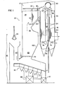
- Figure 1 shows a one drum boiler system 10 and a furnace 20.
- the furnace 20 includes combustion means which is capable of burning various fuels.
- the combustion means 30 is arranged to burn municipal solid waste which is supplied, for example, by a grapple 40 which transfers the municipal solid waste from a bin 41 into a chute 42 from which it is transferred to combustion means in the form of a stoker 30.
- the stoker 30 is provided, in known fashion, with air supply means 32 for igniting and burning the waste.
- the furnace 20 includes a combustion chamber 22 having a lower end which receives overfire air via a supply means 24.
- a convection pass 26 downstream of the combustion chamber 22 includes an exhaust gas outlet 34 which, in known fashion, may be connected to pollution control equipment and/or a stack.
- the furnace also includes a quenching basin 44 which receives molten unburned material.
- the convection pass 26 includes a plurality of baffle walls 54 for directing the exhaust gases in a serpentine path through the convection pass.
- collection hoppers 56 may be provided for collecting soot at the bottom of the convection pass 26.
- the boiler system 10 includes an economiser or economiser module 70 disposed in the convection pass 26. Water is supplied to a bottom inlet header 74 of the economiser 70.
- the economiser 70 comprises a module of heat transfer tubes which will be described later in greater detail. Water flow is upward through the tubes to an outlet header 68 and thence to a drum 90.
- Water from the drum 90 is fed through a downcomer 76 to supply lower furnace wall headers and to supply a generating bank or boiler generating module 72 through a lower header 78. Fluid flow is upward through the tubes to an upper header 80 and thence to the drum 90.
- the boiler system 10 also comprises a superheater 60 composed of multiple tube sections interconnecting front and rear headers 64 and 62, respectively.
- a superheater 60 composed of multiple tube sections interconnecting front and rear headers 64 and 62, respectively.
- steam enters a centre section of the front header 64 through multiple connections 61 from the steam drum 90. Steam then flows rearwardly, as indicated by arrows 63, in the direction of gas flow, which is indicated by an arrow 73, and enters a centre section of the rear header 62.
- Multiple external connections 65 then conduct the steam to a side section of the front header 64 from which the flow is again rearward, as indicated by arrows 67, entering a side section of the rear header 62.
- Flow is then through external piping to an attemperator 66 and then to an opposite side section of the front header 64. Flow is then again rearward, as indicated by arrows 69, to the rear header 62 from which it exits to a point of use as indicated by an
- rapping means 100 is provided for rapping the tubes of the superheater 60 to free the tubes of undesirable deposits. Such rapping means is particularly advantageous where municipal solid waste is to be burned, due to its high content of impurities.
- the rapping means 100 is more fully described later.
- the combustion chamber 22 of the furnace 20 is provided with a first arch structure 102 to improve combustion characteristics in the zone immediately above the stoker 30.
- a second arch structure 104 is provided in the transition area 28 below the superheater 60 for improved gas flow and gas temperature distribution through the superheater.
- the illustrated system is distinct from prior approaches to furnace and boiler design of this type in that no superheater screen is provided in the combustion chamber 22.
- the long flow economiser 70 and boiler generating modules 72 are unique in application to a unit designed for municipal solid waste disposal. Moreover, the large furnace 20 eliminates the need for screen tubes or boiler surface ahead of the superheater 60.
- the positioning of the steam drum 90 in a remote area above the convection pass 26 and not exposed to combustion gas flow also permits the use of all-welded shop assembled modular tube arrangements for the economiser 70 and generating bank 72.
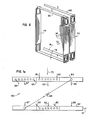
- the economiser module 70 and boiler generating module 72 are of duplicate design.
- the tubes 114 are 51 mm (2 inches) in outside diameter and are welded to both the top and bottom headers.
- the vertical runs of the tubes 114 have a back spacing of 190 mm (7.5 inches), and 63 mm (2.5 inches) wide fins are welded on each side of tubes along the vertical run with a 13 mm (0.5 inch) gap between fins.
- Any desired number of duplicate modules can be provided in the appropriate part of the convection pass, to provide a boiler bank or economiser as needed to suit job requirements.
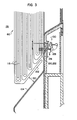
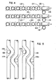
- FIGs 3, 4 and 5 show details of the superheater tube rapping means 100.
- rows of tubes 118 are provided with aligned lugs 120, 122, only one pair being illustrated.
- each tube 118 includes a rearwardly facing lug 120 and a forwardly facing lug 122.
- Each rearwardly facing lug 120 of one tube 118 is engaged with and abuts a forwardly facing lug 122 of an adjacenttube 118.
- On a rearmost tube 118a there is provided an impact body 124 which is larger than the lugs 120, 122 and arranged to receive an impact from a ram 126.
- Each row of tubes 118 is provided with its own set of lugs and impact body, with the lugs and impact bodies of one row being offset in a vertical direction with respect to those of an adjacent row to facilitate the rapping of every row of tubes.
- An outer and thus accessible set of tubes 119 is provided without bosses or an impact body and is curved, as shown in Figure 5, to expose the underlying impact bodies 124 to the rams 126.
- the rams 126 can be reciprocated in the direction of arrows 128 to the impact bodies 124 by any suitable means as illustrated and described in connection with Figure 7.
- Access to the rams 126 is provided from the rear of the superheater 60. It has been found that the use of a rapping operation to dislodge soot and foreign matter from the tubes 118 advantageously leaves on the tubes a thin film of ash which acts as a corrosion resisting agent.
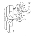
- the rapping means 100 comprises a shaft 154 which can be rotated relatively slowly and which carries one or more hammers 156.
- Each hammer 156 is connected at a pivot connection 158 to an arm connected to the shaft 154. With rotation of the shaft 154, the pivot connection 158 moves in a circular path 160.
- Each hammer 156 having a hammer arm 162, moves sequentially into a series of positions shown at 156a to 156g. At the position 156g, the hammer has just struck a ram 126. At the position 156a, the hammer passes a support 164 which slidable receives a ram 126. In the positions 156b and 156c, the hammer hangs free. In the position 156d, the hammer is rotated, with the aid of its arm 162, about and over the top of the shaft 154. At the position 156f, the hammer is shown in free fall an instant before it strikes the ram 126.
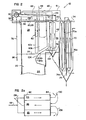
- FIGS 2 and 2a in which similar reference numerals are utilised to designate similar parts, . partially show a boiler system for a kraft recovery unit which burns kraft liquor as fuel.
- a lower furnace for burning kraft liquor is similar to a unit shown and described in our US Patent No. 2 893 829 (J.E. Hutton).
- the unit is also adaptable for use as a power boiler burning coal, gas or oil with modifications to the lower furnace.
- Such units are used in the pulp and paper industry for the generation of steam used in the pulping process.
- the kraft recovery unit of Figure 2 requires special considerations.
- FIG. 2a is a schematic top view of roof tubes of the furnace.
- An economiser inlet header 74 supplies water to the bottom of a first stage economiser 70. Water flow is upward in the module and then downward through external lines 76a to a lower header74a of a second stage economiser 70a. Water flow is again upward in the module and then through a line 81 to the steam drum 90.
- Water is supplied from the steam drum 90 to two downcomers 76, only one of which is shown.
- the downcomers 76 are not exposed to combustion gas and supply water through a line 77 to a lower header 78 of boiler modules 46, which are disposed in the convection pass 26 between the superheater 60 and the economisers 70 and 70a. Fluid flow is upward in the boiler modules 46 and is delivered over a line 48 to the steam drum 90.
- water is also provided to lower wall headers of the furnace (not shown). Water and steam rise through the furnace walis and are discharged to upper wall headers and thence through risers to the steam drum 90.
- steam is supplied to a primary superheater 60a from the centre of the front roof header 82 th roug h connecting tubes 138. From the primary superheater 60a the steam flows through the attemperator 66 and then through a secondary superheater 60b, exiting through a line 88 to a point of use.
- the boiler and economiser modules can be arranged as single or multiple units.
- the features of permitting the use of any required number of modules and the ability to vary the division between boiler and economiser heating surface gives the designer new flexibility-it permits the optimising of surface division as a function of operating pressure and avoids an undesirabie steaming economiser.
- the economiser and boiler consist of shop-assembled, welded modules as illustrated in Figure 6.
- the arch member 104 for the superheaters can be designed with an upstream section 104a which has been found advantageously to be inclined at about 50° to the horizontal and a downstream section 104b which has been found advantageously to be inclined at about 30° to the horizontal for gas flow and temperature distribution through the superheater 60.
Landscapes
- Engineering & Computer Science (AREA)
- Mechanical Engineering (AREA)
- General Engineering & Computer Science (AREA)
- Chemical & Material Sciences (AREA)
- Combustion & Propulsion (AREA)
- Physics & Mathematics (AREA)
- Thermal Sciences (AREA)
- Control Of Steam Boilers And Waste-Gas Boilers (AREA)
- Incineration Of Waste (AREA)
- Fluidized-Bed Combustion And Resonant Combustion (AREA)
Description
- This invention relates to boiler systems and particularly, but not exclusively, to boiler systems for furnaces which are capable of burning, in addition to conventional fuel, municipal solid waste or kraft black liquor of the paper industry. Such boiler systems may include a superheater and an economiser in a convection pass downstream of a combustion chamber. An additional boiler assembly may also be provided between the superheater and the economiser. It is known to provide a plurality of steam and water drums, which, in particular, are connected to steam generating tubes for receiving a steam/water mixture and separating the mixture into a steam supply and a water supply.
- German Patent Application Publication No. DE-A-3 022 880 discloses a single drum all-welded boiler system for a furnace having a combustion chamber and a convection pass downstream of the combustion chamber and connected to the combustion chamber in a transition area, the system comprising:
- a superheater disposed in the transition area and having an inlet and an outlet;
- an economiser disposed in the convection pass and having an inlet and an outlet;
- a boiler disposed in the convection pass between the economiser and the superheater; and
- a single steam drum having at least one inlet connected to the economiser outlet and at least one outlet connected to the superheater inlet, the drum being located in an area not exposed to combustion gas flow.
- Particular problems occur when dealing with boiler systems for burning kraft liquors and solid waste in that inordinate amounts of soot and other impurities are generated which tend to foul heat transfer tubing of the superheaters, boilers and economisers.
- Particularly in view of rising energy costs, it has become increasingly interesting to utilise such wastes to generate steam. This interest has resulted in the demand for higher steam pressures and temperatures with extended superheater control ranges.
- In addition to the fouling problems in burning kraft liquors, water can leak into the smelt bed formed at the bottom of the furnace chamber, which can cause severe explosion and fire problems due to smelt-water reactions. Close quality control is thus required in the manufacture and construction of pressure parts for such boiler systems.
- Another problem arises, in particular, with the burning of municipal solid wastes, in that excess soot and ash material must be dislodged from tubes of heat transfer surface.
- US Patent Specification No. US-A-2 893 829 discloses a boiler disposed in the convection pass between an economiser and a superheater. The boiler is made up of banks of tubes welded at the bottom to a common inlet header and at the top to a common outlet header. The economiser is likewise made up of banks of tubes, both boiler and economiser tubes extending vertically for upward flow of fluid.
- According to the invention there is provided a single drum all-welded boiler system for a furnace having a combustion chamber and a convection pass downstream of the combustion chamber and connected to the combustion chamber in a transition area, the system comprising:
- a superheater disposed in the transition area and having an inlet and an outlet;
- an economiser disposed in the convection pass and having an inlet and an outlet;
- a boiler disposed in the convection pass between the economiser and the superheater; and
- a single steam drum having at least one inlet connected to the economiser outlet and at least one outlet connected to the superheater inlet, the drum being located in an area not exposed to combustion gas flow;
characterised in that:- the boiler comprises at least one modular unit made up of a plurality of tubes welded at the bottom to a common inlet header and at the top to a common outlet header;
- the economiser comprises at least one modular unit made up of a plurality of tubes;
- the tubes in both boiler and economiser modular units are finned and extend vertically for upward flow of fluid; and
- the boiler modular unit and the economiser modular unit are of duplicate design.
- Preferred embodiments of the present invention described hereinbelow provide boiler systems and furnaces which have various improved characteristics and are particularly suited for the burning of waste fuels such as municipal solid waste and kraft liquors.
- The preferred embodiments utilise a single steam drum which, in addition, can be positioned out of high temperature areas of the system and thus be exposed to a less dangerous environment. In addition, the use of a single drum facilitates the shop assembly of welded tube modules for a boiler and/or economiser of the boiler system or steam generating unit. This reduces on-site work necessary in erecting the facility. This is contrasted to the prior art where tubes are expanded at the top and bottom to separate steam and water drums which, themselves, are in the hot gas stream.
- The single drum employed in the preferred embodiments has forged steel connections which do not require the rolling and seal welding that is required in the prior art connection of steam and water drums to heat transfer tubes.
- The superheater of the preferred embodiments is designed with multiple steam flow paths with high steam mass flow to provide protection against overheating of the tubes. The smaller boiler module cross-section also permits extension of the superheater surface into areas previously occupied by the type of boiler banks utilising two steam and water drums.
- Boiler and economiser modules of the preferred embodiments are designed for the upflow of fluid at all times. The ends of a lower header of the boiler module are provided with flanged sections which permit examination for potential deposition of contaminants in the saturated water circuit. The prior art two-drum designs are based on a downflow of water in several of the rear boiler tube rows which act as downcomers and an upflow in the remaining tube sections.
- An improved arch construction in the furnace chamber is also provided, in the preferred embodiments, in the upper region of the furnace and below the superheater.
- According to another feature of the preferred embodiments, the superheater tubes are provided with a rapper or rapping means or device for dislodging soot and ash from the tubes, with the advantageous retention of a small amount of ash to reduce corrosion of the tubes. A single drum all-welded boiler system dealing with these features is the subject-matter of divisional application EP-A-0254 379.
- Succinctly, the preferred embodiments provide a single drum boiler system and a furnace having a combustion chamber and a convection pass connected through a transition area to the combustion chamber, comprising a superheater disposed in the transition area, an economiser disposed in the convection pass and a single steam drum having inlets and outlets connected to the economiser and superheater.
- In the preferred embodiments, a boiler tube assembly is arranged between the economiser and the superheater in the convection pass with both the boiler and economiser being fed from below for an upward flow of fluid therethrough, an arch member is provided in the combustion chamber for improved gas flow and temperature distribution entering the superheater, and elongate vertical heat transfer surface is provided to facilitate cleaning and disposal of deposits.
- The invention will now be further described, by way of illustrative and non-limiting example, with reference to the accompanying drawings, in which.
- Figure 1 is an outline of a one-drum boiler system embodying the invention;
- Figure 1a is a schematic top view showing a steam flow path of a superheater used in the embodiment of Figure I;
- Figure 2 is a view similar to Figure 1 of a different one-drum boiler system
- Figure 2a is a schematic top view of a roof tube arrangement used in the embodiment of Figure I;
- Figure 3 is a partial side view of a superheater of the boiler system, showing rapping means used to dislodge soot and ash;
- Figure 4 is a plan view of the rapping means along a line 4-4 of Figure 3;
- Figure 5 is a rear view of the rapping means along a line 5-5 of Figure 3;
- Figure 6 is a perspective view showing tube modules used for an economiser and boiler of a system embodying the invention; and
- Figure 7 is an enlarged side elevational view showing a preferred embodiment of the rapping means.
- Referring to the drawings, Figure 1 shows a one
drum boiler system 10 and afurnace 20. Thefurnace 20 includes combustion means which is capable of burning various fuels. In the embodiment shown the combustion means 30 is arranged to burn municipal solid waste which is supplied, for example, by agrapple 40 which transfers the municipal solid waste from abin 41 into achute 42 from which it is transferred to combustion means in the form of astoker 30. Thestoker 30 is provided, in known fashion, with air supply means 32 for igniting and burning the waste. Thefurnace 20 includes acombustion chamber 22 having a lower end which receives overfire air via a supply means 24. Aconvection pass 26 downstream of thecombustion chamber 22 includes anexhaust gas outlet 34 which, in known fashion, may be connected to pollution control equipment and/or a stack. - In the case where municipal solid waste is to be burned, the furnace also includes a
quenching basin 44 which receives molten unburned material. - Hot gases produced in the
combustion chamber 22 rise in the direction of anarrow 52 through atransition area 28, where the combustion chamber is connected to theconvection pass 26, and into the convection pass. In the embodiment shown, theconvection pass 26 includes a plurality ofbaffle walls 54 for directing the exhaust gases in a serpentine path through the convection pass. Thus,collection hoppers 56 may be provided for collecting soot at the bottom of theconvection pass 26. - The
boiler system 10 includes an economiser oreconomiser module 70 disposed in theconvection pass 26. Water is supplied to abottom inlet header 74 of theeconomiser 70. Theeconomiser 70 comprises a module of heat transfer tubes which will be described later in greater detail. Water flow is upward through the tubes to anoutlet header 68 and thence to adrum 90. - Water from the
drum 90 is fed through adowncomer 76 to supply lower furnace wall headers and to supply a generating bank orboiler generating module 72 through alower header 78. Fluid flow is upward through the tubes to anupper header 80 and thence to thedrum 90. - The
boiler system 10 also comprises asuperheater 60 composed of multiple tube sections interconnecting front andrear headers front header 64 through multiple connections 61 from thesteam drum 90. Steam then flows rearwardly, as indicated byarrows 63, in the direction of gas flow, which is indicated by anarrow 73, and enters a centre section of therear header 62. Multipleexternal connections 65 then conduct the steam to a side section of thefront header 64 from which the flow is again rearward, as indicated byarrows 67, entering a side section of therear header 62. Flow is then through external piping to anattemperator 66 and then to an opposite side section of thefront header 64. Flow is then again rearward, as indicated byarrows 69, to therear header 62 from which it exits to a point of use as indicated by anarrow 71. - Referring again to Figure 1, rapping means 100 is provided for rapping the tubes of the
superheater 60 to free the tubes of undesirable deposits. Such rapping means is particularly advantageous where municipal solid waste is to be burned, due to its high content of impurities. The rapping means 100 is more fully described later. - The
combustion chamber 22 of thefurnace 20 is provided with a firstarch structure 102 to improve combustion characteristics in the zone immediately above thestoker 30. A secondarch structure 104 is provided in thetransition area 28 below thesuperheater 60 for improved gas flow and gas temperature distribution through the superheater. In addition to the fact that only asingle steam drum 90 is used, the illustrated system is distinct from prior approaches to furnace and boiler design of this type in that no superheater screen is provided in thecombustion chamber 22. - The
long flow economiser 70 andboiler generating modules 72 are unique in application to a unit designed for municipal solid waste disposal. Moreover, thelarge furnace 20 eliminates the need for screen tubes or boiler surface ahead of thesuperheater 60. - The positioning of the
steam drum 90 in a remote area above theconvection pass 26 and not exposed to combustion gas flow also permits the use of all-welded shop assembled modular tube arrangements for theeconomiser 70 and generatingbank 72. - Referring to Figure 6, the
economiser module 70 andboiler generating module 72 are of duplicate design. Thetubes 114 are 51 mm (2 inches) in outside diameter and are welded to both the top and bottom headers. The vertical runs of thetubes 114 have a back spacing of 190 mm (7.5 inches), and 63 mm (2.5 inches) wide fins are welded on each side of tubes along the vertical run with a 13 mm (0.5 inch) gap between fins. Any desired number of duplicate modules can be provided in the appropriate part of the convection pass, to provide a boiler bank or economiser as needed to suit job requirements. - Figures 3, 4 and 5 show details of the superheater tube rapping means 100. Near the lower end of the
superheater 60, only part of which is shown in Figure 3, rows oftubes 118 are provided with alignedlugs tube 118 includes a rearwardly facinglug 120 and a forwardly facinglug 122. Each rearwardly facinglug 120 of onetube 118 is engaged with and abuts a forwardly facinglug 122 of anadjacenttube 118. On a rearmost tube 118a there is provided animpact body 124 which is larger than thelugs ram 126. Each row oftubes 118 is provided with its own set of lugs and impact body, with the lugs and impact bodies of one row being offset in a vertical direction with respect to those of an adjacent row to facilitate the rapping of every row of tubes. An outer and thus accessible set oftubes 119 is provided without bosses or an impact body and is curved, as shown in Figure 5, to expose theunderlying impact bodies 124 to therams 126. Therams 126 can be reciprocated in the direction ofarrows 128 to theimpact bodies 124 by any suitable means as illustrated and described in connection with Figure 7. - Access to the
rams 126 is provided from the rear of thesuperheater 60. It has been found that the use of a rapping operation to dislodge soot and foreign matter from thetubes 118 advantageously leaves on the tubes a thin film of ash which acts as a corrosion resisting agent. - Referring again to Figure 3, another innovation in design of this steam generating unit is unusual superheater circuitry wherein one loop, 152, is extended rearwardly over the full depth of the
superheater 60 to maintain the tubes in alignment through proper ties, not shown, during the rapping operation.Adequate space 150 is provided between thesuperheater 60 and the arch structure (arch tubes) 104 to allow for falling ash after rapping and downward disposal to thestoker 30. A feature that should be noted is that the arch structure (furnace arch) 104 and the arrangement of thesuperheater 60 eliminate gas by-passing the superheater surface, notwithstanding thelarge space 150 below the superheater. - Referring to Figure 7, the rapping means 100 comprises a
shaft 154 which can be rotated relatively slowly and which carries one or more hammers 156. Each hammer 156 is connected at apivot connection 158 to an arm connected to theshaft 154. With rotation of theshaft 154, thepivot connection 158 moves in acircular path 160. Each hammer 156, having ahammer arm 162, moves sequentially into a series of positions shown at 156a to 156g. At theposition 156g, the hammer has just struck aram 126. At theposition 156a, the hammer passes asupport 164 which slidable receives aram 126. In thepositions position 156d, the hammer is rotated, with the aid of itsarm 162, about and over the top of theshaft 154. At theposition 156f, the hammer is shown in free fall an instant before it strikes theram 126. - Figures 2 and 2a, in which similar reference numerals are utilised to designate similar parts, . partially show a boiler system for a kraft recovery unit which burns kraft liquor as fuel. A lower furnace for burning kraft liquor is similar to a unit shown and described in our US Patent No. 2 893 829 (J.E. Hutton). The unit is also adaptable for use as a power boiler burning coal, gas or oil with modifications to the lower furnace. Such units are used in the pulp and paper industry for the generation of steam used in the pulping process. As with the municipal solid waste burning furnaces, the kraft recovery unit of Figure 2 requires special considerations.
- For ease of understanding, solid lines are utilised to designate flow paths of water or a water/ steam mixture, and dotted lines are utilised to designate the flow of steam. Figure 2a is a schematic top view of roof tubes of the furnace.
- An
economiser inlet header 74 supplies water to the bottom of afirst stage economiser 70. Water flow is upward in the module and then downward through external lines 76a to a lower header74a of a second stage economiser 70a. Water flow is again upward in the module and then through aline 81 to thesteam drum 90. - Water is supplied from the
steam drum 90 to twodowncomers 76, only one of which is shown. Thedowncomers 76 are not exposed to combustion gas and supply water through a line 77 to alower header 78 ofboiler modules 46, which are disposed in theconvection pass 26 between thesuperheater 60 and theeconomisers 70 and 70a. Fluid flow is upward in theboiler modules 46 and is delivered over aline 48 to thesteam drum 90. As shown by anarrow 98, water is also provided to lower wall headers of the furnace (not shown). Water and steam rise through the furnace walis and are discharged to upper wall headers and thence through risers to thesteam drum 90. - Steam flows from the
drum 90 through saturatedconnections 92 to afront roof header 82. As is more clearly shown in Figure 2a, steam flow is then rearward via bothoutside quarters 83 of the roof tubes to arear roof header 84. From theroof header 84, flow is then downward viaexternal connections 130 to lowerside wall headers 132. Steam flow is upward through the side wall tubes to upperside wall headers 134. Flow is then supplied throughexternal connections 136 to the centre of therear roof header 84. Steam then flows forwardly in the central one-half 85 of the roof tubes, back to thefront roof header 82. - Referring again to Figure 2, steam is supplied to a primary superheater 60a from the centre of the
front roof header 82 th roug h connecting tubes 138. From the primary superheater 60a the steam flows through theattemperator 66 and then through asecondary superheater 60b, exiting through aline 88 to a point of use. - The boiler and economiser modules can be arranged as single or multiple units. The features of permitting the use of any required number of modules and the ability to vary the division between boiler and economiser heating surface gives the designer new flexibility-it permits the optimising of surface division as a function of operating pressure and avoids an undesirabie steaming economiser.
- As with the embodiment of Figure 1, the economiser and boiler consist of shop-assembled, welded modules as illustrated in Figure 6.
- According to another improvement, the
arch member 104 for the superheaters can be designed with an upstream section 104a which has been found advantageously to be inclined at about 50° to the horizontal and adownstream section 104b which has been found advantageously to be inclined at about 30° to the horizontal for gas flow and temperature distribution through thesuperheater 60.
Claims (14)
characterised in that:
Applications Claiming Priority (2)
| Application Number | Priority Date | Filing Date | Title |
|---|---|---|---|
| US06/374,358 US4442800A (en) | 1982-05-03 | 1982-05-03 | Single drum all-welded boiler |
| US374358 | 1982-05-03 |
Related Child Applications (1)
| Application Number | Title | Priority Date | Filing Date |
|---|---|---|---|
| EP87201776.9 Division-Into | 1987-09-16 |
Publications (4)
| Publication Number | Publication Date |
|---|---|
| EP0093570A2 EP0093570A2 (en) | 1983-11-09 |
| EP0093570A3 EP0093570A3 (en) | 1985-10-09 |
| EP0093570B1 true EP0093570B1 (en) | 1989-03-15 |
| EP0093570B2 EP0093570B2 (en) | 1993-11-18 |
Family
ID=23476454
Family Applications (2)
| Application Number | Title | Priority Date | Filing Date |
|---|---|---|---|
| EP87201776A Expired - Lifetime EP0254379B1 (en) | 1982-05-03 | 1983-04-26 | Boilers systems |
| EP83302363A Expired - Lifetime EP0093570B2 (en) | 1982-05-03 | 1983-04-26 | Boiler systems |
Family Applications Before (1)
| Application Number | Title | Priority Date | Filing Date |
|---|---|---|---|
| EP87201776A Expired - Lifetime EP0254379B1 (en) | 1982-05-03 | 1983-04-26 | Boilers systems |
Country Status (12)
| Country | Link |
|---|---|
| US (1) | US4442800A (en) |
| EP (2) | EP0254379B1 (en) |
| JP (1) | JPS5921901A (en) |
| KR (1) | KR910003267B1 (en) |
| AU (1) | AU556822B2 (en) |
| BR (1) | BR8302240A (en) |
| CA (1) | CA1208086A (en) |
| DE (2) | DE3379420D1 (en) |
| ES (1) | ES8406692A1 (en) |
| FI (1) | FI80142B (en) |
| IN (1) | IN159960B (en) |
| MX (1) | MX155854A (en) |
Families Citing this family (39)
| Publication number | Priority date | Publication date | Assignee | Title |
|---|---|---|---|---|
| JPH0120520Y2 (en) * | 1984-09-25 | 1989-06-20 | ||
| JPH0613921B2 (en) * | 1986-01-31 | 1994-02-23 | 三浦工業株式会社 | Heat transfer surface structure of multi-tube once-through boiler |
| US4741292A (en) * | 1986-12-22 | 1988-05-03 | The Babcock & Wilcox Company | Electro-impulse rapper system for boilers |
| US4836146A (en) * | 1988-05-19 | 1989-06-06 | Shell Oil Company | Controlling rapping cycle |
| US5201282A (en) * | 1989-10-17 | 1993-04-13 | The Babcock & Wilcox Company | Upflow/downflow heated tube circulating system |
| US5176110A (en) * | 1989-10-17 | 1993-01-05 | The Babcock & Wilcox Company | Upflow/downflow heated tube circulating system |
| JPH0420526U (en) * | 1990-06-13 | 1992-02-20 | ||
| JPH05272739A (en) * | 1992-03-27 | 1993-10-19 | Hitachi Zosen Corp | Refuse incinerator |
| JPH0578743U (en) * | 1992-03-31 | 1993-10-26 | 住友林業株式会社 | Flat roof tile |
| US5299534A (en) * | 1993-01-21 | 1994-04-05 | Tampella Power Oy Of Lipintie | Single-drum recovery boiler |
| JPH06265130A (en) * | 1993-03-13 | 1994-09-20 | Nippon Kiriyoku Kk | Method and apparatus for removing dust of boiler |
| US5395596A (en) * | 1993-05-11 | 1995-03-07 | Foster Wheeler Energy Corporation | Fluidized bed reactor and method utilizing refuse derived fuel |
| US5553571A (en) * | 1994-12-07 | 1996-09-10 | Foster Wheeler Energy Corporation | Rappable steam generator tube bank |
| FI103903B (en) * | 1995-03-06 | 1999-10-15 | Ahlstrom Machinery Oy | Preheater for feed water |
| TW336268B (en) * | 1996-12-17 | 1998-07-11 | Babcock Hitachi Kk | Boiler |
| DK173090B1 (en) * | 1997-11-11 | 2000-01-10 | Fls Miljoe As | Waste incineration boiler |
| FI109938B (en) | 2000-06-29 | 2002-10-31 | Outokumpu Oy | Device for removing dusty plants from a furnace |
| FI20002055A7 (en) * | 2000-09-18 | 2002-03-19 | Kvaerner Power Oy | Arrangement in a recovery boiler |
| WO2003013694A1 (en) | 2001-08-10 | 2003-02-20 | Shell Internationale Research Maatschappij B.V. | Process to recover energy form hot gas |
| AT5853U3 (en) * | 2002-09-13 | 2003-04-25 | Teuchmann Erich Dipl Ing | WATER TUBE BOILER FOR WASTE FUELS |
| FI122653B (en) * | 2005-04-25 | 2012-05-15 | Metso Power Oy | Device in soda pan |
| US20080190026A1 (en) | 2006-12-01 | 2008-08-14 | De Jong Johannes Cornelis | Process to prepare a mixture of hydrogen and carbon monoxide from a liquid hydrocarbon feedstock containing a certain amount of ash |
| US9051522B2 (en) * | 2006-12-01 | 2015-06-09 | Shell Oil Company | Gasification reactor |
| RU2358206C2 (en) * | 2007-01-26 | 2009-06-10 | Общество с ограниченной ответственностью Котельный завод "Росэнергопром" | Water boiler |
| US8096268B2 (en) * | 2007-10-01 | 2012-01-17 | Riley Power Inc. | Municipal solid waste fuel steam generator with waterwall furnace platens |
| US20100139581A1 (en) * | 2008-12-04 | 2010-06-10 | Thomas Ebner | Vessel for cooling syngas |
| US8475546B2 (en) * | 2008-12-04 | 2013-07-02 | Shell Oil Company | Reactor for preparing syngas |
| US8960651B2 (en) * | 2008-12-04 | 2015-02-24 | Shell Oil Company | Vessel for cooling syngas |
| CN101761914B (en) * | 2008-12-23 | 2011-11-23 | 哈尔滨工大格瑞环保能源科技有限公司 | Smoke circulation heat-exchange compound cycle water pipe steam boiler |
| JP2012007836A (en) * | 2010-06-25 | 2012-01-12 | Babcock Hitachi Kk | Suspension type heat exchanger, and boiler device with the same |
| US20130008394A1 (en) * | 2011-07-08 | 2013-01-10 | Foster Wheeler North America Corp. | Radiant Superheater |
| FI124946B (en) * | 2012-09-19 | 2015-03-31 | Valmet Power Oy | Arrangement and procedure in a soda pan |
| JP6177523B2 (en) * | 2012-12-27 | 2017-08-09 | 川崎重工業株式会社 | Waste heat boiler and heat exchanger with dust removal device |
| JP6289251B2 (en) * | 2014-05-01 | 2018-03-07 | 株式会社サムソン | Waste heat recovery boiler |
| FI128009B (en) * | 2014-10-03 | 2019-07-31 | Valmet Power Oy | Arrangement and method in a soda recovery boiler |
| WO2016127937A2 (en) | 2015-02-12 | 2016-08-18 | 安徽海螺川崎工程有限公司 | Waste heat boiler |
| ES2955103T3 (en) * | 2015-02-12 | 2023-11-28 | Anhui Conch Kawasaki Engineering Company Ltd | heat recovery boiler |
| DE102015010307B4 (en) | 2015-08-07 | 2019-01-10 | Steinmüller Babcock Environment Gmbh | Apparatus for introducing impact forces into a heating surface and method for mounting an anvil |
| JP6635481B1 (en) * | 2018-12-03 | 2020-01-29 | 株式会社タクマ | Method and apparatus for removing dust from boiler radiation heat transfer surface in stoker-type incinerator with boiler |
Family Cites Families (19)
| Publication number | Priority date | Publication date | Assignee | Title |
|---|---|---|---|---|
| DE172734C (en) * | ||||
| DE548343C (en) * | 1932-04-14 | L & C Steinmueller | Water pipe protection for firebox walls | |
| FR724171A (en) * | 1930-11-01 | 1932-04-22 | Siemens Ag | Arrangement of tubes for tubular steam generators |
| FR1080140A (en) * | 1952-05-27 | 1954-12-07 | Babcock & Wilcox France | Improvements to evaporation and superheating units |
| US2758574A (en) * | 1953-02-24 | 1956-08-14 | Riley Stoker Corp | Steam generating unit |
| US2893829A (en) * | 1953-05-19 | 1959-07-07 | Babcock & Wilcox Co | Process and apparatus for the recovery of heat and chemicals from pulp liquor |
| US2809615A (en) * | 1953-08-27 | 1957-10-15 | Babcock & Wilcox Co | Shaking device for tube platens of superheaters |
| US2803227A (en) * | 1953-11-03 | 1957-08-20 | Combustion Eng | Radiant steam heater construction and operation |
| US2976858A (en) * | 1955-03-03 | 1961-03-28 | Babcock & Wilcox Co | Method of and apparatus for controlling superheat and reheat temperatures over a wide range of rate of steam generation |
| US3110289A (en) * | 1955-10-21 | 1963-11-12 | Combustion Eng | Boiler with novel gas recirculation arrangement |
| FR1334588A (en) * | 1961-07-27 | 1963-08-09 | Sulzer Ag | Steam generator operating at hypercritical pressure |
| US3192909A (en) * | 1963-12-27 | 1965-07-06 | Combustion Eng | Use of gas recirculation for superheat temperature control |
| GB1114442A (en) * | 1964-05-27 | 1968-05-22 | Foster Wheeler Corp | Multiple pass arrangement for once-through steam generators |
| US3310037A (en) * | 1965-10-23 | 1967-03-21 | Babcock & Wilcox Co | Vapor generating apparatus |
| NL132447C (en) * | 1965-12-01 | |||
| FI52147C (en) * | 1971-08-19 | 1977-06-10 | Ahlstroem Oy | Method and apparatus for external cleaning of the boiler piping |
| GB1425525A (en) * | 1973-03-15 | 1976-02-18 | Foster Wheeler Power Prod | Boilers |
| DE2411133A1 (en) * | 1974-03-08 | 1975-10-09 | Babcock & Wilcox Ag | DEVICE FOR CLEANING HEATING SURFACES |
| DD145315A1 (en) * | 1979-08-28 | 1980-12-03 | Detlef Boese | TWO-PIECE NATURAL VACUUM GENERATORS WITH GAS-SEALED TUBE WIRE |
-
1982
- 1982-05-03 US US06/374,358 patent/US4442800A/en not_active Expired - Lifetime
-
1983
- 1983-04-20 IN IN261/DEL/83A patent/IN159960B/en unknown
- 1983-04-26 DE DE8383302363T patent/DE3379420D1/en not_active Expired
- 1983-04-26 DE DE8787201776T patent/DE3381977D1/en not_active Expired - Lifetime
- 1983-04-26 EP EP87201776A patent/EP0254379B1/en not_active Expired - Lifetime
- 1983-04-26 EP EP83302363A patent/EP0093570B2/en not_active Expired - Lifetime
- 1983-04-29 FI FI831466A patent/FI80142B/en not_active Application Discontinuation
- 1983-04-29 BR BR8302240A patent/BR8302240A/en unknown
- 1983-05-02 AU AU14156/83A patent/AU556822B2/en not_active Ceased
- 1983-05-02 JP JP58076317A patent/JPS5921901A/en active Granted
- 1983-05-02 ES ES522001A patent/ES8406692A1/en not_active Expired
- 1983-05-02 CA CA000427216A patent/CA1208086A/en not_active Expired
- 1983-05-03 MX MX197161A patent/MX155854A/en unknown
- 1983-05-03 KR KR1019830001878A patent/KR910003267B1/en not_active Expired
Also Published As
| Publication number | Publication date |
|---|---|
| EP0254379A1 (en) | 1988-01-27 |
| AU556822B2 (en) | 1986-11-20 |
| BR8302240A (en) | 1984-01-03 |
| KR840004563A (en) | 1984-10-22 |
| US4442800A (en) | 1984-04-17 |
| CA1208086A (en) | 1986-07-22 |
| AU1415683A (en) | 1983-11-10 |
| FI831466A0 (en) | 1983-04-29 |
| EP0093570A2 (en) | 1983-11-09 |
| IN159960B (en) | 1987-06-13 |
| EP0093570B2 (en) | 1993-11-18 |
| EP0093570A3 (en) | 1985-10-09 |
| JPS5921901A (en) | 1984-02-04 |
| JPH0258521B2 (en) | 1990-12-10 |
| FI80142B (en) | 1989-12-29 |
| EP0254379B1 (en) | 1990-10-31 |
| FI831466L (en) | 1983-11-04 |
| MX155854A (en) | 1988-05-11 |
| ES522001A0 (en) | 1984-07-01 |
| DE3379420D1 (en) | 1989-04-20 |
| DE3381977D1 (en) | 1990-12-06 |
| KR910003267B1 (en) | 1991-05-25 |
| ES8406692A1 (en) | 1984-07-01 |
Similar Documents
| Publication | Publication Date | Title |
|---|---|---|
| EP0093570B1 (en) | Boiler systems | |
| CA2488062C (en) | System for producing energy at a pulp mill | |
| CN105953231A (en) | High-parameter waste incineration boiler with reheating function | |
| CN102042600B (en) | Circulating fluidized bed refuse incineration boiler | |
| CN201437986U (en) | A special waste fluidized bed incinerator | |
| CN111520696B (en) | Exhaust-heat boiler arrangement structure for burning high-heat-value garbage | |
| CN111059546A (en) | A high-parameter waste heat boiler | |
| WO2022027755A1 (en) | Circulating fluidized bed boiler for burning biomass | |
| US3665893A (en) | Vapor generator tube arrangement | |
| US3048154A (en) | Apparatus for superheating vapor | |
| CA2177881C (en) | Economizer system | |
| CN2428695Y (en) | Circulation fluidizing-bed garbage incineration furnace with novel external heat-exchanger | |
| NO120458B (en) | ||
| CA2309994A1 (en) | Steam generator for gasifying coal | |
| EP1365192B1 (en) | A power boiler and a method for burning fuel in a boiler | |
| CN214619595U (en) | Vertical single-hearth waste heat boiler for burning garbage | |
| CN212691707U (en) | Waste incineration exhaust-heat boiler evaporation system | |
| US4342286A (en) | Integral economizer steam generator | |
| US4058087A (en) | Boiler | |
| CN222669976U (en) | Circulating fluidized bed boiler | |
| CN221991752U (en) | Biomass industrial boiler | |
| RU2075008C1 (en) | Steel steam boiler | |
| US1884742A (en) | Boiler construction | |
| CN112648617A (en) | Single-hearth garbage incineration boiler | |
| CN117346136A (en) | A waste-burning circulating fluidized bed boiler and its operation method |
Legal Events
| Date | Code | Title | Description |
|---|---|---|---|
| PUAI | Public reference made under article 153(3) epc to a published international application that has entered the european phase |
Free format text: ORIGINAL CODE: 0009012 |
|
| AK | Designated contracting states |
Designated state(s): CH DE FR GB IT LI SE |
|
| PUAL | Search report despatched |
Free format text: ORIGINAL CODE: 0009013 |
|
| AK | Designated contracting states |
Designated state(s): CH DE FR GB IT LI SE |
|
| 17P | Request for examination filed |
Effective date: 19860319 |
|
| 17Q | First examination report despatched |
Effective date: 19861015 |
|
| ITF | It: translation for a ep patent filed | ||
| GRAA | (expected) grant |
Free format text: ORIGINAL CODE: 0009210 |
|
| AK | Designated contracting states |
Kind code of ref document: B1 Designated state(s): CH DE FR GB IT LI SE |
|
| REF | Corresponds to: |
Ref document number: 3379420 Country of ref document: DE Date of ref document: 19890420 |
|
| ET | Fr: translation filed | ||
| PLBI | Opposition filed |
Free format text: ORIGINAL CODE: 0009260 |
|
| PLAB | Opposition data, opponent's data or that of the opponent's representative modified |
Free format text: ORIGINAL CODE: 0009299OPPO |
|
| PLBI | Opposition filed |
Free format text: ORIGINAL CODE: 0009260 |
|
| 26 | Opposition filed |
Opponent name: L. & C. STEINMUELLER GMBH Effective date: 19891215 |
|
| R26 | Opposition filed (corrected) |
Opponent name: LEIDESCHER, THOMAS, DR. Effective date: 19891215 |
|
| 26 | Opposition filed |
Opponent name: L. & C. STEINMUELLER GMBH Effective date: 19891215 Opponent name: LEIDESCHER, THOMAS, DR. Effective date: 19891215 |
|
| ITTA | It: last paid annual fee | ||
| ITF | It: translation for a ep patent filed | ||
| PUAH | Patent maintained in amended form |
Free format text: ORIGINAL CODE: 0009272 |
|
| STAA | Information on the status of an ep patent application or granted ep patent |
Free format text: STATUS: PATENT MAINTAINED AS AMENDED |
|
| 27A | Patent maintained in amended form |
Effective date: 19931118 |
|
| AK | Designated contracting states |
Kind code of ref document: B2 Designated state(s): CH DE FR GB IT LI SE |
|
| REG | Reference to a national code |
Ref country code: CH Ref legal event code: AEN |
|
| ET3 | Fr: translation filed ** decision concerning opposition | ||
| EAL | Se: european patent in force in sweden |
Ref document number: 83302363.3 |
|
| PGFP | Annual fee paid to national office [announced via postgrant information from national office to epo] |
Ref country code: FR Payment date: 19970318 Year of fee payment: 15 |
|
| PGFP | Annual fee paid to national office [announced via postgrant information from national office to epo] |
Ref country code: SE Payment date: 19970319 Year of fee payment: 15 |
|
| PGFP | Annual fee paid to national office [announced via postgrant information from national office to epo] |
Ref country code: CH Payment date: 19970325 Year of fee payment: 15 |
|
| PG25 | Lapsed in a contracting state [announced via postgrant information from national office to epo] |
Ref country code: SE Free format text: LAPSE BECAUSE OF NON-PAYMENT OF DUE FEES Effective date: 19980427 |
|
| PG25 | Lapsed in a contracting state [announced via postgrant information from national office to epo] |
Ref country code: LI Free format text: LAPSE BECAUSE OF NON-PAYMENT OF DUE FEES Effective date: 19980430 Ref country code: FR Free format text: THE PATENT HAS BEEN ANNULLED BY A DECISION OF A NATIONAL AUTHORITY Effective date: 19980430 Ref country code: CH Free format text: LAPSE BECAUSE OF NON-PAYMENT OF DUE FEES Effective date: 19980430 |
|
| REG | Reference to a national code |
Ref country code: CH Ref legal event code: PL |
|
| EUG | Se: european patent has lapsed |
Ref document number: 83302363.3 |
|
| REG | Reference to a national code |
Ref country code: FR Ref legal event code: ST |
|
| REG | Reference to a national code |
Ref country code: GB Ref legal event code: IF02 |
|
| PGFP | Annual fee paid to national office [announced via postgrant information from national office to epo] |
Ref country code: GB Payment date: 20020417 Year of fee payment: 20 |
|
| PGFP | Annual fee paid to national office [announced via postgrant information from national office to epo] |
Ref country code: DE Payment date: 20020418 Year of fee payment: 20 |
|
| PG25 | Lapsed in a contracting state [announced via postgrant information from national office to epo] |
Ref country code: GB Free format text: LAPSE BECAUSE OF EXPIRATION OF PROTECTION Effective date: 20030425 |
|
| REG | Reference to a national code |
Ref country code: GB Ref legal event code: PE20 |
|
| PLAB | Opposition data, opponent's data or that of the opponent's representative modified |
Free format text: ORIGINAL CODE: 0009299OPPO |