EP0093104A2 - Vorrichtung für eine Jacquard-Maschine - Google Patents
Vorrichtung für eine Jacquard-Maschine Download PDFInfo
- Publication number
- EP0093104A2 EP0093104A2 EP83850108A EP83850108A EP0093104A2 EP 0093104 A2 EP0093104 A2 EP 0093104A2 EP 83850108 A EP83850108 A EP 83850108A EP 83850108 A EP83850108 A EP 83850108A EP 0093104 A2 EP0093104 A2 EP 0093104A2
- Authority
- EP
- European Patent Office
- Prior art keywords
- yarn guiding
- spring
- guiding means
- spring tension
- sinkers
- Prior art date
- Legal status (The legal status is an assumption and is not a legal conclusion. Google has not performed a legal analysis and makes no representation as to the accuracy of the status listed.)
- Withdrawn
Links
- 238000009941 weaving Methods 0.000 claims description 7
- 238000006073 displacement reaction Methods 0.000 claims description 4
- 230000000694 effects Effects 0.000 claims description 2
- 230000001133 acceleration Effects 0.000 description 9
- 230000007246 mechanism Effects 0.000 description 3
- 239000011324 bead Substances 0.000 description 2
- 238000005452 bending Methods 0.000 description 1
- 230000005540 biological transmission Effects 0.000 description 1
- 238000010276 construction Methods 0.000 description 1
- 230000008878 coupling Effects 0.000 description 1
- 238000010168 coupling process Methods 0.000 description 1
- 238000005859 coupling reaction Methods 0.000 description 1
- 239000004744 fabric Substances 0.000 description 1
Images

Classifications
-
- D—TEXTILES; PAPER
- D03—WEAVING
- D03C—SHEDDING MECHANISMS; PATTERN CARDS OR CHAINS; PUNCHING OF CARDS; DESIGNING PATTERNS
- D03C3/00—Jacquards
- D03C3/24—Features common to jacquards of different types
Definitions
- the present invention relates to a system for use in jacquard machines and the like, including a large number of yarn guide members, sinkers, healds, needles or the like actuable by means of selecting members and operating means and movable between predetermined positions.
- the spring power in the acceleration and retardation springs for acceleration and braking, catching of the sinkers in the bottom shed and top shed positions, respectively, within certain limits can be set in response to the downwardly directed pull acting upon the sinkers via the harness threads.
- This pull can vary from one weaving machine to another depending on the sum of downwardly directed pull forces in as much as different numbers of harness threads with their heddles or healds and counter pull springs. Rubber springs can be connected to each sinker.
- the object of the invention is to provide a system overcoming said inconveniences and ensuring a smooth safe running for the machine.
- the essential characteristic of the system of the invention is that the yarn guiding means, the sinkers, the healds, the needles or the like are adapted when reaching predetermined positions to come into engagement with resilient means so as to be subjected to pull or stretching action whereby a section of the yarn guiding means or the like situated between said resilient means and a section of the yarn guiding means engaging the operating means will be kept stretched.
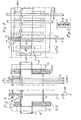
- FIG. 1 is an overall side view showing schematically and in principle, on a largly reduced scale, a jacquard machine which in-accordance with the invention is provided with manually adjustable acceleration/re- tardation spring tension means 3, 4, I, II, III, and IV for collective setting of acceleration and retardation springs 8, 9 which are placed in such a way relative to the sinkers 2 and the sinker guiding or selecting means 25, 26 respectively - according to my Swedish Patent Application No. 7808898-6 and the sinker operating means A and B according to my Swedish Patent No. 396 098 and Patent Application No. 7808771 - as to obtain satisfactory cooperation between these different elements and an adequate power transmission within the sinkers at full normal working speed and for the weaving machine/jacquard machine or for the fabric quality that can be produced in the weaving machine.
- Fig. 1 four spring tension means are designated by I, II, III and IV and out of these two and two, viz. respectively I, II and III, IV - are setting means for the spring tension means 3 and 4.
- I, II and III, IV setting means for the spring tension means 3 and 4.
- the means I is described in more detail here because the function of the spring tension and setting means I, II, III and IV is identical.
- the construction of the means I, II, III and IV is identical and for greater clarity the latter three have not been provided with any reference numerals in Fig. 1.
- the spring tension means 3 and 4 which in their simplest embodiment may consist of two relatively movable perforated plates reinforced by bars being vertically oriented thereto or - as will be described below - may be designed according to Figs. 3, 4, 5 and 6, are suspended in beams I4, II 4 , and IV 4 via screw connections and link systems I 5 , I 6 , I 7 mounted each on one side of a so-called sinker package.
- Each of the setting means I, II, III and VII is in turn suspended in an eccenter mechanism I 2 I3 and mounted each on one shaft I 1 , in pairs on either side of the sinker system.
- the spring tension means 3 and 4 carry, on their two opposite sides, rolls I 8 , II 8 , II 8 , IV 8 running vertically along supporting bars I 9 , II 9 , III 9' IV 9 whereby the means 3 and 4 are given checked vertical movements.
- the parallel beams I4, II 4' III 4 and IV 4 are fixed by means of screw connections I 5 and nuts I 10' I 11 . By loosening these and turning them in one or the other direction the screw connections and the spring tension means 3 and 4 connected therewith can be manually vertically moved to different heights.
- the shafts can in this connection move at most a half revolution between positions for minimum tension in the springs designated 8 and 9, corresponding to the distances S and S l .
- the step motors can obtain their control impulses from e.g. electrically active dynamic potentiometers, dynamometers or the like inertia sensing means attached e.g. to the sinker operating means A and B.
- the acceleration and retardation springs 8 and 9 accelerate and brake the sinkers in their opposite end positions because the springs and the spring tension means 3 and 4 are placed at the uppermost and lowermost positions of the sinker ends. Pull forces will always be exerted in the sinkers between their abutment beads or projections designated 6 and 7 which are captured by the sinker operating means A and B and the springs 8 and 9 which are kept in abutment with the spring tension means 3 and 4. This prevents bulging and consequently unnecessary vibration of the sinkers.
- the springs 8 and 9 are compressed between the spring tension means 3 and 4, respectively, and at abutment means 10 and 11 respectively attached to both ends of each sinker by means of a snap lock device 10, 11, 12, 13, 14 shown in Fig. 2.
- the snap lock device includes an abutment sleeve body 12 and a U-shaped means 12 at a longer shank provided with a hook-shaped end portion 12 1 .
- At the one end portion of the abutment sleeve body 11 is an eccentrically situated axial bore 11 1 and a shorter shank 12 2 is inserted therein to keep said U-shaped means in position.
- the longer shank provided with the hook-shaped end portion 12 1 extends along an axial slit towards and into a centrical bottom bore 11 2 at the opposite sleeve body end.
- a tangential recess 14 Arranged inwardly of the slit in the portion of the sleeve body 11 situated beyond the bottom of the last-mentioned bore 11 2 is a tangential recess 14.
- the bent-over end of the sinker 2 is intended to be inserted into the bore 11 3 where it is snap locked by the hook-shaped end 12 1 being snapped over it.
- the U-bent end portion 12 3 of the means 12 is adapted to serve as an attachment eye for a harness strap or for harness threads 15.
- Figs. 3 and 4 show, on an approximately natural scale, parts of an embodiment of the schematically illustrated spring tension means 3 and 4 in Fig. 1.
- Figs. 3 and 4 show only the uppermost spring tension means 3 but since the two spring tension means 3 and 4 can be of identical design numeral 4 corresponding to the bore or plate 4 in Fig. 1 has been put within parentheses.
- the spring tension means 3 and 4 in Fig. 1 symbolize the supporting bars 3a (4a), .3b (4b), 3c (4c) and 3d (4d) on which the spring tension means proper, designated 18, are borne.
- the spring tension means 18 include vertically positioned angle or L-bars of such a height that sufficient bending strength will be obtained.
- the angle bars are at their ends formed with lower portions 19 which rest in openings formed between the vertically and angularily adjustable support bars 3a (4a), 3b (4b), 3c (4c) and 3d (4d).
- the angle bars 18 rest substantially on the support bars 3a (4a) and 3d (4d) which, in turn, are suspended in the spring tension means I, II, III and IV as shown in Fig. 1.
- the lower outer ends of the angle or L-bars extend through parallel vertical slits 20 in bars 22, 23 fixedly mounted on the outside of the support bars in the machine and in this way they can maintain their equal interspaces and ver- ticality independently of vertical displacement.
- Another angle or L-shaped locking bar 17 bears against one portion, the narrower one, at the top of the angle bar 18.
- the lock bar is at even intervals perforated with oblong holes 16 which are shown in Figs. 3 and 5. These oblong holes correspond with similar holes in the spring tension bar 18.
- round holes are formed in which the sinkers 2 move up and down. If sinkers 2 are to be shifted the lock bar is displaced so that the oblong holes completely correspond which each other, whereby the sinkers 2 with its abutment beads or studs 6, 7 and guide hooks freely can be pulled therethrough.
- This is shown in a section through the angle bars 17 and 18 adjacent the sinker 2 seen to the left in Fig. 3.
- Figs. 3 and 4 show three sinkers localized in their lowermost turning positions in which the springs 8 are compressed.
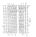
- Fig. 6 is a top view showing the support bars 4b and 4c and the sinkers 2, which are indicated by black dots, acceleration and retardation springs 8 and oblong holes 16 in lock bars 17 on the top of spring tension bars 18. Further the fixed bars 22, 23 with the parallel slits 21 indicated by broken lines can be seen.
- the figure also shows a cross-section through air impulse channels 27, of which only two are partly shown in Fig. 4. These channels extend across the uppermost spring tension means 3 in Fig. 1 with its spring tension bars 18 according to Fig. 4, said channel 27 being vertically mounted in rows in the openings between each spring tension bar 18 and lock bar 17. For greater clarity said pipes are not shown in Fig. 1 but so is the positioning of the guide bars 25 and 26.
Landscapes
- Engineering & Computer Science (AREA)
- Textile Engineering (AREA)
- Looms (AREA)
- Knitting Machines (AREA)
Applications Claiming Priority (2)
| Application Number | Priority Date | Filing Date | Title |
|---|---|---|---|
| SE8202527 | 1982-04-22 | ||
| SE8202527 | 1982-04-22 |
Publications (2)
| Publication Number | Publication Date |
|---|---|
| EP0093104A2 true EP0093104A2 (de) | 1983-11-02 |
| EP0093104A3 EP0093104A3 (de) | 1985-07-31 |
Family
ID=20346602
Family Applications (1)
| Application Number | Title | Priority Date | Filing Date |
|---|---|---|---|
| EP83850108A Withdrawn EP0093104A3 (de) | 1982-04-22 | 1983-04-22 | Vorrichtung für eine Jacquard-Maschine |
Country Status (2)
| Country | Link |
|---|---|
| EP (1) | EP0093104A3 (de) |
| WO (1) | WO1983003854A1 (de) |
Families Citing this family (1)
| Publication number | Priority date | Publication date | Assignee | Title |
|---|---|---|---|---|
| DE4131635C1 (de) * | 1991-09-23 | 1993-03-04 | Grosse Webereimaschinen Gmbh, 7910 Neu-Ulm, De |
Family Cites Families (2)
| Publication number | Priority date | Publication date | Assignee | Title |
|---|---|---|---|---|
| DE2227490A1 (de) * | 1971-06-09 | 1972-12-28 | Lauritsen, William Eger Nyboe, Lerum (Schweden) | Vorrichtung zur Erreichung der Steuerung der Bewegungen des Fadenführorgans bei einer Textilmaschine |
| SE396098B (sv) * | 1973-03-05 | 1977-09-05 | Lauritzen William Eger Nyboe | Anordning for mekanisk manovrering av trad- eller garnstyrningsorgan |
-
1983
- 1983-04-22 EP EP83850108A patent/EP0093104A3/de not_active Withdrawn
- 1983-04-22 WO PCT/SE1983/000160 patent/WO1983003854A1/en not_active Ceased
Also Published As
| Publication number | Publication date |
|---|---|
| WO1983003854A1 (en) | 1983-11-10 |
| EP0093104A3 (de) | 1985-07-31 |
Similar Documents
| Publication | Publication Date | Title |
|---|---|---|
| KR100840998B1 (ko) | 자카드형 직기의 쉐드 형성 장치 | |
| US4858654A (en) | Pulley-block drive open shed jacquard machine | |
| EP0379679A3 (de) | Schwingungsisolierte Webmaschine mit Niveauregelung | |
| EP0742297B1 (de) | Fadenspann- und Rückzugvorrichtung für eine Webmaschine | |
| CN104040055A (zh) | 带有用于形成附加纬面花纹的装置的织机 | |
| US4034782A (en) | Connecting member for securing pull elements to lifting wires of a jacquard machine | |
| EP1120485A3 (de) | Webmaschine zum Herstellen eines Drehergewebes | |
| EP0093104A2 (de) | Vorrichtung für eine Jacquard-Maschine | |
| US6957671B2 (en) | Device for creating a gauze fabric | |
| HK46396A (en) | Weft yarn presenting device for gripper looms | |
| US5462097A (en) | Piezoelectric devices for yarn control apparatus in a textile machine | |
| US6186186B1 (en) | Method and weaving machine for weaving a pile fabric | |
| EP0371257B1 (de) | Vorrichtung zum Bilden einer Dreherkante zum Einsatz auf einer Jacquard-Maschine | |
| JP3504673B2 (ja) | 織機綜絖と該綜絖を具備したジャカード織機 | |
| US4291730A (en) | Double-lift open-shed jacquard machine | |
| RU2184181C2 (ru) | Механизм регулирования зигзагообразного стежка | |
| EP1008679B1 (de) | Jacquardlitze | |
| EP3371356B1 (de) | Jacquardmaschine, doppel-teppichwebmaschine mit mindestens einer jacquardmaschine und verfahren zur einstellung einer jacquardmaschine | |
| JPS63120130A (ja) | 織物機械において製織密度を変更する装置 | |
| EP3987094B1 (de) | Fachbildungsvorrichtung | |
| EP0085108B1 (de) | Verfahren zum antrieb der schäfte einer schaftmaschine mit federrückzug, nockenmaschine mit federrückzug | |
| CA1108963A (en) | Harness for looms | |
| DE69406760T2 (de) | Riet mit eingebautem Deflektionswebschaft | |
| JPS6321588Y2 (de) | ||
| CN223118629U (zh) | 一种多装造控制系统剑杆织机 |
Legal Events
| Date | Code | Title | Description |
|---|---|---|---|
| PUAI | Public reference made under article 153(3) epc to a published international application that has entered the european phase |
Free format text: ORIGINAL CODE: 0009012 |
|
| AK | Designated contracting states |
Designated state(s): CH DE FR IT LI |
|
| PUAL | Search report despatched |
Free format text: ORIGINAL CODE: 0009013 |
|
| AK | Designated contracting states |
Designated state(s): CH DE FR IT LI |
|
| STAA | Information on the status of an ep patent application or granted ep patent |
Free format text: STATUS: THE APPLICATION IS DEEMED TO BE WITHDRAWN |
|
| 18D | Application deemed to be withdrawn |
Effective date: 19851031 |