EP0092390A2 - Container handling system - Google Patents
Container handling system Download PDFInfo
- Publication number
- EP0092390A2 EP0092390A2 EP83302122A EP83302122A EP0092390A2 EP 0092390 A2 EP0092390 A2 EP 0092390A2 EP 83302122 A EP83302122 A EP 83302122A EP 83302122 A EP83302122 A EP 83302122A EP 0092390 A2 EP0092390 A2 EP 0092390A2
- Authority
- EP
- European Patent Office
- Prior art keywords
- rail
- pallet
- storage
- receiving
- picking
- Prior art date
- Legal status (The legal status is an assumption and is not a legal conclusion. Google has not performed a legal analysis and makes no representation as to the accuracy of the status listed.)
- Withdrawn
Links
Images


Classifications
-
- B—PERFORMING OPERATIONS; TRANSPORTING
- B65—CONVEYING; PACKING; STORING; HANDLING THIN OR FILAMENTARY MATERIAL
- B65G—TRANSPORT OR STORAGE DEVICES, e.g. CONVEYORS FOR LOADING OR TIPPING, SHOP CONVEYOR SYSTEMS OR PNEUMATIC TUBE CONVEYORS
- B65G65/00—Loading or unloading
-
- B—PERFORMING OPERATIONS; TRANSPORTING
- B65—CONVEYING; PACKING; STORING; HANDLING THIN OR FILAMENTARY MATERIAL
- B65G—TRANSPORT OR STORAGE DEVICES, e.g. CONVEYORS FOR LOADING OR TIPPING, SHOP CONVEYOR SYSTEMS OR PNEUMATIC TUBE CONVEYORS
- B65G1/00—Storing articles, individually or in orderly arrangement, in warehouses or magazines
- B65G1/02—Storage devices
- B65G1/04—Storage devices mechanical
- B65G1/06—Storage devices mechanical with means for presenting articles for removal at predetermined position or level
- B65G1/08—Storage devices mechanical with means for presenting articles for removal at predetermined position or level the articles being fed by gravity
-
- B—PERFORMING OPERATIONS; TRANSPORTING
- B65—CONVEYING; PACKING; STORING; HANDLING THIN OR FILAMENTARY MATERIAL
- B65G—TRANSPORT OR STORAGE DEVICES, e.g. CONVEYORS FOR LOADING OR TIPPING, SHOP CONVEYOR SYSTEMS OR PNEUMATIC TUBE CONVEYORS
- B65G47/00—Article or material-handling devices associated with conveyors; Methods employing such devices
- B65G47/52—Devices for transferring articles or materials between conveyors i.e. discharging or feeding devices
Definitions
- the invention relates to a container handling system.
- Containers such as pallets
- the system of the invention is particularly suitable for handling palletized containers.
- Apparatus of the system is particularly useful in an order picking system in which the contents of loaded pallets are removed, and the empty pallets returned to a location where they can be picked up
- Prior art devices for this purpose are mechanically complex and therefore subject to high manufacturing costs as well as extensive maintenance procedures. Additionally, the prior art devices are subject to the possibility of operator error which can cause container handling accidents that are not only dangerous to the operator but are also not easily corrected.
- the invention aims to improve upon the prior art devices which are disclosed in U.S. Patent Nos. 4 068 751, 3 392 813 and French Patent No. 1 382 511.
- a container handling system for forwarding pallets in a longitudinal forwarding direction and returning the pallets in a longitudinal returning direction comprising; rails for gravity conveying the pallets between different pallet handling positions, the rails comprising a pallet storage rail, an order picking rail, and an empty pallet return rail, with the pallet storage rail having longitudinally opposed stored pallet receiving and loaded pallet forwarding ends;
- FIG. 1 the components of a container handling system are shown.
- the system comprises a storage rail 1, a picking or receiving rail 2, and a return rail 3.
- the rails 1 to 3 are of a kind which are normally used in gravity conveying of containers.
- aus rail may for example, comprise two side beams having interconnected between them axle rollers journalled to the beans at their ends; or, in another example, two side beams having cross beans connected between each other, the cross beams having roller wheels mounted for free rotational movement thereon.
- the rail could also comprise two side beams having a flat plate of metal extending between them so as to form a skid upon which the containers would slide.
- One kind of rail is not particularly favoured over another kind of rail so long as the containers can be conveyed from one end of the rail to the other end of the rail.
- the storage rail 1 as shown in Figure 1 may be associated with a container feeding conveyor 4 for feeding containers onto the storage rail 1.
- the containers may be pushed from the feed conveyor 4 by any conventional automatic pushing apparatus such as designated at 5.
- the storage rail 1 is movable between a container receiving and storage position, which is designated by the broken lines shown in Figure 1, and a container forwarding position which is indicated by the solid lines in Figure 1.
- the storage rail 1 In the container forwarding position, the storage rail 1 has a positive slope orientation.
- the storage rail 1 In the container receiving and storage position, the storage rail 1 has a negative slope orientation.
- the change in slope orientation of the storage rail 1 provides for controlling advance of containers on the storage rail 1.
- the slope orientation of the stroage rail in the container receiving and storage position could be generally level such that the force of gravity acts normal to the plane of the storage rail.
- the picking rail 2 has a container receiving end 6 for receiving a container being conveyed from the storage rail 1, and a container handling end 7.
- a container will begin to be conveyed in the longitudinal direction shown by the arrow F.
- the container receiving end 6 of the picking rail 2 will be in position adjacent to the storage rail for receiving the container being conveyed.
- the container will continue to be conveyed to the handling end 7. At this position the container may be removed from the picking rail 2 and deposited at another location, not shown.
- the system shown in Figure 1 is well suited for the handling of containers which are filled with contents to be emptied at the handling end 7 of the picking rail 2.
- the picking rail 2 can be pivoted between two positions, a container receiving position indicated by solid lines and a container returning position indicated by broken lines.
- the rail picking 2 In the container returning position the rail picking 2 is oriented such that the container receiving end 6 is adjacent the return rail 3.
- the container receiving end 6 is also a container returning end.
- the empty container, emptied at container handling end 7, then advances longitudinally in the direction of arrow R toward the return rail 3.
- the return rail 3 may be fixedly mounted at an incline equal to the slope of the picking rail 2 when the picking rail is in the empty container returning position.
- the return rail may be mounted at an inclination less than equal to the slope of the picking rail or the return rail may be mounted substantially level so long as a container being conveyed is received by the return rail 3 and conveyed to a temporary storage end 8 thereof. The container may then continue to advance beyond the end of the return rail to an empty container conveyor generally designated 9.
- FIG 2 shows in more detail the apparatus of the container handling system enclosed by the box A in Figure 1. This apparatus is particularly useful in the handling of palletized containers.
- the storage rail 1 shown in Figure 2 comprises two side members 53, only one of which can be seen in Figure 2.
- Roller wheels 54 extend across the surface of the rail 1.
- the wheels 54 are mounted on individual axles and allowed freely to rotate about the axles.
- the picking rail 2 and return rail 3 are similarly constructed, however many constructions allowing for the conveying of the containers across the surface of the rails are suitable as herein already described.
- the storage rail 1 is positioned for receiving a loaded pallet P.
- Loaded pallets may he placed on the storage rail 1 by a fork lift or by automatic conveying and pushing means 5 such as shown in Figure 1.
- the loaded pallet P abuts a pallet stop 11 at a receiving end 12 of the storage rail.
- a pallet stop would not be necessary at the receiving end 12 of the storage rail if the rail is positioned level or generally without enough positive slope or negative slope to affect movement of a pallet in either the forwarding direction indicated by the arrow F or in the opposite direction .
- No pallet stops are provided at a loaded pallet forwarding end 13 of the storage rail since forward conveying of the pallet is controlled by the changing of the slope orientation of the storage rail.
- the picking rail 2 has a container receiving end 6 which can receive pallets conveyed from the storage rail 1 to the picking rail 2.
- the receiving end 6 is also a returning end when the picking rail 2 is in the empty pallet return position as shown in Figure 4 and as discussed with respect to Figure 1.
- a pallet stop 14 is located at the container handling end 7 of the picking rail 2.
- the container handling end 7 is more specifically designated an order picking end. For example, when a pallet P is on the picking rail 2 and the end of the pallet is abutting the pallet stop 14 an operator may remove the contents from the pallet and place the contents at a location not shown.
- a pallet stop 14 would not be necessary however if the rail surface of picking rail 2 were a skid or some other frictional surface such that a container advancing in the direction of arrow F from the storage rail to the picking rail would stop at a location along the picking rail before it conveyed beyond the handling end 7.
- the return rail 3 shown in Figure 2 has an empty pallet receiving end 26 and is fixedly mounted at an inclination equal to the inclination of the picking rail 2 when the picking rail is in the empty pallet returning position.
- the return rail 3 is mounted at its end 8 by a return rail support 28 and at its end 26 by a loaded pallet forwarding end support 20 generally at 27.
- a pallet stop 15 is located at the temporary storage end 8 of the return rail 3.
- the pallet stop means 11, 14 and 15 may each comprise a plate of metal welded to the end of the rail at which the stop is located. Of course the stop may extend continuously the full width of the rail, extend part way the width of the rail, or extend only along one portion of the rail. The stops 11, 14 and 15 need to extend above the surface of the rail only to a height such that the pallet abuts the stop when hitting it and does not continue to advance over it.
- the storage rail 1 is mounted for pivotal movement about a horizontal axis located at the midway point between the receiving and loading ends by an axle 16 fixed to the storage rail and journalled to and supported by a pair of storage rail supports 17, only one of which can be seen in Figure 2, in conventional manner.
- the storage rail is moved between the receiving and forwarding positions by means of a storage rail operating lever 18, and a storage rail toggle linkage 19.
- the storage rail is locked in the receiving position when the lever 18 shown in Figure 5, is in the upright position as shown in Figure 2 and, the storage rail linkage 19 is over-centre and abutting a stop such as the pair of pallet forwarding end supports 20 only one of which is shown in Figure 2.
- the supports 20 support the storage rail 1 at the loaded pallet forwarding end 13 when the storage rail is in the loaded pallet forwarding position.
- the picking rail 2 when in the loaded pallet receiving position, is properly aligned with the storage rail 1 so that it may receive a pallet being conveyed. Movement of the picking rail 2 between the loaded pallet receiving position and the empty pallet returning position is achieved by a picking rail lever 21 shown in Figure 5 and a picking rail toggle linkage assembly 22.
- the picking rail is pivotally mounted at its order picking end 7 about a horizontal axis on an axle 23 fixed to the picking rail and journalled at it's opposite ends in a conventional manner to a pair of picking rail supports 24 only one of which can be seen in Figure 2.
- the picking rail is locked in the receiving position when the lever 21 is in the upright position as shown in Figure 2 and, the picking rail linkage assembly 22 is over-centre and abutting a stop 34.
- levers 18 and 21 are mounted for pivotal movement by a bolt 39 passing through lever bores 41, and supported by upstanding bolt supports 38.
- the levers are able to be rotated freely but are prevented from making substantial side to side movement by close tolerances between the diameter of the bolt 39 and the diameter of the lever bores 41.
- the levers 18 and 21 are mechanically restricted from being operated out of sequence such that pallet handling accidents due to operator error are reduced to a minimum.
- the levers 18 and 21 operate from the upright position and in both of two different embodiments are actuated by a single handle. Movement of the linkage 19 from its over-centre position is achieved by drawing back the lever 18 in the direction of arrow D shown in Figure 2. Similarly movement of the linkage 22 from its over-centre position by the lever 21 is achieved by drawing back the lever 21 in the direction of the arrow D. Restoring either of the levers 18 or 21 to their respective upright positions locks the respective linkages 19 and 22 in their respective upright positions. Additionally, the levers are restricted such that both cannot be operated, drawn back or returned to their upright positions, simultaneously when operated in the normal manner by use of the handle provided for operation of the levers.
- the sequence of steps followed in operating the apparatus of Figure 2 involves first receiving a pallet on the storage rail 1 when the lever 18 is in its upright position and therefore the storage rail is in the loaded pallet receiving position.
- the lever 18 is drawn back in the direction of arrow D to change the slope orientation of the storage rail to advance the pallet on the storage rail 1 longitudinally forward in the direction of arrow F.
- the picking rail operating lever 21 is prevented from moving the picking rail 2 after the storage rail operating lever 18 begins to operate the storage rail 1 in movement from the pallet receiving position to the pallet forwarding position.
- the picking rail, now locked in its upright position receives the pallet being conveyed from the storage rail 1.
- the pallet advances to the handling end 7 of the picking rail where it is stopped by the pallet stop 14 or by frictional engagement with the surface of the picking rail.
- the picking rail is pivoted to the empty pallet returning position such that the end 6 is lowered to be aligned with the rail 3, but not until the operating lever 18 is returned to its upright position and therefore the storage rail 1 returned to its position of negative or level slope orientation for receiving loaded pallets.
- the lever 21 is available to operate the picking rail toggle linkage 22 to lower the picking rail from the loaded pallet receiving position to the empty pallet returning position. Exact alignment of the picking rail 2 with the return rail 3 is provided by a picking rail alignment stop 25. The lever 18 is prevented from moving after the lever 21 is operated and begins to move the picking rail to the empty pallet returning position.
- each of the operating levers can only be operated from a position where both are in the upright position, a loaded pallet cannot be forwarded from the storage rail 1 to the picking rail 2 when the picking rail is in the empty pallet returning position.
- a "Do Not Load" sign 35 is visable from the storage rail loading end of the apparatus as can be seen in Figure 8.
- the sign 35 is hidden from view in the pallet storage position by a storage rail cross beam 36 which is at the end 12 of the storage rail as can be seen in Figure 2. Further, the sign 35 is mounted to storage rail supporting posts 37 which support the storage rail when the storage rail is in the pallet storage and receiving position.
- the storage rail is shown in the pallet forwarding position, with the storage rail resting on the storage forwarding end support 20.
- the linkage assembly 22 is shown in the over-centre position abutting the stop 34.
- the storage rail In the position shown in Figure 3 the storage rail is in position for forwarding a loaded pallet to the picking rail which is in position for receiving a loaded pallet.
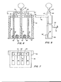
- FIG. 2 and 5 One embodiment for restricting the movement of the storage rail and picking rail operating levers is shown in Figures 2 and 5.
- the levers are operated by handle 29 which can be received in one of two operating lever bores 30 and 31 located in the levers 18 and 21 respectively.
- the handle 29 When the levers 18 and 21 are in the upright position the handle 29 may be inserted within either of the bores 30 and 31.
- Mounted on each of the levers 18 and 21 are a storage rail bore shroud 32 and a picking rail bore shroud 33, as can be seen in Figure 5.
- the placement of the shroud is such that when the lever 21 is drawn back in the direction of arrow D the picking rail shroud 33 covers the bore 30, preventing the insertion of the handle 29 and therefore preventing the operation of the lever 18 in the normal manner as described.
- the shroud 32 covers the bore 31 preventing insertion of the handle 29 into the bore 31 and therefore preventing the drawing back of the elever 21 in the normal manner as described.
- FIG. 6 Another embodiment for restricting movement of the storage rail and picking rail operating levers is shown in Figures 6, 7 and 9.
- the levers are operated by a handle 29' which is anchored by a bolt 39' through a lever bore 40 as can be seen in Figure 6.
- Operating levers 18' and 21' operate the storage rail linkage 19 and the picking rail linkage 22 respectively.
- the levers 18' and 21' are mounted for pivotal movement at the base of each lever by a bolt 39' passing through respective lever mounting bores 41.
- the bolt 39' passes through bores 42 in upstanding bolt supports 38'. A close tolerance between the diameter of the bolt 39 and the bores 40, 41' and 42' is not necessary as herein will be described.
- the diameter of the bore 40 be greater than the diameter of the bolt 39' so that the handle 29' will be able to move from side to side such that on the one side it engages with a cut-out portion 43 of the lever 18' and on the other side it engages with a cut-out portion 44 of the lever 21'.
- a guide plate 46 restricts the movement of the handle 29' to move only within two guideways 45 and 47.
- the guideway 45 allows the lever 18' to be pulled backward while maintaining engagement of the handle 29' within the cut-out 43.
- the guideway 47 allows the lever 21' to be pulled back while maintaining engagement of the handle 29' within the cut-out 44.
- Further guideways 48 and 49 are provided for supporting the levers 18' and 21' against side to side movement.
- Vertical guide plate supports 50 provide for supporting the guide plate 46 just vertically beneath handle engaging portions 51 and 52 of the storage and picking rail operating levers 18' and 21' respectively.
- a portion 53 of the guide plate 46 which extends between the guideways 45 and 47 prevents the handle 29' from being pulled backward while in possible engagement with both of the cut-out portions 43 and 44.
- the levers 18' and 21' are of substantially the same height such that there is no overlapping of the engagement portions 51 and 52 when the levers 18' and 21' are urged toward each other.
- each of the lever operating assembly embodiments the components are dimensioned to allow free travel of the levers in the directions necessary to actuate the movement of the storage and picking rails as has been herein described.
Landscapes
- Engineering & Computer Science (AREA)
- Mechanical Engineering (AREA)
- Warehouses Or Storage Devices (AREA)
- Rollers For Roller Conveyors For Transfer (AREA)
- Intermediate Stations On Conveyors (AREA)
Abstract
In a container handling system palletised containers (P) are conveyed along a storage rail (1 after tilting the rail (1) anticlockwise from the position shown, onto and along a picking rail (2). After unloading, the empty pallets are conveyed back along the picking rail (2), by tilting the rail (2) clockwise from the position shown, onto a pallet return rail (3). The tilting controls of the rails (1 and 2) are interlocked to prevent the rail (1) being tilted from the position shown if the rail (2) is not in the position shown.
Description
- The invention relates to a container handling system.
- Containers, such as pallets, are frequently required to be conveyed from one location to another in material handling operations. The system of the invention is particularly suitable for handling palletized containers. Apparatus of the system is particularly useful in an order picking system in which the contents of loaded pallets are removed, and the empty pallets returned to a location where they can be picked up
- Prior art devices for this purpose are mechanically complex and therefore subject to high manufacturing costs as well as extensive maintenance procedures. Additionally, the prior art devices are subject to the possibility of operator error which can cause container handling accidents that are not only dangerous to the operator but are also not easily corrected. The invention aims to improve upon the prior art devices which are disclosed in U.S. Patent Nos. 4 068 751, 3 392 813 and French Patent No. 1 382 511.
- It is an object of the present invention to improve upon the prior art devices by providing an apparatus within a container handling system which is of a simple mechanical construction. and which is prevented from being operated in a manner that can cause container handling accidents and possible bodily harm to the operator.
- It is also an object of the invention to provide apparatus within a container handling system for the forwarding of loaded containers and the returning of empty containers which an operator can control from one location.
- According to the invention there is provided a container handling system for forwarding pallets in a longitudinal forwarding direction and returning the pallets in a longitudinal returning direction comprising; rails for gravity conveying the pallets between different pallet handling positions, the rails comprising a pallet storage rail, an order picking rail, and an empty pallet return rail, with the pallet storage rail having longitudinally opposed stored pallet receiving and loaded pallet forwarding ends;
- wherein the pallet storage rail is mounted for movement between a loaded pallet forwarding position having a positive slope orientation corresponding with said longitudinal forwarding direction; and, a stored pallet receiving position having a negative slope orientation relative to said positive slope orientation;
- a first pallet stop means is provided at said stored pallet receiving end of the pallet storage rail for preventing a pallet from moving off said pallet storage rail when the pallet storage rail is in said negative slope orientation; the order picking rail has longitudinally opposed ends, one of said ends being an order picking end and the other of said ends being a loaded pallet receiving and empty pallet returning end;
- the order picking rail is mounted for movement such that said receiving and returning end can move between a loaded pallet receiving position and an empty pallet returning position;
- operating means are provided to move the pallet storage rail between said storage pallet receiving position and said loaded pallet forwarding position to produce a change in said slope orientation for moving a loaded pallet in said longitudinal forwarding direction from said stored pallet receiving position to said loaded pallet forwarding position;
- the order picking rail is oriented relative to the storage rail such that when a loaded pallet is received at the loaded pallet receiving end the pallet continues to advance in said longitudinal forwarding direction to said order picking end;
- second pallet stop means are provided at said order picking end for preventing a pallet from advancing off said order picking rail in said longitudinal forwarding direction;
- the empty pallet return rail has longitudinally opposed empty pallet receiving and temporary storing ends;
- the empty pallet return rail has a third pallet stop means at said storing end for stopping a pallet from advancing therebeyond in said longitudinal returning direction;
- picking rail operating means are provided to move the order picking rail between said loaded pallet receiving position and said empty pallet returning position such that when a loaded pallet is on the storage rail and the storage rail is in said loaded pallet forwarding position, the loaded pallet will firstly be received by said pallet receiving and empty pallet returning end, secondly
- be advanced in said longitudinal forwarding direction to said order picking end where the pallet is to be emptied, then thirdly as an empty pallet, be advanced in said longitudinal returning direction to said loaded pallet receiving and empty pallet returning end and fourthly be advanced further to be received by said empty pallet return rail; and
- the empty pallet return rail is oriented relative to the order picking rail such that when an empty pallet is received from the order picking rail at said empty pallet receiving end the empty pallet advances in said longitudinal returning direction to said empty pallet storing end.
- The invention is diagrammatically illustrated by way of example in the accompanying drawings, in which:-
- Figure 1 is an overall diagram of a container handling system according to the invention;
- Figure 2 is a more detailed side elevation of the apparatus enclosed within box A of Figure 1;
- Figure 3 is a fragmentary side elevation of the apparatus shown in Figure 2 in the loaded pallet forwarding position;
- Figure 4 is a fragmentary side elevation of the apparatus shown in Figure 2 in the empty pallet returning position;
- Figure 5 is a front elevation of one embodiment of storage and picking rail operating levers of a system according to the invention;
- Figure 6 is a front sectional view of another embodiment of storage and picking rail operating levers of a system according to the invention;
- Figure 7 is a top plan view partly in section of the embodiment shown in Figure 6 taken substantially upon a plane passing along section line 7-7;
- Figure 8 is a partial end elevation of the apparatus shown in Figure 2;
- Figure 9 is side elevation of the operating levers embodied in Figure 6.
- In Figure 1 the components of a container handling system are shown. The system comprises a storage rail 1, a picking or receiving
rail 2, and areturn rail 3. The rails 1 to 3 are of a kind which are normally used in gravity conveying of containers. Fach rail, may for example, comprise two side beams having interconnected between them axle rollers journalled to the beans at their ends; or, in another example, two side beams having cross beans connected between each other, the cross beams having roller wheels mounted for free rotational movement thereon. The rail could also comprise two side beams having a flat plate of metal extending between them so as to form a skid upon which the containers would slide. One kind of rail is not particularly favoured over another kind of rail so long as the containers can be conveyed from one end of the rail to the other end of the rail. - The storage rail 1 as shown in Figure 1 may be associated with a container feeding conveyor 4 for feeding containers onto the storage rail 1. The containers may be pushed from the feed conveyor 4 by any conventional automatic pushing apparatus such as designated at 5.
- The storage rail 1 is movable between a container receiving and storage position, which is designated by the broken lines shown in Figure 1, and a container forwarding position which is indicated by the solid lines in Figure 1. In the container forwarding position, the storage rail 1 has a positive slope orientation. In the container receiving and storage position, the storage rail 1 has a negative slope orientation. The change in slope orientation of the storage rail 1 provides for controlling advance of containers on the storage rail 1. The slope orientation of the stroage rail in the container receiving and storage position could be generally level such that the force of gravity acts normal to the plane of the storage rail. In the case where a container is on the storage rail and the storage rail is level, the movement of a container in a longitudinal forwarding direction as indicated by the arrow F in Figures 1 and 2 would still be controlled by changing the slope orientation of the storage rail to the positive slope orientation corresponding with the storage rail being in the container forwarding direction.
- The picking
rail 2 has a container receiving end 6 for receiving a container being conveyed from the storage rail 1, and acontainer handling end 7. When the slope orientation of the storage rail 1 is changed from the negative slope orientation of the receiving position to the positive slope orientation of the container forwarding position, a container will begin to be conveyed in the longitudinal direction shown by the arrow F. The container receiving end 6 of the pickingrail 2 will be in position adjacent to the storage rail for receiving the container being conveyed. The container will continue to be conveyed to thehandling end 7. At this position the container may be removed from the pickingrail 2 and deposited at another location, not shown. - The system shown in Figure 1 is well suited for the handling of containers which are filled with contents to be emptied at the
handling end 7 of thepicking rail 2. For handling such containers, the pickingrail 2 can be pivoted between two positions, a container receiving position indicated by solid lines and a container returning position indicated by broken lines. In the container returning position therail picking 2 is oriented such that the container receiving end 6 is adjacent thereturn rail 3. In this embodiment the container receiving end 6 is also a container returning end. The empty container, emptied atcontainer handling end 7, then advances longitudinally in the direction of arrow R toward thereturn rail 3. - The
return rail 3 may be fixedly mounted at an incline equal to the slope of the pickingrail 2 when the picking rail is in the empty container returning position. Alternatively the return rail may be mounted at an inclination less than equal to the slope of the picking rail or the return rail may be mounted substantially level so long as a container being conveyed is received by thereturn rail 3 and conveyed to atemporary storage end 8 thereof. The container may then continue to advance beyond the end of the return rail to an empty container conveyor generally designated 9. - Figure 2 shows in more detail the apparatus of the container handling system enclosed by the box A in Figure 1. This apparatus is particularly useful in the handling of palletized containers.
- The storage rail 1 shown in Figure 2 comprises two
side members 53, only one of which can be seen in Figure 2.Roller wheels 54 extend across the surface of the rail 1. Thewheels 54 are mounted on individual axles and allowed freely to rotate about the axles. The pickingrail 2 andreturn rail 3 are similarly constructed, however many constructions allowing for the conveying of the containers across the surface of the rails are suitable as herein already described. - In Figure 2 the storage rail 1 is positioned for receiving a loaded pallet P. Loaded pallets may he placed on the storage rail 1 by a fork lift or by automatic conveying and
pushing means 5 such as shown in Figure 1. The loaded pallet P abuts a pallet stop 11 at a receivingend 12 of the storage rail. A pallet stop would not be necessary at the receivingend 12 of the storage rail if the rail is positioned level or generally without enough positive slope or negative slope to affect movement of a pallet in either the forwarding direction indicated by the arrow F or in the opposite direction .once the pallet is loaded onto the storage rail. No pallet stops are provided at a loadedpallet forwarding end 13 of the storage rail since forward conveying of the pallet is controlled by the changing of the slope orientation of the storage rail. - As earlier stated in the description of Figure 1 the picking
rail 2 has a container receiving end 6 which can receive pallets conveyed from the storage rail 1 to the pickingrail 2. The receiving end 6 is also a returning end when the pickingrail 2 is in the empty pallet return position as shown in Figure 4 and as discussed with respect to Figure 1. Apallet stop 14 is located at thecontainer handling end 7 of the pickingrail 2. In the handling of palletized contents thecontainer handling end 7 is more specifically designated an order picking end. For example, when a pallet P is on the pickingrail 2 and the end of the pallet is abutting the pallet stop 14 an operator may remove the contents from the pallet and place the contents at a location not shown. Apallet stop 14 would not be necessary however if the rail surface of pickingrail 2 were a skid or some other frictional surface such that a container advancing in the direction of arrow F from the storage rail to the picking rail would stop at a location along the picking rail before it conveyed beyond the handlingend 7. - The
return rail 3 shown in Figure 2 has an empty pallet receiving end 26 and is fixedly mounted at an inclination equal to the inclination of the pickingrail 2 when the picking rail is in the empty pallet returning position. Thereturn rail 3 is mounted at itsend 8 by areturn rail support 28 and at its end 26 by a loaded pallet forwardingend support 20 generally at 27. Apallet stop 15 is located at thetemporary storage end 8 of thereturn rail 3. - The pallet stop means 11, 14 and 15 may each comprise a plate of metal welded to the end of the rail at which the stop is located. Of course the stop may extend continuously the full width of the rail, extend part way the width of the rail, or extend only along one portion of the rail. The stops 11, 14 and 15 need to extend above the surface of the rail only to a height such that the pallet abuts the stop when hitting it and does not continue to advance over it.
- When a pallet is first loaded onto the storage rail 1 of Figure 3 positioned in the container receving position, it is prevented from being forwarded to the picking
rail 2 by means of the negative slope orientation or level orientation of the storage rail as discussed in the description of Figure 1. The storage rail 1 is mounted for pivotal movement about a horizontal axis located at the midway point between the receiving and loading ends by anaxle 16 fixed to the storage rail and journalled to and supported by a pair of storage rail supports 17, only one of which can be seen in Figure 2, in conventional manner. The storage rail is moved between the receiving and forwarding positions by means of a storagerail operating lever 18, and a storagerail toggle linkage 19. The storage rail is locked in the receiving position when thelever 18 shown in Figure 5, is in the upright position as shown in Figure 2 and, thestorage rail linkage 19 is over-centre and abutting a stop such as the pair of pallet forwarding end supports 20 only one of which is shown in Figure 2. The supports 20 support the storage rail 1 at the loadedpallet forwarding end 13 when the storage rail is in the loaded pallet forwarding position. - The picking
rail 2, when in the loaded pallet receiving position, is properly aligned with the storage rail 1 so that it may receive a pallet being conveyed. Movement of the pickingrail 2 between the loaded pallet receiving position and the empty pallet returning position is achieved by a pickingrail lever 21 shown in Figure 5 and a picking railtoggle linkage assembly 22. The picking rail is pivotally mounted at itsorder picking end 7 about a horizontal axis on anaxle 23 fixed to the picking rail and journalled at it's opposite ends in a conventional manner to a pair of picking rail supports 24 only one of which can be seen in Figure 2. The picking rail is locked in the receiving position when thelever 21 is in the upright position as shown in Figure 2 and, the pickingrail linkage assembly 22 is over-centre and abutting astop 34. - With reference to Figure 5, the
levers bolt 39 passing through lever bores 41, and supported by upstanding bolt supports 38. The levers are able to be rotated freely but are prevented from making substantial side to side movement by close tolerances between the diameter of thebolt 39 and the diameter of the lever bores 41. - The
levers levers linkage 19 from its over-centre position is achieved by drawing back thelever 18 in the direction of arrow D shown in Figure 2. Similarly movement of thelinkage 22 from its over-centre position by thelever 21 is achieved by drawing back thelever 21 in the direction of the arrow D. Restoring either of thelevers respective linkages - The sequence of steps followed in operating the apparatus of Figure 2 involves first receiving a pallet on the storage rail 1 when the
lever 18 is in its upright position and therefore the storage rail is in the loaded pallet receiving position. Thelever 18 is drawn back in the direction of arrow D to change the slope orientation of the storage rail to advance the pallet on the storage rail 1 longitudinally forward in the direction of arrow F. the pickingrail operating lever 21 is prevented from moving the pickingrail 2 after the storagerail operating lever 18 begins to operate the storage rail 1 in movement from the pallet receiving position to the pallet forwarding position. The picking rail, now locked in its upright position receives the pallet being conveyed from the storage rail 1. The pallet advances to the handlingend 7 of the picking rail where it is stopped by the pallet stop 14 or by frictional engagement with the surface of the picking rail. At this point the contents of the pallet are removed to another location not shown. When the empty pallet is desired to be returned to thereturn rail 3, the picking rail is pivoted to the empty pallet returning position such that the end 6 is lowered to be aligned with therail 3, but not until the operatinglever 18 is returned to its upright position and therefore the storage rail 1 returned to its position of negative or level slope orientation for receiving loaded pallets. Once thestorage rail lever 18 has been returned to its upright position, thelever 21 is available to operate the pickingrail toggle linkage 22 to lower the picking rail from the loaded pallet receiving position to the empty pallet returning position. Exact alignment of the pickingrail 2 with thereturn rail 3 is provided by a pickingrail alignment stop 25. Thelever 18 is prevented from moving after thelever 21 is operated and begins to move the picking rail to the empty pallet returning position. - Because each of the operating levers can only be operated from a position where both are in the upright position, a loaded pallet cannot be forwarded from the storage rail 1 to the picking
rail 2 when the picking rail is in the empty pallet returning position. - When the apparatus of Figure 2 is used in an order picking system and pallets are placed on the storage rail 1 from a fork lift truck, the operator of the fork lift is instructed not to load a pallet onto the storage rail when the storage rail is in the pallet forwarding position. To aid the operator in determining the position of the storage rail, a "Do Not Load"
sign 35 is visable from the storage rail loading end of the apparatus as can be seen in Figure 8. Thesign 35 is hidden from view in the pallet storage position by a storagerail cross beam 36 which is at theend 12 of the storage rail as can be seen in Figure 2. Further, thesign 35 is mounted to storagerail supporting posts 37 which support the storage rail when the storage rail is in the pallet storage and receiving position. Should a fork lift operator place a loaded pallet on the storage rail 1 when it is in its pallet forwarding position the pallet would simply move forward onto the picking rail where it would stop by frictional engagement with the surface of the picking rail or by means of thepallet stop 14. As stated, the picking rail would necessarily be in the loaded pallet receiving position. If a pallet were, however already on the picking rail the loaded pallet placed on the storage rail in error would advance until it abutted with the pallet already on the picking rail. This type of accident, although not prevented by the restricted movement of the levers may be easily corrected by returning the storage rail to its loaded pallet receiving position thereby changing the slope orientation of the storage rail in error to advance in the direction opposite to the arrow F until it abuts the pallet stop 11. - In Figure 3 the storage rail is shown in the pallet forwarding position, with the storage rail resting on the storage forwarding
end support 20. Thelinkage assembly 22 is shown in the over-centre position abutting thestop 34. In the position shown in Figure 3 the storage rail is in position for forwarding a loaded pallet to the picking rail which is in position for receiving a loaded pallet. i - In Figure 4 the picking rail is shown in the empty pallet returning position. The end 6 of the
rail 2 is shown resting on thealignment stop 25. Thelinkage 19 is in the over-centre position the abutting storage rail forwardingend support 20, while thelinkage 22 is in the position achieved whenlever 21 is drawn back in the direction of arrow D. I - One embodiment for restricting the movement of the storage rail and picking rail operating levers is shown in Figures 2 and 5. In this embodiment, the levers are operated by
handle 29 which can be received in one of two operating lever bores 30 and 31 located in thelevers levers handle 29 may be inserted within either of thebores 30 and 31. Mounted on each of thelevers shroud 32 and a picking rail boreshroud 33, as can be seen in Figure 5. The placement of the shroud is such that when thelever 21 is drawn back in the direction of arrow D the pickingrail shroud 33 covers thebore 30, preventing the insertion of thehandle 29 and therefore preventing the operation of thelever 18 in the normal manner as described. Similarly when thelever 18 is drawn backward in the direction of arrow D, theshroud 32 covers the bore 31 preventing insertion of thehandle 29 into the bore 31 and therefore preventing the drawing back of theelever 21 in the normal manner as described. - Another embodiment for restricting movement of the storage rail and picking rail operating levers is shown in Figures 6, 7 and 9. In this embodiment the levers are operated by a handle 29' which is anchored by a bolt 39' through a lever bore 40 as can be seen in Figure 6. Operating levers 18' and 21' operate the
storage rail linkage 19 and the pickingrail linkage 22 respectively. The levers 18' and 21' are mounted for pivotal movement at the base of each lever by a bolt 39' passing through respective lever mounting bores 41. The bolt 39' passes throughbores 42 in upstanding bolt supports 38'. A close tolerance between the diameter of thebolt 39 and thebores 40, 41' and 42' is not necessary as herein will be described. Actually it is preferred that the diameter of thebore 40 be greater than the diameter of the bolt 39' so that the handle 29' will be able to move from side to side such that on the one side it engages with a cut-outportion 43 of the lever 18' and on the other side it engages with a cut-outportion 44 of the lever 21'. Aguide plate 46 restricts the movement of the handle 29' to move only within twoguideways guideway 45 allows the lever 18' to be pulled backward while maintaining engagement of the handle 29' within the cut-out 43. Similarly, theguideway 47 allows the lever 21' to be pulled back while maintaining engagement of the handle 29' within the cut-out 44.Further guideways guide plate 46 just vertically beneathhandle engaging portions portion 53 of theguide plate 46 which extends between theguideways portions engagement portions - In each of the lever operating assembly embodiments the components are dimensioned to allow free travel of the levers in the directions necessary to actuate the movement of the storage and picking rails as has been herein described.
Claims (9)
1. A container handling system for forwarding pallets in a longitudinal forwarding direction and returning the pallets in a longitudinal returning direction comprising:
rails for gravity conveying the pallets between different pallet handling positions, the rails comprising a pallet storage rail, an order picking rail, and an empty pallet return rail, with the pallet storage rail having longitudinally opposed stored pallet receiving and loaded pallet forwarding ends; characterised in that the pallet storage rail (1) is mounted for movement between a loaded pallet forwarding position having a positive slope orientation corresponding with said longitudinal forwarding direction (F); and, a stored pallet receiving position having a negative slope orientation relative to said positive slope orientation;
a first pallet stop means (11) is provided at said stored pallet receiving end (12) of the pallet storage rail for preventing a pallet (P) from moving off said pallet storage rail (1) when the pallet storage rail (1) is in said negative slope orientation;
the order picking rail (2) has longitudinally opposed ends, one (6) of said ends being an order picking end and the other (6) of said ends being a loaded pallet receiving and empty pallet returning end;
the order picking rail (2) is mounted for movement such that said receiving and returning end (6) can move between a loaded pallet receiving position and an empty pallet returning position;
operating means (18, 19) are provided to move the pallet storage rail (1) between said storage pallet receiving position and said loaded pallet forwarding position to produce a change in said slope orientation for moving a loaded pallet (P) in said longitudinal forwarding direction (F) from said stored pallet receiving position to said loaded pallet forwarding position; the order picking rail (2) is oriented relative to the storage rail (1) such that when a loaded pallet (P) is received at the loaded pallet receiving end (6) the pallet (P) continues to advance in said longitudinal forwarding direction (F) to said order picking end (7);
second pallet stop means (14) are provided at said order picking end (7) for preventing a pallet (P) from advancing off said order picking rail (2) in said longitudinal forwarding direction (F);
the empty pallet return rail (3) has longitudinally opposed empty pallet receiving (26) and temporary storing (8) ends;
the empty pallet return rail (3) has a third pallet stop means (15) at said storing end (8) for stopping a pallet from advancing therebeyond in said longitudinal returning direction (R);
picking rail operating means (21, 22) are provided to move the order picking rail (2) between said loaded pallet receiving position and said empty pallet returning position such that when a loaded pallet is on the storage rail (1) and the storage rail (1) is in said loaded pallet forwarding position, the loaded pallet will firstly be received by said pallet receiving and empty pallet returning end (12), secondly be advanced in said longitudinal forwarding direction (F) to said order picking end (7) where the pallet is to be emptied, then thirdly as an empty pallet, be advanced in said longitudinal returning direction (R) to said loaded pallet receiving and empty pallet returning end (6) and fourthly be advanced further to be received by said empty pallet return rail (3); and
the empty pallet return rail (3) is oriented relative to the order picking rail (2) such that when an empty pallet is received from the order picking rail (2) at said empty pallet receiving end (26) the empty pallet advances in said longitudinal returning direction (R) to said empty pallet storing end (8).
2. A container handling system according to claim 1, characterised in that the picking rail operating means (21, 22) and the storage rail operating means (18, 19) further comprise;
restricting means (30 to 33, 43 to 47) for preventing the picking rail operating means (21, 22) from moving the picking rail (2) after the storage rail operating means (18, 19) begins to move the storage rail (1) from said stored pallet receiving position to said loaded pallet forwarding position such that a loaded pallet is prevented from advancing in said longitudinal forwarding direction (F) from the storage rail (1) to the order picking rail (2) when the order picking rail (2) is in said empty pallet returning position; and, for preventing said storage rail operating means (18, 19) from moving the storage rail (1) after the order picking rail operating means (21, 22) begins to move the order picking rail (2) to said empty pallet returning position such that a loaded pallet on the storage rail (1) when the storage rail (1) is in said stored pallet receiving position cannot advance when the order picking rial (2) is not in said loaded pallet receiving position.
3. A container handling system according to claim 2, characterised in that the picking rail operating means (21, 22) and the storage rail operating means (18, 19) further, comprise:
a storage rail operaitng lever (18) mounted for pivotal movement;
a picking rail operating lever (21) mounted for pivotal movement;
a storage rail linkage (19) connecting the storage rail lever (18) to the pallet storage rail (1) for transferring pivotal movement of the storage rail lever (18) to the storage rail (1) for effecting pivotal movement of the storage rail (1); and
a picking rail linkage (22) connecting the picking rail lever (21) to the order picking rail (2) for transferring pivotal movement of the picking rail lever (21) to the picking rail (2) for effecting pivotal movement of the picking rail (2).
4. A container handling system according to claim 3, characterised by: a single operating handle (29);
a bore (31) in the picking rail lever (21) for receiving the handle (29);
a bore (30) in the storage rail lever (18) for receiving the handle (29);
the restricting means comprising a picking rail shroud (33) which covers the bore (30) in the storage rail lever (18) when the picking rail lever (21) is actuating the picking rail linkage (22) and a storage rail shroud (32) which covers the bore (31) in the picking rail lever (21) when the storage rail lever (18) is actuating the storage rail linkage (19).
5. A container handling system according to claim 3, characterised in that the picking rail operating means (21, 22) and the storage rail operating means (18, 19) further comprise:
a single handle (29') for use with said picking (21') and said storage (18') rail operating levers;
a handle mounting means (39' 40) for allowing the handle (29') to be moved between the storage rail operating lever (18') and the picking rail operating lever (21') such that the handle (29') is available to singly interconnect with eiether the storage rail operating lever (18') or the picking rail operating lever (21') but not both of the levers (18', 19') simultaneously.
6. A container handling system according to claim 1, characterised in that the rails (1, 2, 3) further comprise: ' roller wheels (54) mounted for free rotational movement about an axis planar with the rails (1, 2, 3) such that the storage rail (1) has a roller surface for receiving and conveying a pallet (P) to the pallet forwarding end (13);
the picking rail (2) has a roller surface (54) for receiving and conveying a pallet (P) to the order picking end (7) and thereafter conveying a pallet to the empty pallet returning end (6); and,
the return rail (3) has a roller surface (54) for receiving and conveying a pallet to the empty pallet storing end (8).
7. Container handling apparatus for longitudinally forwarding containers in a longitudinal forward direction comprising:
a storage rail having means for the gravity conveying of a container associated on the surface of said rail and
a container receiving rail having longitudinally opposed container receiving and container handling ends;
characterised in that the storage rail (1) is movable between a container forwarding position having a positive container forwarding slope corresponding with said longitudinal forwarding direction (F) and a container receiving and storage position having a negative slope relative to said positive slope;
operating means (18, 19) are provided for moving the storage rail (1) between said forwarding and said receiving positions and are operable from said container handling end (7);
the storage rail (1) is disposed at a higher level than the container receiving end (6) of the container receiving rail (2) such that when a container is placed on the storage rail when the storage rail (1) is in said forwarding position the container will advance in said longitudinal forwarding direction
(F) to the container receiving rail (2); and
the container receiving rail (2) is oriented relative to the storage rail (1) such that when a container is received from the storage rail (1) at the container receiving end (6) the container will continue to advance in said longitudinal forwarding direction to the container handling end (7).
8. Container handling apparatus according to claim 6, characterised in that the container receiving rail (2) further includes: ' means for aligning the receiving end (6) with the storage rail (1) while further having a slope equal to said positive slope of the storage rail (1); and,
a container stop means (14) for stopping a container from advancing in said longitudinal forwarding direction at said container handling end (7) of the receiving rail (2).
9. A container handling system for forwarding pallets in a longitudinal direction and returning pallets in a longitudinal direction comprising:
rails for the gravity conveying of pallets between different pallet handling positions characterised in that;
the rails comprise a pallet storage rail (1), an order picking rail (2), and an empty pallet return rail (3);
the pallet storage rail (1) has longitudinally opposed loaded pallet receiving (12) and loaded pallet forwarding (13) ends;
the pallet storage rail (1) is mounted for movement between a loaded pallet forwarding position having a positive slope orientation corresponding with said longitudinal forwarding direction (F); and, a stored pallet receiving position having a level slope orientation relative to said positive slope orientation;
the order picking rail (2) has longitudinally opposed ends, one of said ends being an order picking end (7) and, the other of said ends being a loaded pallet receiving and empty pallet returning end (6);
the order picking rail (2) is mounted for movement such that the receiving and returning end (6) can move between a loaded pallet receiving position and an empty pallet returning position;
storage rail operating means are provided to move the pallet storage rail (1) between said storage pallet receiving position and said loaded pallet forwarding position to produce a change in said slope orientation for moving a loaded pallet in said longitudinal forwarding direction (F) from said stored pallet receiving position to said loaded pallet forwarding position;
the order picking rail (2) is oriented relative to the storage rail (1) such that when a loaded pallet (P) is received at said loaded pallet receiving end (6) the pallet (P) continues to advance in said longitudinal forwarding direction (F) to said order picking end (7);
first pallet stop means (14) are provided at said order picking end (7) for preventing a pallet (P) from advancing off the order picking rail (2) in said longitudinal forwarding direction (F);
the empty pallet return rail (3) has longitudinally opposed empty pallet receiving (26) and temporary storing (8) ends;
the empty pallet return rail (3) has a second pallet stop means (15) at the storing end (8) for stopping a pallet from advancing in said longitudinal returning direction;
picking rail operating means (21, 22) are provided operable to move the order picking rail (2) between said loaded pallet receiving position and said empty pallet returning position such that when a loaded pallet is on the storage rail (1) and the storage rail (1) is in said loaded pallet forwarding position the loaded pallet (P) will first be received by said pallet receiving and empty pallet returning end (6) second by advanced in said longitudinal forwarding direction (F) to said order picking end (7) where the pallet is to be emptied, then third, as an empty pallet, be advanced in said longitudinal returning direction (R) to the loaded pallet receiving and empty pallet returning end (6) and fourth be advanced further to be received by the empty pallet return rail (3); and
the empty pallet return rail (3) is oriented relative to the order picking rail (2) such that when an empty pallet is received from said order picking rail (2) at said empty pallet receiving end (26) the empty pallet advances in said longitudinal returning direction (R) to said empty pallet storing end (8).
Applications Claiming Priority (2)
| Application Number | Priority Date | Filing Date | Title |
|---|---|---|---|
| US368843 | 1982-04-15 | ||
| US06/368,843 US4485910A (en) | 1982-04-15 | 1982-04-15 | Container handling system |
Publications (2)
| Publication Number | Publication Date |
|---|---|
| EP0092390A2 true EP0092390A2 (en) | 1983-10-26 |
| EP0092390A3 EP0092390A3 (en) | 1984-09-12 |
Family
ID=23452988
Family Applications (1)
| Application Number | Title | Priority Date | Filing Date |
|---|---|---|---|
| EP83302122A Withdrawn EP0092390A3 (en) | 1982-04-15 | 1983-04-14 | Container handling system |
Country Status (7)
| Country | Link |
|---|---|
| US (1) | US4485910A (en) |
| EP (1) | EP0092390A3 (en) |
| JP (1) | JPS58193827A (en) |
| AU (1) | AU1327583A (en) |
| BR (1) | BR8301897A (en) |
| CA (1) | CA1195350A (en) |
| ZA (1) | ZA832316B (en) |
Cited By (5)
| Publication number | Priority date | Publication date | Assignee | Title |
|---|---|---|---|---|
| DE3341710A1 (en) * | 1983-11-18 | 1985-05-30 | Walter Dr.-Ing. 5100 Aachen Jürgens | Rack |
| FR2616134A1 (en) * | 1987-06-05 | 1988-12-09 | Interroll Foerdertechnik Gmbh | Device for flow storage and handling of articles |
| WO1992012082A1 (en) * | 1990-12-27 | 1992-07-23 | E.B. Eddy Forest Products Ltd. | Bin manipulation system |
| FR2699897A1 (en) * | 1992-12-24 | 1994-07-01 | Sipa Roller | Storage and unloading unit for articles in boxes, pallets or packages |
| WO2014006014A1 (en) * | 2012-07-03 | 2014-01-09 | Kuka Systems Gmbh | Feed apparatus and method |
Families Citing this family (22)
| Publication number | Priority date | Publication date | Assignee | Title |
|---|---|---|---|---|
| US4621745A (en) * | 1984-10-24 | 1986-11-11 | Grace Robert W | Mechanized carton picker |
| US4701092A (en) * | 1985-02-15 | 1987-10-20 | Yarbrough'o Machine Shop | Pallet dispenser |
| US5236104A (en) * | 1992-05-01 | 1993-08-17 | Frederick J. Stingel, Jr. | Multiple pressure container storage and retrieval apparatus |
| US5111963A (en) * | 1991-05-24 | 1992-05-12 | Frederick J. Stingel | Container storage and dispensing apparatus |
| US5567103A (en) * | 1994-10-21 | 1996-10-22 | Konstant; Anthony N. | Unloading device |
| US5617961A (en) * | 1995-06-07 | 1997-04-08 | Konstant Products, Inc. | Load transfer and return system |
| US5779094A (en) * | 1996-01-22 | 1998-07-14 | Stingel, Jr.; Frederick J. | Article reception system for storage and dispensing apparatus |
| US6186725B1 (en) * | 1999-05-25 | 2001-02-13 | Konstant Products, Inc. | Container pick and return system |
| DE19953812A1 (en) * | 1999-11-09 | 2001-05-23 | Psb Gmbh Materialflus & Logist | Method and device for picking |
| US6557724B1 (en) * | 2000-08-30 | 2003-05-06 | Jervis B. Webb Company | Vertical conveyor |
| US6468015B1 (en) | 2001-04-25 | 2002-10-22 | Konstant Products, Inc. | Container pick and return system |
| US6588608B2 (en) * | 2001-06-01 | 2003-07-08 | Konstant Products, Inc. | Storage system with automatic elevator |
| FR2885123B1 (en) * | 2005-04-27 | 2009-01-23 | Stalder Sa Ets | DEVICE FOR LOADING AND UNLOADING PALLETS |
| JP4978052B2 (en) * | 2005-11-09 | 2012-07-18 | 日産自動車株式会社 | Work conveying apparatus and work conveying method |
| US7553118B1 (en) * | 2008-05-08 | 2009-06-30 | The Schnipke Family LLC | Diverter and method for moving bodies between levels of an assembly line or other structure |
| US8616370B2 (en) | 2010-10-28 | 2013-12-31 | Arrows Up, Inc. | Bulk material shipping container |
| US8887914B2 (en) | 2010-10-28 | 2014-11-18 | Arrows Up, Inc. | Bulk material shipping container |
| DE102016109310A1 (en) * | 2016-05-20 | 2017-11-23 | Deutsche Post Ag | Slide and sorting device and method for sorting piece goods |
| CA2945454C (en) | 2016-06-30 | 2023-11-07 | Arrows Up, Llc | Bulk material shipping container |
| US11661235B2 (en) | 2018-10-15 | 2023-05-30 | Sandbox Enterprises, Llc | Bulk material shipping container top wall assembly and bulk material shipping container having a top wall assembly |
| US10926940B2 (en) | 2018-11-20 | 2021-02-23 | Sandbox Enterprises, Llc | Bulk material shipping container |
| CN117125491B (en) * | 2023-10-27 | 2024-01-02 | 江苏奥汇能源科技有限公司 | Solar cell turnover storage device |
Citations (7)
| Publication number | Priority date | Publication date | Assignee | Title |
|---|---|---|---|---|
| US3157296A (en) * | 1959-11-24 | 1964-11-17 | Ass Elect Ind | Control systems for load-conveying installations |
| FR1382511A (en) * | 1964-02-10 | 1964-12-18 | Retractable roller station for pallets | |
| GB994456A (en) * | 1960-06-13 | 1965-06-10 | British Boot Shoe & Allied Tra | Storage device |
| US3392813A (en) * | 1966-11-16 | 1968-07-16 | Country Entpr | Container handling apparatus |
| US3517430A (en) * | 1967-05-05 | 1970-06-30 | Molins Machine Co Ltd | Work-setting stations |
| DE2001443A1 (en) * | 1969-01-16 | 1970-07-30 | North American Rockwell | Single lever control device for hydrostatic transmissions |
| US4068751A (en) * | 1976-01-29 | 1978-01-17 | The Kingston-Warren Corporation | Gravity feed-return pallet storage rack |
Family Cites Families (4)
| Publication number | Priority date | Publication date | Assignee | Title |
|---|---|---|---|---|
| US3057448A (en) * | 1959-04-02 | 1962-10-09 | Andrew T Kornylak | Gravity type conveyor |
| US3093229A (en) * | 1961-01-23 | 1963-06-11 | Horace D Hume | Box handling apparatus |
| JPS5238852Y2 (en) * | 1972-11-16 | 1977-09-03 | ||
| SU521191A1 (en) * | 1973-03-26 | 1976-07-15 | Проектно-Конструкторское Технологическое Бюро Министерства Мясной И Молочной Промышленности Украинской Сср | Gravity rack |
-
1982
- 1982-04-15 US US06/368,843 patent/US4485910A/en not_active Expired - Lifetime
-
1983
- 1983-03-23 CA CA000424305A patent/CA1195350A/en not_active Expired
- 1983-03-30 ZA ZA832316A patent/ZA832316B/en unknown
- 1983-04-08 AU AU13275/83A patent/AU1327583A/en not_active Abandoned
- 1983-04-13 BR BR8301897A patent/BR8301897A/en unknown
- 1983-04-14 EP EP83302122A patent/EP0092390A3/en not_active Withdrawn
- 1983-04-15 JP JP58065752A patent/JPS58193827A/en active Pending
Patent Citations (7)
| Publication number | Priority date | Publication date | Assignee | Title |
|---|---|---|---|---|
| US3157296A (en) * | 1959-11-24 | 1964-11-17 | Ass Elect Ind | Control systems for load-conveying installations |
| GB994456A (en) * | 1960-06-13 | 1965-06-10 | British Boot Shoe & Allied Tra | Storage device |
| FR1382511A (en) * | 1964-02-10 | 1964-12-18 | Retractable roller station for pallets | |
| US3392813A (en) * | 1966-11-16 | 1968-07-16 | Country Entpr | Container handling apparatus |
| US3517430A (en) * | 1967-05-05 | 1970-06-30 | Molins Machine Co Ltd | Work-setting stations |
| DE2001443A1 (en) * | 1969-01-16 | 1970-07-30 | North American Rockwell | Single lever control device for hydrostatic transmissions |
| US4068751A (en) * | 1976-01-29 | 1978-01-17 | The Kingston-Warren Corporation | Gravity feed-return pallet storage rack |
Cited By (10)
| Publication number | Priority date | Publication date | Assignee | Title |
|---|---|---|---|---|
| DE3341710A1 (en) * | 1983-11-18 | 1985-05-30 | Walter Dr.-Ing. 5100 Aachen Jürgens | Rack |
| FR2616134A1 (en) * | 1987-06-05 | 1988-12-09 | Interroll Foerdertechnik Gmbh | Device for flow storage and handling of articles |
| WO1992012082A1 (en) * | 1990-12-27 | 1992-07-23 | E.B. Eddy Forest Products Ltd. | Bin manipulation system |
| FR2699897A1 (en) * | 1992-12-24 | 1994-07-01 | Sipa Roller | Storage and unloading unit for articles in boxes, pallets or packages |
| WO2014006014A1 (en) * | 2012-07-03 | 2014-01-09 | Kuka Systems Gmbh | Feed apparatus and method |
| CN104470832A (en) * | 2012-07-03 | 2015-03-25 | 库卡系统有限责任公司 | Feed apparatus and method |
| US9446905B2 (en) | 2012-07-03 | 2016-09-20 | Kuka Systems Gmbh | Feed device and method |
| EP3170772A1 (en) | 2012-07-03 | 2017-05-24 | KUKA Systems GmbH | Supply device |
| CN107651431A (en) * | 2012-07-03 | 2018-02-02 | 库卡系统有限责任公司 | Conveying device and method |
| CN107651431B (en) * | 2012-07-03 | 2019-09-20 | 库卡系统有限责任公司 | Conveying device and method |
Also Published As
| Publication number | Publication date |
|---|---|
| ZA832316B (en) | 1983-12-28 |
| CA1195350A (en) | 1985-10-15 |
| US4485910A (en) | 1984-12-04 |
| JPS58193827A (en) | 1983-11-11 |
| BR8301897A (en) | 1983-12-20 |
| EP0092390A3 (en) | 1984-09-12 |
| AU1327583A (en) | 1983-10-20 |
Similar Documents
| Publication | Publication Date | Title |
|---|---|---|
| EP0092390A2 (en) | Container handling system | |
| EP0184293B1 (en) | Vertically accumulating storage and dispensing apparatus | |
| US3642158A (en) | Turnaround device for a pallet conveyor | |
| EP1211198B1 (en) | Pallet handling method and apparatus | |
| EP0323478A1 (en) | Transfer vehicle to eliminate the accumulation of errors occurring in the placing of packages in a consecutive store. | |
| KR870700058A (en) | Cargo feeder for push flow racks | |
| US6719126B2 (en) | Device for transferring mail bins | |
| US6089819A (en) | Method and apparatus for palletizing and depalletizing layers of articles on stackable pallets | |
| US4950119A (en) | Storage and retrieval system | |
| US3994407A (en) | Can palletizer | |
| CN112811200A (en) | Automatic stacking system for cartons | |
| US3228542A (en) | Apparatus for the conveyance of standard size objects | |
| US5391046A (en) | Automated apparatus for loading and unloading motor vehicles | |
| EP0550919B1 (en) | Apparatus for loading containers with stacks of egg-filled trays and unloading same | |
| JP2003505315A (en) | Equipment for storing and transporting large containers | |
| JPH06219511A (en) | Automatic warehouse for picking | |
| US6394744B1 (en) | Stacking machine for part trays | |
| JPH0224736B2 (en) | ||
| US20040131451A1 (en) | Load pick-up device and method for the storage of articles in an order-picking system | |
| CN218087222U (en) | Tallying device and tallying system | |
| JP2985621B2 (en) | In / out transfer device | |
| JPH0780570B2 (en) | Picking device | |
| JPH0780571B2 (en) | Picking device | |
| JPH0784254B2 (en) | Picking device | |
| JPH03186517A (en) | Heaping device for angle steel member |
Legal Events
| Date | Code | Title | Description |
|---|---|---|---|
| PUAI | Public reference made under article 153(3) epc to a published international application that has entered the european phase |
Free format text: ORIGINAL CODE: 0009012 |
|
| AK | Designated contracting states |
Designated state(s): CH DE FR GB IT LI |
|
| PUAL | Search report despatched |
Free format text: ORIGINAL CODE: 0009013 |
|
| AK | Designated contracting states |
Designated state(s): CH DE FR GB IT LI |
|
| STAA | Information on the status of an ep patent application or granted ep patent |
Free format text: STATUS: THE APPLICATION IS DEEMED TO BE WITHDRAWN |
|
| 18D | Application deemed to be withdrawn |
Effective date: 19850514 |
|
| RIN1 | Information on inventor provided before grant (corrected) |
Inventor name: TABLER, CHARLES P. |