EP0092015A1 - Ionisierungsvorrichtung - Google Patents
Ionisierungsvorrichtung Download PDFInfo
- Publication number
- EP0092015A1 EP0092015A1 EP82810160A EP82810160A EP0092015A1 EP 0092015 A1 EP0092015 A1 EP 0092015A1 EP 82810160 A EP82810160 A EP 82810160A EP 82810160 A EP82810160 A EP 82810160A EP 0092015 A1 EP0092015 A1 EP 0092015A1
- Authority
- EP
- European Patent Office
- Prior art keywords
- electrodes
- current
- transistor
- generator
- pair
- Prior art date
- Legal status (The legal status is an assumption and is not a legal conclusion. Google has not performed a legal analysis and makes no representation as to the accuracy of the status listed.)
- Withdrawn
Links
- 230000011664 signaling Effects 0.000 claims abstract description 8
- 206010043268 Tension Diseases 0.000 claims 1
- 230000002159 abnormal effect Effects 0.000 description 3
- 238000011282 treatment Methods 0.000 description 3
- 238000013459 approach Methods 0.000 description 2
- 238000006243 chemical reaction Methods 0.000 description 2
- 238000010586 diagram Methods 0.000 description 2
- 238000005868 electrolysis reaction Methods 0.000 description 2
- 229920006395 saturated elastomer Polymers 0.000 description 2
- 230000001960 triggered effect Effects 0.000 description 2
- 230000006978 adaptation Effects 0.000 description 1
- 230000015572 biosynthetic process Effects 0.000 description 1
- 239000004020 conductor Substances 0.000 description 1
- 230000000694 effects Effects 0.000 description 1
- 229920001971 elastomer Polymers 0.000 description 1
- 239000004744 fabric Substances 0.000 description 1
- 238000000752 ionisation method Methods 0.000 description 1
- 230000035515 penetration Effects 0.000 description 1
- 239000000523 sample Substances 0.000 description 1
Images
Classifications
-
- A—HUMAN NECESSITIES
- A61—MEDICAL OR VETERINARY SCIENCE; HYGIENE
- A61N—ELECTROTHERAPY; MAGNETOTHERAPY; RADIATION THERAPY; ULTRASOUND THERAPY
- A61N1/00—Electrotherapy; Circuits therefor
- A61N1/18—Applying electric currents by contact electrodes
- A61N1/20—Applying electric currents by contact electrodes continuous direct currents
- A61N1/30—Apparatus for iontophoresis, i.e. transfer of media in ionic state by an electromotoric force into the body, or cataphoresis
Definitions
- the present invention relates to an ionization device comprising at least one adjustable current generator and at least one pair of electrodes detachably connected to said generator by connection means.
- This ionization consists in passing a direct current of low intensity between two parts of the patient's body, which causes electrolysis facilitating the penetration of the treatment solution.
- the devices used for this purpose comprise several pairs of plug-in electrodes each connected to an adjustable current generator. These generators are isolated from each other and generally include a milliammeter allowing the current in the corresponding probe to be measured.
- the object of the present invention is to remedy the disadvantages mentioned above, that is to say to produce an ionization device practically and automatically eliminating any risk of burns due to handling errors.
- the device further comprises means connected to said generator for determining the intensity of the current delivered by said generator to said electrodes, said means depending on the type of pair of electrodes connected to said generator.
- the current of the latter can be determined automatically so as to eliminate any risk of burns to the patient.
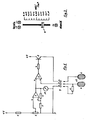
- the current generator of fig. 1 is formed by an adjustable voltage divider formed by a resistor 1 connected to the positive pole of the power supply and a potentiometer 2 connected to the negative pole of the power supply (ground).
- the potentiometer cursor is connected to the direct input (+) of an operational amplifier 3, the output of which is connected by a resistor 4 to its inverting input (-), itself connected to ground by a resistor 5.
- This well-known configuration makes it possible to obtain at the output of the amplifier a voltage proportional to the voltage EU on its direct input according to the relationship
- the voltage Us is applied to the direct input of a second operational amplifier 6, the output of which is connected by a resistor 7 to the base of a transistor 8 connected to a common collector, this transistor acting as a power amplifier.
- the emitter of transistor 8 is connected to terminal 9a of a three-pole connector 9, terminal 9b of which is connected to the inverting input of amplifier 6, and terminal 9c of which is connected to ground.
- the connector 9 makes it possible to connect the generator to a pair of electrodes 10a and 10b.
- the electrodes of a pair are generally of the same surface, but they can be of different surfaces depending on the parts of the patient's body to which they are applied.
- the smaller surface electrode is then decisive for the density of the current delivered between the electrodes.
- They generally include a wire mesh mounted on rubber and covered with a cloth or sponge.
- Each electrode is connected by a flexible conductor to a terminal of a suitable plug.
- this plug includes at least a third terminal c to which an adjustment element is connected, in this case a resistor 11 connected moreover to the electrode 10a.
- This resistor can be mounted directly in the plug or ecore on the electrode 10a, but in all cases it must remain integral with the pair of electrodes, the electrode-resistance assembly forming a whole.
- the voltage at the input which reverses from the amplifier 6 is maintained at the same value as the voltage on its direct input, this provided that a sufficient current can pass between the electrodes 10a and 10b. This is the case when the electrodes have been correctly placed on the patient.
- the value of the current Ie in the electrodes is then determined by the voltage between the input which inverts se of the amplifier 6 and the mass, according to the relation:
- the value of the current therefore depends on the one hand on the position ⁇ of the potentiometer cursor, which is obvious, but also on the resistance R11.
- the current per unit area that is to say the current density
- the current per unit area becomes independent of the type of the pair of electrodes used and that it does not depends more than on the position ⁇ of the potentiometer.
- R11 1 kiloohm, which allows a maximum current of 2.5 mA always corresponding to a current density of 0.1 m A / cm 2 .
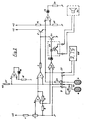
- this instrument is replaced by a light emitting diode (LED) 14 whose light intensity varies in proportion to the current density.
- LED light emitting diode
- the input which reverses from the amplifier 6 is connected to the direct input of an operational amplifier 13 with a counter circuit. reaction formed by an LED 14 and a resistor 15.
- the current in the diode 14 is equal to Us / R15, that is to say to ⁇ ⁇ Usmax / R15, intensity proportional to the position of the cursor of the potentiometer 2, at least under normal operating conditions.
- One of the first anomalies that can occur is too high resistance to the flow of current through the electrodes. This excessively high resistance may be due to the fact that the electrodes are incorrectly positioned and that they are partially detached, which produces a reduction in the effective current flow area and a local overcurrent. It is therefore necessary to limit the voltage across the electrodes. This voltage Ue is proportional to the resistance Re between electrodes:
- the emitter of transistor 8 is connected to the direct input of a voltage comparator 18, the inverting input of which is connected to a voltage divider formed by resistors 16 and 17 delivering on this input which inverts a reference voltage slightly lower than the supply voltage.
- a safety circuit comprising a voltage comparator 21 whose inverting input is connected to the inverting input of the amplifier 6 and by the terminal 9b of the connector 9 to the resistor 11, l 'direct input of this comparator 21 being connected to the input which inverts the amplifier 3.
- the voltage on this input is determined by the voltage divider formed by resistors R4 and R5 according to the relation: When the voltage across R11 falls below this value, the output of comparator 21 changes to + V. A current then flows through a light-emitting diode 22 (LED) signaling "safety”, then through an optocoupler 23 in the base of a transistor 24 whose emitter is grounded and whose collector is connected to the base of transistor 8.
- LED light-emitting diode 22
- This transistor 24 therefore becomes conductive and it short-circuits the base of transistor 8 against ground.
- the transistor 8 becomes non-conductive and it no longer passes any current through the electrodes.
- the power supply is interrupted.
- the outputs of the optocoupler 23 can also be connected to the inputs of a siren 30 which delivers an acoustic signal in order to warn the operator if the latter is not close to the device when security is triggered.
- a low value resistor 26 is connected in series in the electrode supply circuit. This resistor 26 is connected to the two terminals of a connector 27, a connector to which a digital or analog measuring instrument 28 can be connected.
- Ionization devices always include several pairs of electrodes and several current generators, it is thus possible to successively check the current in each pair of electrodes by means of a single measuring instrument by plugging it into the connectors provided for this purpose.
- Figure 3 shows an example of possible arrangement of the elements 2, 14, 19 and 22, allowing rapid control of the proper functioning of the device.
- a linear potentiometer associated with a graduation in mA / cm 2 allows precise dosing of the current for all types of electrode pairs used.
Landscapes
- Health & Medical Sciences (AREA)
- Engineering & Computer Science (AREA)
- Biomedical Technology (AREA)
- Nuclear Medicine, Radiotherapy & Molecular Imaging (AREA)
- Radiology & Medical Imaging (AREA)
- Life Sciences & Earth Sciences (AREA)
- Animal Behavior & Ethology (AREA)
- General Health & Medical Sciences (AREA)
- Public Health (AREA)
- Veterinary Medicine (AREA)
- Electrotherapy Devices (AREA)
- Measurement Of Current Or Voltage (AREA)
Priority Applications (2)
| Application Number | Priority Date | Filing Date | Title |
|---|---|---|---|
| EP82810160A EP0092015A1 (de) | 1982-04-16 | 1982-04-16 | Ionisierungsvorrichtung |
| JP58065786A JPS5946976A (ja) | 1982-04-16 | 1983-04-15 | イオン化装置 |
Applications Claiming Priority (1)
| Application Number | Priority Date | Filing Date | Title |
|---|---|---|---|
| EP82810160A EP0092015A1 (de) | 1982-04-16 | 1982-04-16 | Ionisierungsvorrichtung |
Publications (1)
| Publication Number | Publication Date |
|---|---|
| EP0092015A1 true EP0092015A1 (de) | 1983-10-26 |
Family
ID=8190056
Family Applications (1)
| Application Number | Title | Priority Date | Filing Date |
|---|---|---|---|
| EP82810160A Withdrawn EP0092015A1 (de) | 1982-04-16 | 1982-04-16 | Ionisierungsvorrichtung |
Country Status (2)
| Country | Link |
|---|---|
| EP (1) | EP0092015A1 (de) |
| JP (1) | JPS5946976A (de) |
Cited By (14)
| Publication number | Priority date | Publication date | Assignee | Title |
|---|---|---|---|---|
| EP0278474A1 (de) * | 1987-02-10 | 1988-08-17 | Drug Delivery Systems Inc. | Elektrolytische Zuführung von Polypeptiden durch die Haut |
| EP0278473A1 (de) * | 1987-02-10 | 1988-08-17 | Drug Delivery Systems Inc. | Transdermale, elektrolytische Zuführung von Proteinen |
| WO1988008729A1 (en) * | 1987-05-15 | 1988-11-17 | Newman Martin H | Iontophoresis drug delivery system |
| US4931046A (en) * | 1987-05-15 | 1990-06-05 | Newman Martin H | Iontophoresis drug delivery system |
| WO1993010854A1 (en) * | 1991-12-03 | 1993-06-10 | Alza Corporation | Iontophoretic delivery device and power supply therefor |
| WO1993011830A1 (en) * | 1991-12-11 | 1993-06-24 | Alza Corporation | Indicator for iontophoresis system |
| WO1995025562A1 (en) * | 1992-06-02 | 1995-09-28 | Alza Corporation | Electrotransport drug delivery device |
| WO1998044985A1 (en) * | 1997-04-04 | 1998-10-15 | Becton Dickinson And Company | Disabling circuit for an iontophoretic system |
| WO1998044984A1 (en) * | 1997-04-04 | 1998-10-15 | Becton Dickinson And Company | Automatic switch off iontophoretic system |
| EP0904801A3 (de) * | 1997-08-27 | 2000-01-05 | Becton, Dickinson and Company | Verfahren zum Feststellen von Ereignissen und Zuständen in einer iontophoretischen Verabreichungs-Vorrichtung |
| US6035234A (en) * | 1995-06-02 | 2000-03-07 | Alza Corporation | Electrotransport delivery device with voltage boosting circuit |
| US6090095A (en) * | 1994-12-08 | 2000-07-18 | Alza Corporation | Electrotransport delivery device |
| FR2793695A1 (fr) * | 1999-05-20 | 2000-11-24 | Becton Dickinson Co | Circuits pour augmenter la fiabilite d'un systeme d'ionophorese |
| US6175763B1 (en) | 1996-03-29 | 2001-01-16 | Alza Corporation | Electrotransport drug delivery device having tactile signaling means |
Families Citing this family (3)
| Publication number | Priority date | Publication date | Assignee | Title |
|---|---|---|---|---|
| US4622031A (en) * | 1983-08-18 | 1986-11-11 | Drug Delivery Systems Inc. | Indicator for electrophoretic transcutaneous drug delivery device |
| US4865582A (en) * | 1987-06-05 | 1989-09-12 | Drug Delivery Systems Inc. | Disposable transdermal drug applicators |
| EP0315027A3 (de) * | 1987-11-04 | 1990-10-31 | General Electric Company | Amidester-Blockcopolymere und Verfahren zu deren Herstellung |
Citations (5)
| Publication number | Priority date | Publication date | Assignee | Title |
|---|---|---|---|---|
| CH385366A (de) * | 1958-05-27 | 1964-12-15 | Rose Ewald | Elektrisches Gerät zur kosmetischen Behandlung der Haut |
| FR2153191A1 (de) * | 1971-09-24 | 1973-05-04 | Cressia Ste Civile Etu Rech | |
| FR2180666A1 (de) * | 1972-04-17 | 1973-11-30 | Sybron Corp | |
| US4141359A (en) * | 1976-08-16 | 1979-02-27 | University Of Utah | Epidermal iontophoresis device |
| GB2064178A (en) * | 1979-11-26 | 1981-06-10 | Sybron Corp | Electrical supply for ion therapy |
-
1982
- 1982-04-16 EP EP82810160A patent/EP0092015A1/de not_active Withdrawn
-
1983
- 1983-04-15 JP JP58065786A patent/JPS5946976A/ja active Pending
Patent Citations (5)
| Publication number | Priority date | Publication date | Assignee | Title |
|---|---|---|---|---|
| CH385366A (de) * | 1958-05-27 | 1964-12-15 | Rose Ewald | Elektrisches Gerät zur kosmetischen Behandlung der Haut |
| FR2153191A1 (de) * | 1971-09-24 | 1973-05-04 | Cressia Ste Civile Etu Rech | |
| FR2180666A1 (de) * | 1972-04-17 | 1973-11-30 | Sybron Corp | |
| US4141359A (en) * | 1976-08-16 | 1979-02-27 | University Of Utah | Epidermal iontophoresis device |
| GB2064178A (en) * | 1979-11-26 | 1981-06-10 | Sybron Corp | Electrical supply for ion therapy |
Cited By (21)
| Publication number | Priority date | Publication date | Assignee | Title |
|---|---|---|---|---|
| EP0278474A1 (de) * | 1987-02-10 | 1988-08-17 | Drug Delivery Systems Inc. | Elektrolytische Zuführung von Polypeptiden durch die Haut |
| EP0278473A1 (de) * | 1987-02-10 | 1988-08-17 | Drug Delivery Systems Inc. | Transdermale, elektrolytische Zuführung von Proteinen |
| WO1988008729A1 (en) * | 1987-05-15 | 1988-11-17 | Newman Martin H | Iontophoresis drug delivery system |
| US4931046A (en) * | 1987-05-15 | 1990-06-05 | Newman Martin H | Iontophoresis drug delivery system |
| WO1993010854A1 (en) * | 1991-12-03 | 1993-06-10 | Alza Corporation | Iontophoretic delivery device and power supply therefor |
| AU659269B2 (en) * | 1991-12-11 | 1995-05-11 | Alza Corporation | Indicator for iontophoresis system |
| WO1993011830A1 (en) * | 1991-12-11 | 1993-06-24 | Alza Corporation | Indicator for iontophoresis system |
| WO1995025562A1 (en) * | 1992-06-02 | 1995-09-28 | Alza Corporation | Electrotransport drug delivery device |
| US5466217A (en) * | 1992-06-02 | 1995-11-14 | Alza Corporation | Iontophoretic drug delivery apparatus |
| US6090095A (en) * | 1994-12-08 | 2000-07-18 | Alza Corporation | Electrotransport delivery device |
| US7708731B2 (en) | 1995-06-02 | 2010-05-04 | Alza Corporation | Electrotransport delivery device with voltage boosting circuit |
| US6842640B2 (en) | 1995-06-02 | 2005-01-11 | Alza Corporation | Electrotransport delivery device with voltage boosting circuit |
| US6035234A (en) * | 1995-06-02 | 2000-03-07 | Alza Corporation | Electrotransport delivery device with voltage boosting circuit |
| US6175763B1 (en) | 1996-03-29 | 2001-01-16 | Alza Corporation | Electrotransport drug delivery device having tactile signaling means |
| WO1998044984A1 (en) * | 1997-04-04 | 1998-10-15 | Becton Dickinson And Company | Automatic switch off iontophoretic system |
| WO1998044985A1 (en) * | 1997-04-04 | 1998-10-15 | Becton Dickinson And Company | Disabling circuit for an iontophoretic system |
| EP0904801A3 (de) * | 1997-08-27 | 2000-01-05 | Becton, Dickinson and Company | Verfahren zum Feststellen von Ereignissen und Zuständen in einer iontophoretischen Verabreichungs-Vorrichtung |
| FR2793695A1 (fr) * | 1999-05-20 | 2000-11-24 | Becton Dickinson Co | Circuits pour augmenter la fiabilite d'un systeme d'ionophorese |
| FR2799656A1 (fr) * | 1999-05-20 | 2001-04-20 | Becton Dickinson Co | Circuits pour augmenter la fiabilite d'un systeme d'ionophorese |
| FR2799655A1 (fr) * | 1999-05-20 | 2001-04-20 | Becton Dickinson Co | Circuits pour augmenter la fiabilite d'un systeme d'ionophorese |
| US6678555B2 (en) | 1999-05-20 | 2004-01-13 | Vyteris, Inc. | Circuits for increasing the reliability of an iontophoretic system |
Also Published As
| Publication number | Publication date |
|---|---|
| JPS5946976A (ja) | 1984-03-16 |
Similar Documents
| Publication | Publication Date | Title |
|---|---|---|
| EP0092015A1 (de) | Ionisierungsvorrichtung | |
| EP0261118B1 (de) | Energieversorgung für reifenüberwachungsanlage | |
| US4229733A (en) | Exposure detecting device | |
| FR2524756A1 (de) | ||
| FR2493077A1 (fr) | Circuit de commande d'un stimulateur therapeutique pour traitement de l'incontinence urinaire | |
| FR2481807A1 (fr) | Dispositif de commutation pour la surveillance d'un compteur statique d'electricite | |
| FR2551217A1 (fr) | Dispositif pour detecter la circulation d'un courant dans un ou plusieurs conducteurs | |
| US2232959A (en) | Electric rate meter | |
| EP0544589B1 (de) | Gerät zur Messung des realen Lastfaktors eines elektrischen Generators | |
| FR2741158A1 (fr) | Circuit testeur de compteur | |
| EP0489665A1 (de) | Anordnung zur Isolationskontrolle mit erhöhter Genauigkeit | |
| FR2517150A1 (fr) | Circuit telephonique gere par microprocesseur a circuit integre de transmission 2 fils-4 fils et alimentation de sauvegarde par courant de ligne | |
| EP0454542B1 (de) | Kontrollvorrichtung, die zur Messung der Wirksamkeit eines elektrischen Zaunes dient | |
| EP0549464A1 (de) | Gerät und Verfahren zur Messung des Ladezustandes eines elektrochemischen Generators | |
| FR2564648A1 (fr) | Disjoncteur a declencheur electronique et a calibres multiples | |
| EP0635725B1 (de) | Elektronische Schaltung zur Kontrolle der Anwesenheit von Spannungen in elektrischen Leitungen und zum Vergleichen deren Phasenlage | |
| CH406451A (fr) | Dispositif électrométrique | |
| FR2660070A1 (fr) | Controleur de presence de tension electrique a tenir a la main, a sensibilite equivalente que l'on utilise ou non un cordon de mise a la terre. | |
| FR2530353A1 (fr) | Dispositif a eclairs adapte pour etre rendu actif en reponse a la luminance de l'objet a photographier | |
| FR2586552A1 (fr) | Generateur d'impulsions de courant electrique, destine notamment aux mesures d'excitabilite neuro-musculaire | |
| FR2904525A1 (fr) | Dispositif d'evaluation de donnees physiologiques provenant de detecteurs | |
| CA2160720C (fr) | Detecteur de mauvais contacts | |
| FR2480524A1 (fr) | Chargeur de batterie d'accumulateurs electriques | |
| FR2526663A1 (fr) | Appareil de stimulation nerveuse et excitomotrice | |
| FR2723237A1 (fr) | Dispositif de detection d'incendie avec transmission de signal electrique analogique a une unite centrale |
Legal Events
| Date | Code | Title | Description |
|---|---|---|---|
| PUAI | Public reference made under article 153(3) epc to a published international application that has entered the european phase |
Free format text: ORIGINAL CODE: 0009012 |
|
| 17P | Request for examination filed |
Effective date: 19830318 |
|
| AK | Designated contracting states |
Designated state(s): BE CH DE FR GB IT LI NL |
|
| RBV | Designated contracting states (corrected) |
Designated state(s): BE CH DE FR GB IT LI NL |
|
| STAA | Information on the status of an ep patent application or granted ep patent |
Free format text: STATUS: THE APPLICATION IS DEEMED TO BE WITHDRAWN |
|
| 18D | Application deemed to be withdrawn |
Effective date: 19841217 |