EP0544589B1 - Gerät zur Messung des realen Lastfaktors eines elektrischen Generators - Google Patents
Gerät zur Messung des realen Lastfaktors eines elektrischen Generators Download PDFInfo
- Publication number
- EP0544589B1 EP0544589B1 EP92403169A EP92403169A EP0544589B1 EP 0544589 B1 EP0544589 B1 EP 0544589B1 EP 92403169 A EP92403169 A EP 92403169A EP 92403169 A EP92403169 A EP 92403169A EP 0544589 B1 EP0544589 B1 EP 0544589B1
- Authority
- EP
- European Patent Office
- Prior art keywords
- signal
- current
- fact
- rectifier
- amplifier
- Prior art date
- Legal status (The legal status is an assumption and is not a legal conclusion. Google has not performed a legal analysis and makes no representation as to the accuracy of the status listed.)
- Expired - Lifetime
Links
- 239000003990 capacitor Substances 0.000 claims description 16
- 230000005611 electricity Effects 0.000 claims 1
- 238000005259 measurement Methods 0.000 description 12
- 230000009897 systematic effect Effects 0.000 description 2
- 230000002159 abnormal effect Effects 0.000 description 1
- 230000003247 decreasing effect Effects 0.000 description 1
- 238000010586 diagram Methods 0.000 description 1
- 230000000694 effects Effects 0.000 description 1
- 238000001914 filtration Methods 0.000 description 1
- 238000003780 insertion Methods 0.000 description 1
- 230000037431 insertion Effects 0.000 description 1
- 238000009413 insulation Methods 0.000 description 1
- 238000002955 isolation Methods 0.000 description 1
- 230000007257 malfunction Effects 0.000 description 1
- 238000004513 sizing Methods 0.000 description 1
Images

Classifications
-
- G—PHYSICS
- G01—MEASURING; TESTING
- G01R—MEASURING ELECTRIC VARIABLES; MEASURING MAGNETIC VARIABLES
- G01R19/00—Arrangements for measuring currents or voltages or for indicating presence or sign thereof
- G01R19/04—Measuring peak values or amplitude or envelope of AC or of pulses
-
- G—PHYSICS
- G01—MEASURING; TESTING
- G01R—MEASURING ELECTRIC VARIABLES; MEASURING MAGNETIC VARIABLES
- G01R19/00—Arrangements for measuring currents or voltages or for indicating presence or sign thereof
- G01R19/22—Arrangements for measuring currents or voltages or for indicating presence or sign thereof using conversion of AC into DC
Definitions
- the present invention relates to a device for measuring the actual charge rate of an electric generator delivering alternating current in a consumer device.
- the charge rate of an alternating current generator is usually evaluated by measuring the effective value of the power or the intensity of the current demanded by the user device, and by comparing the result of this measurement with the value maximum of the corresponding quantity as specified in the nominal characteristics of the generator.
- this measurement mode is suitable when the generator delivers in a purely resistive load, it is not the same in the case where it is a load called "deforming", that is to say characteristic non-linear (for example a load comprising an input stage constituted by a rectifier bridge debiting on a filtering capacitor).
- deforming that is to say characteristic non-linear
- the peak value of the current intensity is notably higher than it would be for an equivalent non-deforming load, the latter being equal to the rms value multiplied by 2 , while the peak intensity can be 2 to 5 times greater than the effective value if the load is deforming.
- the comparison of the effective values then leads to erroneous conclusions which greatly underestimate the real charge rate of the generator.
- the object of the present invention is to remedy these drawbacks and to allow the measurement of the real charge rate of a generator, defined as being equal to the ratio between the peak value of the current delivered and the limit value specified among the nominal characteristics of the generator.
- Such a device performing a peak measurement, provides a continuous indication of the instantaneous maximum value of the intensity traversing the current sensor, whatever the shape, more or less distant from a sinusoid, of the changes in current as a function time. It is this peak value, which the generator must actually support, which is presented by the indicator as a percentage between the actual load and the maximum load of the generator, regardless of the degree of the current distortion inflicted by l user device charging the generator.
- the current sensor can be constituted either by a shunt intended to be traversed by the current to be measured, or by a current transformer closed on a shunt; the latter solution has the advantage of ensuring galvanic isolation between the measuring device and the generator.
- the rectifier circuit it should be chosen of the type known as "without threshold” so as to eliminate the systematic error that would introduce an ordinary rectifier affected by a threshold near the zero level. Furthermore, it is preferable that the rectifier is designed to provide full-wave rectification.
- the rectifier circuit comprises a full-wave rectifier followed by an adder adding to the output signal thereof half of its input signal.
- the peak detector circuit can, for its part, comprise a comparator amplifier whose output is connected, via a diode, to a capacitor in parallel with which a resistor is connected, and whose input receives the signal from the rectifier, its other input being connected, via a unity gain amplifier, to said capacitor.
- a measuring device as defined above in relation to a generator delivering electrical energy makes it possible to carry out a correct measurement of the actual charge rate thereof, to check and possibly correct its nominal energy sizing, to increase its reliability and to facilitate its operation.
- FIG. 1 illustrates an example of evolution as a function of time of the intensity requested by a “distorting” user device.
- FIG. 2 represents the general structure of a measuring device according to the invention.
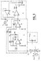
- FIG. 3 represents the detailed diagram of the measurement device of FIG. 2.
- FIG. 4 represents the waveforms which can be observed at various points of the circuit shown diagrammatically in FIG. 3.
- the measurement device intended to be connected in series between a generator G and a user device U, comprises a sensor for intensity 1 which, crossed by the current I whose peak value must be determined, delivers an alternating signal whose voltage is at each instant proportional to the intensity of said current.
- the voltage of this signal changes in the same way as the intensity of the current, the variations of which are shown in FIG. 1.
- the alternating signal delivered by the sensor 1 is applied to a double rectifier. alternation 2 which delivers a rectified signal formed of alternations of the same polarity whose amplitude corresponds to that of the positive and negative alternations of the output signal of the sensor 1.
- the rectified signal is received by a peak detector 3 which provides at its output a continuous signal whose amplitude, corresponding to the peak value of the rectified signal, is displayed by an indicator 4 such as a voltmeter.
- an indicator 4 such as a voltmeter.
- calibration means 5 are provided, which make it possible to adjust the device so that the indicator displays 100% when the peak value of the current I reaches the limit value of the instantaneous current which can be supplied by the generator used in each particular case.
- the sensor 1 comprises a current step-down current transformer 6, the primary of which is connected to input terminals E o , E 1 allowing its insertion into the power circuit of the electric generator and the secondary is connected to a shunt 7, i.e. to a resistor of low value, at the terminals of which develops a voltage signal V A representative of the intensity I circulating in the primary.
- This signal V A is available on terminal A of shunt 7, the other terminal of which is grounded to the device.
- the transformer 6 can be omitted, the current I being directly injected into the shunt 7, which then similarly delivers the aforementioned signal V A.
- the insulation provided by the transformer 6 between the power circuit and the measurement device disappears, which possibly constitutes a drawback.
- the terminal A of the shunt 7 is connected, via a switch 10, to the input terminal E 2 of the full-wave rectifier 2.
- the latter is of the so-called no threshold type, that is to say that the threshold at beyond which it begins to supply an output voltage when the input voltage crosses the zero level is of zero value.
- It comprises two operational amplifiers 20, 21.
- the inverting input of the first amplifier 20 is connected to the input E 2 via a resistor R 20 and to its output via a resistor R 21 in series with a diode D 21 and via a resistor R 22 in series with a diode D 22 .
- These two diodes are arranged in opposite directions, the diode D 21 being connected by its cathode to the output S and the diode D 22 by its anode.
- the inverting input of the second amplifier 21 is connected by a resistor R 23 to the point B common to the resistor R 21 and the diode D 21 and, by a resistor R 24 , to the input E 2 of the rectifier 2.
- the amplifier 21 is also looped by a variable resistor R 25 connected between its inverting input and its output, which constitutes the output S 2 of the rectifier 2.
- the peak detector 3 comprises a first operational amplifier 30 whose non-inverting input is connected to the output S 2 of the rectifier 2 and whose output is connected to the anode of a diode D 30 whose cathode is connected to a terminal of a capacitor C, the other terminal of which is connected to ground. In parallel with this capacitor is connected a resistor R 30 .
- the point D common to the diode D 30 , to the capacitor C and to the resistor R 30 is connected to the non-inverting input of the second amplifier 31 looped in unity gain, the output S 3 of which is connected to the inverting input of the first amplifier 30, as well as to a voltmeter 4 displaying the voltage present at the output of the amplifier 31.
- the rectified signal Vr is applied to the peak detector 3 where it charges the capacitor C via the amplifier 30 and the diode D 30 .
- the voltage V D which results therefrom on this capacitor is found to be identical, via the amplifier 31 offering a gain + 1, on the inverting input of the amplifier 30. Furthermore, between each charge period of the capacitor C under the effect of the alternations of the signal Vr, this capacitor discharges slowly in resistance R 30 (with a time constant of the order of a few seconds). Consequently, when the signal Vr is greater than the signal V D , the amplifier supplies a positive output voltage which charges the capacitor C via the diode D 30 made conductive.
- the amplifier 30 supplies at its output a negative voltage which blocks the diode D 30 , so that the capacitor C continues to discharge in the resistor R 30 , the voltage of the signal V D decreasing slowly until it becomes lower than the peak voltage of the signal Vr, in which case the charge of the capacitor C resumes.
- the voltmeter 4 connected to the output S 3 of the amplifier 31 and thus giving the measurement of the voltage of the signal V D , indicates a value proportional to the peak value of the current I.
- This indication can be provided in percentage, the 0% graduation corresponding to a zero current I, therefore at a zero charge rate for the generator, and the 100% graduation to a current I whose peaks reach their maximum level compatible with the characteristics of the generator therefore with the rate maximum load thereof.
- the calibration means 5 comprise a potentiometer P to which is applied a very stable reference voltage Vref generated by a special circuit not shown. Thanks to the switch 10, the input E 2 of the rectifier 2 can be connected either to point A, for a peak intensity measurement, or to the cursor of the potentiometer P, for a calibration. In the latter case, the potentiometer P is adjusted so that the voltage at point E 2 is equal to the peak voltage which would appear at point A if the electric generator used delivered the maximum peak intensity that it is capable of supplying . Then we adjust the variable resistance R 25 which adjusts the gain of amplifier 21 so that the voltmeter displays its maximum indication (100%). Point E 2 is then connected to point A by actuation of switch 10, and measurement of the generator charge rate can begin.
- Vref very stable reference voltage
Landscapes
- Engineering & Computer Science (AREA)
- Power Engineering (AREA)
- Physics & Mathematics (AREA)
- General Physics & Mathematics (AREA)
- Measurement Of Current Or Voltage (AREA)
- Catching Or Destruction (AREA)
Claims (7)
- Vorrichtung zur Messung des tatsächlichen Lastfaktors eines elektrischen Wechselstromgenerators, der ein Verbrauchsgerät speist,- mit einer Strommeßsonde (1), die ein zur Stärke des vom Generator abgegebenen Stroms (I) permanent proportionales Signal (VA) liefert,- mit einem Gleichrichterkreis (2), der dieses Signal empfängt und ein gleichgerichtetes Signal (Vr) liefert,- und mit Eichmitteln (5),dadurch gekennzeichnet,- daß die Meßvorrichtung eine Spitzenwert-Detektorschaltung (3) aufweist, die das gleichgerichtete Signal empfängt und daraus den Spitzenwert (VD) zur Anzeige in einem Anzeigeorgan (4) entnimmt,- und daß die Eichmittel (5) eine Regelung der Meßvorrichtung so ermöglichen, daß das Anzeigeorgan (4) für den Spitzenwert 100% anzeigt, wenn der Spitzenwert des gemessenen Wechselstroms den vorgeschriebenen Maximalpegel erreicht.
- Vorrichtung nach Anspruch 1, dadurch gekennzeichnet, daß die Strommeßsonde (1) von einem Widerstand gebildet wird, der von dem zu messenden Strom (I) durchflossen wird.
- Vorrichtung nach Anspruch 1, dadurch gekennzeichnet, daß die Strommeßsonde von einem Stromtransformator (6) gebildet wird, der von einem Widerstand (7) abgeschlossen wird.
- Vorrichtung nach einem beliebigen der Ansprüche 1 bis 3, dadurch gekennzeichnet, daß die Gleichrichterschaltung (2) keinen Schwellwert besitzt.
- Vorrichtung nach einem beliebigen der Ansprüche 1 bis 4, dadurch gekennzeichnet, daß die Gleichrichterschaltung eine Zweiweg-Gleichrichtung bewirkt.
- Vorrichtung nach Anspruch 5, dadurch gekennzeichnet, daB die Gleichrichterschaltung einen Einweg-Gleichrichter gefolgt von einem Summierglied enthält, das dem Ausgangssignal des Gleichrichters die Hälfte des Eingangssignals nochmals hinzufügt.
- Vorrichtung nach einem beliebigen der Ansprüche 1 bis 6, dadurch gekennzeichnet, daß die Spitzenwert-Detektorschaltung (4) einen Komparatorverstärker (30) enthält, dessen Ausgang über eine Diode (D30) an die Parallelschaltung eines Kondensators (C) und eines Widerstands (R30) angeschlossen ist, und der an einem Eingang das Ausgangssignal (Vr) des Gleichrichters empfängt und mit seinem anderen Eingang über einen Einheitsverstärker (31) an den Kondensator angeschlossen ist.
Applications Claiming Priority (2)
| Application Number | Priority Date | Filing Date | Title |
|---|---|---|---|
| FR9114558 | 1991-11-26 | ||
| FR9114558A FR2684188B1 (fr) | 1991-11-26 | 1991-11-26 | Dispositif de mesure du taux de charge reel d'un generateur electrique. |
Publications (2)
| Publication Number | Publication Date |
|---|---|
| EP0544589A1 EP0544589A1 (de) | 1993-06-02 |
| EP0544589B1 true EP0544589B1 (de) | 1997-09-10 |
Family
ID=9419326
Family Applications (1)
| Application Number | Title | Priority Date | Filing Date |
|---|---|---|---|
| EP92403169A Expired - Lifetime EP0544589B1 (de) | 1991-11-26 | 1992-11-25 | Gerät zur Messung des realen Lastfaktors eines elektrischen Generators |
Country Status (6)
| Country | Link |
|---|---|
| US (1) | US5471134A (de) |
| EP (1) | EP0544589B1 (de) |
| CA (1) | CA2083753A1 (de) |
| DE (1) | DE69222120T2 (de) |
| ES (1) | ES2104873T3 (de) |
| FR (1) | FR2684188B1 (de) |
Families Citing this family (9)
| Publication number | Priority date | Publication date | Assignee | Title |
|---|---|---|---|---|
| DE4243914A1 (de) * | 1992-12-23 | 1994-06-30 | Siemens Ag | Verfahren und Einrichtung zum Bestimmen der Wirkleistung eines elektrischen Antriebs |
| US5805856A (en) * | 1996-05-03 | 1998-09-08 | Jeffrey H. Hanson | Supplemental heating system |
| US5905439A (en) * | 1997-09-02 | 1999-05-18 | Eastman Kodak Company | Apparatus and method for monitoring a plurality of parallel loads having a common supply |
| DE10151065A1 (de) * | 2001-10-16 | 2003-04-17 | Bosch Gmbh Robert | Verfahren/Vorrichtung zur Überwachung eines Verbrauchers |
| KR100449801B1 (ko) * | 2002-10-31 | 2004-09-22 | 한국전력공사 | 디지털 저압 최대전류 측정기 |
| US7460602B2 (en) * | 2005-04-29 | 2008-12-02 | International Business Machines Corporation | Method for performing high speed serial link output stage having self adaptation for various impairments |
| US9804204B2 (en) * | 2011-09-21 | 2017-10-31 | Honeywell International Inc. | Method of implementation of peak hold in a phasing voltmeter |
| CN104297551B (zh) * | 2014-09-26 | 2017-02-15 | 中国电子科技集团公司第十三研究所 | 一种皮纳安级直流电流源高精度校准系统 |
| EP3179258A1 (de) * | 2015-12-10 | 2017-06-14 | ABB Schweiz AG | Elektrische installationsvorrichtung mit strommessschaltung |
Family Cites Families (7)
| Publication number | Priority date | Publication date | Assignee | Title |
|---|---|---|---|---|
| NL6600236A (de) * | 1966-01-08 | 1967-07-10 | ||
| DE1588373A1 (de) * | 1967-08-25 | 1970-12-10 | Kirsch Fa Bernhard | Vorrichtung zum Messen der Generatorbelastung |
| US4333049A (en) * | 1979-05-21 | 1982-06-01 | Takamisawa Cybernetics Co., Ltd. | Inrush current measuring apparatus with instantaneous power interruption device |
| US4639618A (en) * | 1983-09-26 | 1987-01-27 | Pace, Incorporated | Spike detector circuitry |
| DE3728163C2 (de) * | 1987-08-24 | 1998-05-20 | Messwandler Bau Ag | Meßeinrichtung zur Bestimmung des Scheitelwerts hoher Wechselspannungen |
| US4884019A (en) * | 1988-01-29 | 1989-11-28 | In-Situ, Inc. | Accurate analog measurement system |
| DE69025474T2 (de) * | 1990-10-24 | 1996-09-19 | Ibm | Strom-Spannungswandler mit niedrigem Rauschen, hoher Bandbreite und hoher Dynamik |
-
1991
- 1991-11-26 FR FR9114558A patent/FR2684188B1/fr not_active Expired - Fee Related
-
1992
- 1992-11-24 US US07/980,970 patent/US5471134A/en not_active Expired - Fee Related
- 1992-11-25 EP EP92403169A patent/EP0544589B1/de not_active Expired - Lifetime
- 1992-11-25 ES ES92403169T patent/ES2104873T3/es not_active Expired - Lifetime
- 1992-11-25 DE DE69222120T patent/DE69222120T2/de not_active Expired - Fee Related
- 1992-11-25 CA CA002083753A patent/CA2083753A1/fr not_active Abandoned
Also Published As
| Publication number | Publication date |
|---|---|
| FR2684188B1 (fr) | 1997-12-05 |
| ES2104873T3 (es) | 1997-10-16 |
| DE69222120T2 (de) | 1998-01-22 |
| CA2083753A1 (fr) | 1993-05-27 |
| EP0544589A1 (de) | 1993-06-02 |
| FR2684188A1 (fr) | 1993-05-28 |
| DE69222120D1 (de) | 1997-10-16 |
| US5471134A (en) | 1995-11-28 |
Similar Documents
| Publication | Publication Date | Title |
|---|---|---|
| EP0297933A1 (de) | Anordnung zur Kontrolle und zur Messung der Isolierung eines elektrischen Netzes | |
| EP0892273B1 (de) | Versorgungsschaltung für einen Elektizitätszähler | |
| FR3042603A1 (fr) | Dispositif de controle pour un parafoudre et systeme de controle comportant un dispositif de controle | |
| FR2872913A1 (fr) | Procede de determination des composantes active et reactive de l'impedance de boucle d'un reseau d'alimentation en courant alternatif, ainsi qu'un dispositif pour la mise en oeuvre de ce procede | |
| EP0544589A1 (de) | Gerät zur Messung des realen Lastfaktors eines elektrischen Generators | |
| EP4169137B1 (de) | Verfahren zur erkennung von leck- oder fehlerströmen in einer elektrischen anlage mit einer schutzvorrichtung | |
| EP3462187A1 (de) | Spannungspräsenz-anzeigesystem in einem hochspannungsnetz | |
| FR2490347A1 (fr) | Procede et dispositif pour controler des structures protegees cathodiquement | |
| EP0354841B1 (de) | Überwachungsanordnung für die Unausgeglichenheit der elektrischen Leistung in einem elektrischen Netz oder einer Installation | |
| FR2671190A1 (fr) | Pont de mesure de tension de reference pour dispositif de controle et de mesure de l'isolement d'un reseau electrique a tension continue. | |
| EP0592337B1 (de) | Elektronischer Auslöser mit Erdschutz | |
| EP0489665B1 (de) | Anordnung zur Isolationskontrolle mit erhöhter Genauigkeit | |
| FR2489197A1 (fr) | Circuit de surveillance pour appareil de soudage electrique | |
| JPS6256870A (ja) | 避雷器の劣化検出装置 | |
| US6448780B1 (en) | Method of calculating a resistance | |
| EP0678751B1 (de) | Detektorvorrichtung für Änderungen einer Versorgungsspannung | |
| EP0454542B1 (de) | Kontrollvorrichtung, die zur Messung der Wirksamkeit eines elektrischen Zaunes dient | |
| WO2021234240A1 (fr) | Mesure de la tension dans un câble mono-conducteur isolé | |
| EP2863232A1 (de) | Verfahren zur Bestimmung eines individuellen Leistungsverbrauchs | |
| FR2562258A1 (fr) | Dispositif de mesure de l'impedance des prises de terre | |
| FR2694409A1 (fr) | Dispositif de détection de défauts sur un réseau de distribution d'énergie électrique souterrain. | |
| FR2630548A1 (fr) | Dispositif de mesure de resistance electrique | |
| FR2471607A1 (fr) | Sonde de tension, pour distinguer les conducteurs de phase et de neutre sur des installations a basse tension par detection du courant capacitif vers la terre a travers le corps d'un operateur | |
| EP0597897A1 (de) | Anordnung zum speisen einer nichtlinearen ladung. | |
| FR2482803A1 (fr) | Generateur de signaux fonctions d'un courant de donnee, alimente par ce courant, et application aux relais de courant |
Legal Events
| Date | Code | Title | Description |
|---|---|---|---|
| PUAI | Public reference made under article 153(3) epc to a published international application that has entered the european phase |
Free format text: ORIGINAL CODE: 0009012 |
|
| AK | Designated contracting states |
Kind code of ref document: A1 Designated state(s): DE ES FR GB IT NL |
|
| 17P | Request for examination filed |
Effective date: 19931004 |
|
| 17Q | First examination report despatched |
Effective date: 19960430 |
|
| GRAG | Despatch of communication of intention to grant |
Free format text: ORIGINAL CODE: EPIDOS AGRA |
|
| GRAH | Despatch of communication of intention to grant a patent |
Free format text: ORIGINAL CODE: EPIDOS IGRA |
|
| GRAH | Despatch of communication of intention to grant a patent |
Free format text: ORIGINAL CODE: EPIDOS IGRA |
|
| GRAA | (expected) grant |
Free format text: ORIGINAL CODE: 0009210 |
|
| RAP1 | Party data changed (applicant data changed or rights of an application transferred) |
Owner name: ALCATEL ALSTHOM COMPAGNIE GENERALE D'ELECTRICITE |
|
| AK | Designated contracting states |
Kind code of ref document: B1 Designated state(s): DE ES FR GB IT NL |
|
| ITF | It: translation for a ep patent filed | ||
| GBT | Gb: translation of ep patent filed (gb section 77(6)(a)/1977) |
Effective date: 19970915 |
|
| REF | Corresponds to: |
Ref document number: 69222120 Country of ref document: DE Date of ref document: 19971016 |
|
| REG | Reference to a national code |
Ref country code: ES Ref legal event code: FG2A Ref document number: 2104873 Country of ref document: ES Kind code of ref document: T3 |
|
| PLBE | No opposition filed within time limit |
Free format text: ORIGINAL CODE: 0009261 |
|
| STAA | Information on the status of an ep patent application or granted ep patent |
Free format text: STATUS: NO OPPOSITION FILED WITHIN TIME LIMIT |
|
| 26N | No opposition filed | ||
| PGFP | Annual fee paid to national office [announced via postgrant information from national office to epo] |
Ref country code: GB Payment date: 19991012 Year of fee payment: 8 |
|
| PGFP | Annual fee paid to national office [announced via postgrant information from national office to epo] |
Ref country code: NL Payment date: 19991014 Year of fee payment: 8 |
|
| PGFP | Annual fee paid to national office [announced via postgrant information from national office to epo] |
Ref country code: DE Payment date: 19991025 Year of fee payment: 8 |
|
| PGFP | Annual fee paid to national office [announced via postgrant information from national office to epo] |
Ref country code: FR Payment date: 19991027 Year of fee payment: 8 |
|
| PGFP | Annual fee paid to national office [announced via postgrant information from national office to epo] |
Ref country code: ES Payment date: 19991117 Year of fee payment: 8 |
|
| PG25 | Lapsed in a contracting state [announced via postgrant information from national office to epo] |
Ref country code: GB Free format text: LAPSE BECAUSE OF NON-PAYMENT OF DUE FEES Effective date: 20001125 |
|
| PG25 | Lapsed in a contracting state [announced via postgrant information from national office to epo] |
Ref country code: ES Free format text: LAPSE BECAUSE OF NON-PAYMENT OF DUE FEES Effective date: 20001126 |
|
| PG25 | Lapsed in a contracting state [announced via postgrant information from national office to epo] |
Ref country code: NL Free format text: LAPSE BECAUSE OF NON-PAYMENT OF DUE FEES Effective date: 20010601 |
|
| GBPC | Gb: european patent ceased through non-payment of renewal fee |
Effective date: 20001125 |
|
| PG25 | Lapsed in a contracting state [announced via postgrant information from national office to epo] |
Ref country code: FR Free format text: LAPSE BECAUSE OF NON-PAYMENT OF DUE FEES Effective date: 20010731 |
|
| NLV4 | Nl: lapsed or anulled due to non-payment of the annual fee |
Effective date: 20010601 |
|
| PG25 | Lapsed in a contracting state [announced via postgrant information from national office to epo] |
Ref country code: DE Free format text: LAPSE BECAUSE OF NON-PAYMENT OF DUE FEES Effective date: 20010801 |
|
| REG | Reference to a national code |
Ref country code: FR Ref legal event code: ST |
|
| REG | Reference to a national code |
Ref country code: ES Ref legal event code: FD2A Effective date: 20011214 |
|
| PG25 | Lapsed in a contracting state [announced via postgrant information from national office to epo] |
Ref country code: IT Free format text: LAPSE BECAUSE OF NON-PAYMENT OF DUE FEES Effective date: 20051125 |