EP0092002B1 - Brennstoffzerstäuber für Ölbrenner - Google Patents
Brennstoffzerstäuber für Ölbrenner Download PDFInfo
- Publication number
- EP0092002B1 EP0092002B1 EP82302010A EP82302010A EP0092002B1 EP 0092002 B1 EP0092002 B1 EP 0092002B1 EP 82302010 A EP82302010 A EP 82302010A EP 82302010 A EP82302010 A EP 82302010A EP 0092002 B1 EP0092002 B1 EP 0092002B1
- Authority
- EP
- European Patent Office
- Prior art keywords
- oil
- mixing chamber
- ports
- burner
- exit
- Prior art date
- Legal status (The legal status is an assumption and is not a legal conclusion. Google has not performed a legal analysis and makes no representation as to the accuracy of the status listed.)
- Expired
Links
Images
Classifications
-
- F—MECHANICAL ENGINEERING; LIGHTING; HEATING; WEAPONS; BLASTING
- F23—COMBUSTION APPARATUS; COMBUSTION PROCESSES
- F23D—BURNERS
- F23D11/00—Burners using a direct spraying action of liquid droplets or vaporised liquid into the combustion space
- F23D11/10—Burners using a direct spraying action of liquid droplets or vaporised liquid into the combustion space the spraying being induced by a gaseous medium, e.g. water vapour
- F23D11/101—Burners using a direct spraying action of liquid droplets or vaporised liquid into the combustion space the spraying being induced by a gaseous medium, e.g. water vapour medium and fuel meeting before the burner outlet
- F23D11/102—Burners using a direct spraying action of liquid droplets or vaporised liquid into the combustion space the spraying being induced by a gaseous medium, e.g. water vapour medium and fuel meeting before the burner outlet in an internal mixing chamber
- F23D11/103—Burners using a direct spraying action of liquid droplets or vaporised liquid into the combustion space the spraying being induced by a gaseous medium, e.g. water vapour medium and fuel meeting before the burner outlet in an internal mixing chamber with means creating a swirl inside the mixing chamber
Definitions
- This invention relates to oil fuel atomisers for use in oil burners.
- an atomiser for an oil burner comprising a body having an exit leading outwardly from an annular mixing region, means for injecting oil through oil inlet ports into the mixing region and means for injecting an atomising fluid into the mixing region at a plurality of positions in a wall of the mixing region to form an oil spray.
- the mixing region is an annular groove.
- a common practice in oil burners for large boilers is to use atomisers of the Y-jet type in which a number of ports are arranged at an angle to the burner axis to produce a hollow conical spray.
- Each exit port has a co-axial atomising fluid port for injection of the atomising fluid (which may be steam or air) and also has an oil port entering at an angle.
- a degree of mixing between the atomising fluid and oil takes place in the exit port and the two phase mixture then expands out of the exit port to form a spray.
- One of the problems with this type of atomiser is that the jet of oil from the oil port tends to impinge on the opposite side of the exit port where it forms a thick film. This thick film can persist through the exit port to the end thereof and hence lead to the formation of relatively large oil droplets.
- a multi-jet atomiser for an oil burner comprises a body having a plurality of exit ports leading outwardly from an annular mixing chamber to form a hollow conical spray, means for injecting oil through oil inlet ports into the mixing chamber, the oil being injected at each inlet port in a direction to produce a toroidal recirculation in the annular mixing chamber with the injected oil from each inlet port passing close to an exit port at approximately right angles to the axis of that exit port and means for injecting an atomising fluid into the mixing chamber at a plurality of positions in a wall of the mixing chamber.
- the atomising fluid is injected into a turbulent recirculating flow region through ports in the wall of the mixing chamber opposite the exit ports.
- the atomising fluid thus becomes well mixed with the oil and carries part of the recirculating mixture into the exit ports in the appropriate directions to pass through these ports and to expand outwardly therefrom as a fine spray.
- a plenum chamber or a plurality of plenum chambers through which the oil is fed into the aforementioned oil inlet ports.
- the aforementioned annular mixing chamber preferably has a curved surface opposite each oil injection port shaped to direct the impinging oil around a curved path towards the axis of the burner assembly and hence to promote the toroidal recirculation.
- the aforesaid means for injecting an atomising fluid into the mixing chamber may be at a plurality of positions in a wall of the mixing chamber opposite the exit ports.
- the mixing chamber may have walls shaped to guide the injected oil in a direction across the exit ports and thence around in a recirculatory path over the wall opposite the exit ports.
- the annular mixing chamber and, if provided, the plenum chamber or chambers are constituted by regions between the end of a main burner body element containing a central atomising fluid passage extending axially through the body element to atomising fluid injection ports in the end thereof and a cap which is secured, e.g. threaded, onto the main burner body element and which has the aforesaid exit ports.
- the main burner body element may contain a central oil passage extending axially through the body element to said oil inlet ports.
- the atomising fluid is passed through passages around the central oil passage.
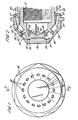
- the atomiser has a main elongate body member 10 with a central passage 11 extending axially through the member 10 towards the end thereof to carry an atomising fluid, either steam or air.
- This passage 11 terminates in a frusto conical face 12 from which a number of ports 13 extend, these ports leading into an annular mixing chamber 15.
- This mixing chamber has a plurality of exit ports 14 as seen most clearly in Figure 1.
- These ports 14 are formed in cap member 16, internally threaded at 17, which fits over the end of the body member 10.
- the ports 13 and the ports 14 are at angles of about 45° to the axis of the assembly. These ports 13 and 14 need not necessarily be at the same angle to the axis of the assembly. The angles for the exit ports 14 would depend on the desired cone angle of the spray. In some cases it may be preferred to make the inlet ports 13 parallel to the axis of the assembly.
- Oil from an annular region 20 around the outside of the body member 10 passes through a plurality of oil ducts 21 in the cap member 16, into an annular plenum chamber 22. From the plenum chamber, the oil is injected into a mixing chamber 15 through a ring of ports 23 through an upstanding part 24 in the body member 10. The injection from the ports 23 into the mixing chamber is in a direction such as to produce a toroidal circulation of the oil in the mixing chamber 15.
- the oil ports 23 are arranged to produce oil jets which pass close to the exit ports 14 at approximately right angles to the axis of the exit ports.
- the plenum chamber 22 and mixing chamber 15 are formed as gaps between the cap member 16 and the main body member 10.
- the shaping of these members 10, 16 is such that, when the cap member is screwed in position on the body member, the gaps between the cap member and body member form the mixing chamber and plenum chamber.
- the exit ports 14 have their axes defining a cone, the axis of this cone being aligned with the longitudinal axis of the burner and the apex of the cone being on that longitudinal axis.
- the oil spray from the plurality of exit ports 14 thus is in the general form of a hollow cone.
- the atomising fluid is injected through ports on the opposite wall of the chamber, that is the wall facing the exit ports. This wall is conical. It is not necessary in this construction however that the cap member 16 is angularly aligned with respect to the body element 10. Alignment of the injection ports and exit ports is not critical and, in the particular embodiment illustrated, there are two rows of injection ports 13 and one row of exit ports 14. The fluid entering the exit ports is well mixed in the mixing chamber and is forced into the exit ports. This construction gives good atomisation.
- the simple construction having a cap 16 screwed onto the body member 10 enables the atomiser to be easily cleaned after these parts are separated.
- the exit ports 14 are evenly spaced with their axes lying on the same cone. In some cases, however, it may be advantageous to have these exit ports on more than one cone.
- the ports 14 need not necessarily be evenly spaced; they may be irregularly spaced or grouped.
- the atomising fluid ports are directly opposite and pointing towards the exit ports.
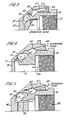
- Figure 3 illustrates a modification of that construction and the same reference characters are used to indicate corresponding components.
- the atomising fluid inlets to the mixing chamber, as shown at 30, produce atomising fluid jets which tend to counter the toroidal circulation produced by the oil jets 23. This may be advantageous in some cases to enhance mixing with the oil.
- the inlets to the atomising fluid ports 30 are at a greater distance from the atomiser axis than in the arrangement of Figures 1 and 2, it is easier to provide the requisite number of ports.
- the atomising fluid is fed axially through a central passage 11 in the main burner body 10.
- it may be preferred to reverse the position of the oil and atomising fluid feeds the oil feed being axially through a passage 41 and the atomising fluid being from an annular region 42 around the outside of the body member 10.
- This arrangement makes the incorporation of sufficient atomising fluid port area much easier by locating these ports as far as possible from the atomiser axis.
- the fact that the oil ports shown at 43 in Figure 4 are now much closer to the axis is not too much of an imposition because the total oil port area is generally significantly less than the total atomising fluid port area.
- Figure 5 illustrates a modification of Figure 4 in which the oil ports, shown at 50, are approximately parallel to the atomiser axis.
- the mixing chamberwall is shaped to direct the oil jets across the approach region to the exit ports. This arrangement may simplify manufacture.
Landscapes
- Engineering & Computer Science (AREA)
- Chemical & Material Sciences (AREA)
- Combustion & Propulsion (AREA)
- Mechanical Engineering (AREA)
- General Engineering & Computer Science (AREA)
- Nozzles For Spraying Of Liquid Fuel (AREA)
Claims (10)
Priority Applications (3)
| Application Number | Priority Date | Filing Date | Title |
|---|---|---|---|
| DE8282302010T DE3267989D1 (en) | 1982-04-20 | 1982-04-20 | Fuel atomisers for oil burners |
| AT82302010T ATE17030T1 (de) | 1982-04-20 | 1982-04-20 | Brennstoffzerstaeuber fuer oelbrenner. |
| EP82302010A EP0092002B1 (de) | 1982-04-20 | 1982-04-20 | Brennstoffzerstäuber für Ölbrenner |
Applications Claiming Priority (1)
| Application Number | Priority Date | Filing Date | Title |
|---|---|---|---|
| EP82302010A EP0092002B1 (de) | 1982-04-20 | 1982-04-20 | Brennstoffzerstäuber für Ölbrenner |
Publications (2)
| Publication Number | Publication Date |
|---|---|
| EP0092002A1 EP0092002A1 (de) | 1983-10-26 |
| EP0092002B1 true EP0092002B1 (de) | 1985-12-18 |
Family
ID=8189639
Family Applications (1)
| Application Number | Title | Priority Date | Filing Date |
|---|---|---|---|
| EP82302010A Expired EP0092002B1 (de) | 1982-04-20 | 1982-04-20 | Brennstoffzerstäuber für Ölbrenner |
Country Status (3)
| Country | Link |
|---|---|
| EP (1) | EP0092002B1 (de) |
| AT (1) | ATE17030T1 (de) |
| DE (1) | DE3267989D1 (de) |
Families Citing this family (5)
| Publication number | Priority date | Publication date | Assignee | Title |
|---|---|---|---|---|
| JPS60126511A (ja) * | 1983-12-09 | 1985-07-06 | Haruji Kurogo | 霧化を促進し燃焼を改善するバ−ナ−・チップ装置 |
| DE3669915D1 (de) * | 1986-11-27 | 1990-05-03 | Fluidics Instr Bv | Druckluftzerstaeuberduese. |
| DE3762288D1 (de) * | 1987-02-13 | 1990-05-17 | Bbc Brown Boveri & Cie | Zerstaeuberduese. |
| GB8905835D0 (en) * | 1989-03-14 | 1989-04-26 | British Petroleum Co Plc | Spray nozzle |
| JP2537411B2 (ja) * | 1989-09-20 | 1996-09-25 | 日本石油株式会社 | 液体燃料燃焼用バ―ナ― |
Family Cites Families (6)
| Publication number | Priority date | Publication date | Assignee | Title |
|---|---|---|---|---|
| US1785802A (en) * | 1923-11-16 | 1930-12-23 | Adams Henry | Atomizing jet nozzle |
| US1785804A (en) * | 1924-06-17 | 1930-12-23 | Adams Henry | Process for oil burning |
| GB1424191A (en) * | 1972-01-15 | 1976-02-11 | Secr Defence | Fuel burning apparatus |
| FR2288940A1 (fr) * | 1974-10-24 | 1976-05-21 | Pillard Chauffage | Perfectionnements aux bruleurs de combustibles liquides pulverises par la detente d'un fluide auxiliaire et procede d'utilisation de ceux-ci |
| GB1470671A (en) * | 1975-07-07 | 1977-04-21 | Central Electr Generat Board | Oil fuel atomisers for boilers |
| US4141505A (en) * | 1976-06-07 | 1979-02-27 | Reich Richard B | Heavy fuel oil nozzle |
-
1982
- 1982-04-20 EP EP82302010A patent/EP0092002B1/de not_active Expired
- 1982-04-20 DE DE8282302010T patent/DE3267989D1/de not_active Expired
- 1982-04-20 AT AT82302010T patent/ATE17030T1/de not_active IP Right Cessation
Also Published As
| Publication number | Publication date |
|---|---|
| EP0092002A1 (de) | 1983-10-26 |
| DE3267989D1 (en) | 1986-01-30 |
| ATE17030T1 (de) | 1986-01-15 |
Similar Documents
| Publication | Publication Date | Title |
|---|---|---|
| DE69827897T2 (de) | Zweistoffdüse zur Verhinderung der kohlenstoffhaltigen Ablagerung auf Oberflächen einer Gasturbinenbrennkammer | |
| US3692245A (en) | Fluid atomizers | |
| US4087050A (en) | Swirl type pressure fuel atomizer | |
| US4011996A (en) | Swirl type pressure fuel atomizer | |
| US5697553A (en) | Streaked spray nozzle for enhanced air/fuel mixing | |
| DE69718253T2 (de) | Vorrichtung zur Einspritzung von mit Luft zerstäubten Einzelstrahlen aus flüssigem Brennstoff | |
| US4890793A (en) | Atomizer nozzle | |
| US4595143A (en) | Air swirl nozzle | |
| US5622489A (en) | Fuel atomizer and apparatus and method for reducing NOx | |
| DE2641685A1 (de) | Niederdruck-brennstoff-injektionszerstaeubersystem | |
| DE2345282B2 (de) | Verbrennungseinrichtung für Gasturbinentriebwerke | |
| JPH0787907B2 (ja) | 改良されたスプレーノズルデザイン | |
| US5573392A (en) | Method and device for distributing fuel in a burner suitable for both liquid and gaseous fuels | |
| US3968644A (en) | Fuel admitting and conditioning means on combustion chambers for gas turbine engines | |
| US3581495A (en) | Slot tube swirler injector | |
| IT9009352A1 (it) | Atomizzatore perfezionato per combustibili liquidi viscosi | |
| EP0092002B1 (de) | Brennstoffzerstäuber für Ölbrenner | |
| US5588824A (en) | Injection nozzle | |
| US2567485A (en) | Gas-burner head with high-pressure air jets | |
| US5738509A (en) | Premix burner having axial or radial air inflow | |
| US1529531A (en) | Spray nozzle | |
| US6036479A (en) | Two-stage pressure atomizer nozzle | |
| US3039701A (en) | Fuel injectors | |
| GB2084903A (en) | Atomising liquid fuel | |
| US4516728A (en) | Liquid fuel atomizer |
Legal Events
| Date | Code | Title | Description |
|---|---|---|---|
| PUAI | Public reference made under article 153(3) epc to a published international application that has entered the european phase |
Free format text: ORIGINAL CODE: 0009012 |
|
| 17P | Request for examination filed |
Effective date: 19830203 |
|
| AK | Designated contracting states |
Designated state(s): AT BE CH DE FR IT LI LU NL SE |
|
| GRAA | (expected) grant |
Free format text: ORIGINAL CODE: 0009210 |
|
| AK | Designated contracting states |
Designated state(s): AT BE CH DE FR IT LI LU NL SE |
|
| REF | Corresponds to: |
Ref document number: 17030 Country of ref document: AT Date of ref document: 19860115 Kind code of ref document: T |
|
| REF | Corresponds to: |
Ref document number: 3267989 Country of ref document: DE Date of ref document: 19860130 |
|
| ET | Fr: translation filed | ||
| ITF | It: translation for a ep patent filed | ||
| PLBE | No opposition filed within time limit |
Free format text: ORIGINAL CODE: 0009261 |
|
| STAA | Information on the status of an ep patent application or granted ep patent |
Free format text: STATUS: NO OPPOSITION FILED WITHIN TIME LIMIT |
|
| 26N | No opposition filed | ||
| ITTA | It: last paid annual fee | ||
| EPTA | Lu: last paid annual fee | ||
| EAL | Se: european patent in force in sweden |
Ref document number: 82302010.2 |
|
| REG | Reference to a national code |
Ref country code: CH Ref legal event code: PUE Owner name: CENTRAL ELECTRICITY GENERATING BOARD TRANSFER- POW |
|
| REG | Reference to a national code |
Ref country code: FR Ref legal event code: TP |
|
| NLS | Nl: assignments of ep-patents |
Owner name: POWERGEN PLC, |
|
| BECA | Be: change of holder's address |
Free format text: 980223 *POWERGEN PLC:NEW BROAD STREET 53, LONDON EC2M 1JJ |
|
| PGFP | Annual fee paid to national office [announced via postgrant information from national office to epo] |
Ref country code: SE Payment date: 19990408 Year of fee payment: 18 |
|
| PGFP | Annual fee paid to national office [announced via postgrant information from national office to epo] |
Ref country code: FR Payment date: 19990414 Year of fee payment: 18 Ref country code: CH Payment date: 19990414 Year of fee payment: 18 |
|
| PGFP | Annual fee paid to national office [announced via postgrant information from national office to epo] |
Ref country code: LU Payment date: 19990422 Year of fee payment: 18 |
|
| PGFP | Annual fee paid to national office [announced via postgrant information from national office to epo] |
Ref country code: NL Payment date: 19990429 Year of fee payment: 18 Ref country code: AT Payment date: 19990429 Year of fee payment: 18 |
|
| PGFP | Annual fee paid to national office [announced via postgrant information from national office to epo] |
Ref country code: BE Payment date: 19990503 Year of fee payment: 18 |
|
| PGFP | Annual fee paid to national office [announced via postgrant information from national office to epo] |
Ref country code: DE Payment date: 19990624 Year of fee payment: 18 |
|
| PG25 | Lapsed in a contracting state [announced via postgrant information from national office to epo] |
Ref country code: LU Free format text: LAPSE BECAUSE OF NON-PAYMENT OF DUE FEES Effective date: 20000420 Ref country code: AT Free format text: LAPSE BECAUSE OF NON-PAYMENT OF DUE FEES Effective date: 20000420 |
|
| PG25 | Lapsed in a contracting state [announced via postgrant information from national office to epo] |
Ref country code: SE Free format text: LAPSE BECAUSE OF NON-PAYMENT OF DUE FEES Effective date: 20000421 |
|
| PG25 | Lapsed in a contracting state [announced via postgrant information from national office to epo] |
Ref country code: LI Free format text: LAPSE BECAUSE OF NON-PAYMENT OF DUE FEES Effective date: 20000430 Ref country code: CH Free format text: LAPSE BECAUSE OF NON-PAYMENT OF DUE FEES Effective date: 20000430 Ref country code: BE Free format text: LAPSE BECAUSE OF NON-PAYMENT OF DUE FEES Effective date: 20000430 |
|
| BERE | Be: lapsed |
Owner name: POWERGEN PLC Effective date: 20000430 |
|
| PG25 | Lapsed in a contracting state [announced via postgrant information from national office to epo] |
Ref country code: NL Free format text: LAPSE BECAUSE OF NON-PAYMENT OF DUE FEES Effective date: 20001101 |
|
| EUG | Se: european patent has lapsed |
Ref document number: 82302010.2 |
|
| REG | Reference to a national code |
Ref country code: CH Ref legal event code: PL |
|
| PG25 | Lapsed in a contracting state [announced via postgrant information from national office to epo] |
Ref country code: FR Free format text: LAPSE BECAUSE OF NON-PAYMENT OF DUE FEES Effective date: 20001229 |
|
| NLV4 | Nl: lapsed or anulled due to non-payment of the annual fee |
Effective date: 20001101 |
|
| PG25 | Lapsed in a contracting state [announced via postgrant information from national office to epo] |
Ref country code: DE Free format text: LAPSE BECAUSE OF NON-PAYMENT OF DUE FEES Effective date: 20010201 |
|
| REG | Reference to a national code |
Ref country code: FR Ref legal event code: ST |