EP0091968B1 - Verdichter - Google Patents
Verdichter Download PDFInfo
- Publication number
- EP0091968B1 EP0091968B1 EP82903185A EP82903185A EP0091968B1 EP 0091968 B1 EP0091968 B1 EP 0091968B1 EP 82903185 A EP82903185 A EP 82903185A EP 82903185 A EP82903185 A EP 82903185A EP 0091968 B1 EP0091968 B1 EP 0091968B1
- Authority
- EP
- European Patent Office
- Prior art keywords
- vane
- suction
- compressor
- vane chamber
- pressure
- Prior art date
- Legal status (The legal status is an assumption and is not a legal conclusion. Google has not performed a legal analysis and makes no representation as to the accuracy of the status listed.)
- Expired
Links
- 238000011084 recovery Methods 0.000 claims description 16
- 239000012530 fluid Substances 0.000 claims description 9
- 239000003507 refrigerant Substances 0.000 description 26
- 238000001816 cooling Methods 0.000 description 7
- 238000000034 method Methods 0.000 description 6
- 238000011144 upstream manufacturing Methods 0.000 description 5
- 230000008859 change Effects 0.000 description 4
- 230000006835 compression Effects 0.000 description 4
- 238000007906 compression Methods 0.000 description 4
- 238000010276 construction Methods 0.000 description 4
- 238000007599 discharging Methods 0.000 description 4
- 238000010586 diagram Methods 0.000 description 3
- 230000001133 acceleration Effects 0.000 description 2
- 239000002826 coolant Substances 0.000 description 2
- 238000002474 experimental method Methods 0.000 description 2
- 230000002093 peripheral effect Effects 0.000 description 2
- 230000009467 reduction Effects 0.000 description 2
- 238000007792 addition Methods 0.000 description 1
- 230000003247 decreasing effect Effects 0.000 description 1
- 230000000694 effects Effects 0.000 description 1
- 230000020169 heat generation Effects 0.000 description 1
- 230000006872 improvement Effects 0.000 description 1
- 230000007246 mechanism Effects 0.000 description 1
- 230000001105 regulatory effect Effects 0.000 description 1
- 230000000630 rising effect Effects 0.000 description 1
- 229920006395 saturated elastomer Polymers 0.000 description 1
Images


Classifications
-
- F—MECHANICAL ENGINEERING; LIGHTING; HEATING; WEAPONS; BLASTING
- F04—POSITIVE - DISPLACEMENT MACHINES FOR LIQUIDS; PUMPS FOR LIQUIDS OR ELASTIC FLUIDS
- F04C—ROTARY-PISTON, OR OSCILLATING-PISTON, POSITIVE-DISPLACEMENT MACHINES FOR LIQUIDS; ROTARY-PISTON, OR OSCILLATING-PISTON, POSITIVE-DISPLACEMENT PUMPS
- F04C29/00—Component parts, details or accessories of pumps or pumping installations, not provided for in groups F04C18/00 - F04C28/00
- F04C29/12—Arrangements for admission or discharge of the working fluid, e.g. constructional features of the inlet or outlet
-
- F—MECHANICAL ENGINEERING; LIGHTING; HEATING; WEAPONS; BLASTING
- F04—POSITIVE - DISPLACEMENT MACHINES FOR LIQUIDS; PUMPS FOR LIQUIDS OR ELASTIC FLUIDS
- F04C—ROTARY-PISTON, OR OSCILLATING-PISTON, POSITIVE-DISPLACEMENT MACHINES FOR LIQUIDS; ROTARY-PISTON, OR OSCILLATING-PISTON, POSITIVE-DISPLACEMENT PUMPS
- F04C28/00—Control of, monitoring of, or safety arrangements for, pumps or pumping installations specially adapted for elastic fluids
- F04C28/18—Control of, monitoring of, or safety arrangements for, pumps or pumping installations specially adapted for elastic fluids characterised by varying the volume of the working chamber
Definitions
- the present invention relates to a rotary compressor and more particularly to a rotary compressor the refrigerative performance of which is arranged to be limited at high rates of rotation.
- a compressor comprises a rotor provided with slidably mounted vanes, a cylinder, side plates fixed to both ends of said cylinder and tightly enclosing a vane chamber defined by said rotor, vane, side plates and cylinder, and a suction groove and a suction port formed in said cylinder or side plate.
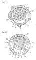
- a known type of sliding vane type rotary compressor is shown in Figure 1 and comprises a cylinder 51 having interior cylindrical space, side plates (not shown in Figure 1) fixed to both ends of the cylinder and forming parts of the walls of a vane chamber 52 within the cylinder, a rotor 53 which is arranged eccentrically within the cylinder 51, and a vane 55 which is engaged slidably within a groove 54 provided on the rotor 53.
- reference numeral 56 is a suction port formed in a side plate
- 57 is a discharge hole formed in the cylinder 1.
- the vane 55 is caused, by centrifugal force, to extend as the rotor 53 rotates, so that its tip slides on the interior wall face of the cylinder 1 thereby to prevent leakage of gas from the compressor.
- Sliding vane type rotary compressors are generally simpler in construction than a reciprocating type compressor, which is complex, with large numbers of parts. Sliding vane type rotary compressors are therefore suitable for use with car cooling systems. However there are a number of problems associated with sliding vane type rotary compressors.
- the present inventors have investigated in detail the transitional phenomena of pressure in the vane chamber when a rotary compressor is used, in order to overcome the problems in the refrigerative cycle for a car cooler, and as a result, it has been found that refrigerative performance limitation even at high rates of rotation can be effected even in the case of a rotary compressor, similarly to the customary reciprocating type, by selecting and suitably combining parameters such as area of suction port, discharging quantity, numbers of vane etc.
- ⁇ represents the angle (radian) formed around the centre of rotation of the rotor between the end of the vane closer to the cylinder and the cylinder top where the distance between the inner peripheral surface of the cylinder and the outer peripheral surface of the rotor is smallest;
- Vo represents the volume (cc) of the vane chamber when the rotation angle 6 is A 5 ;
- a(8) represents the effective area (cm 2 ) of the suction passage between an evaporator and the vane chamber.
- the refrigerating power is effectively suppressed in the high-speed operation without being accompanied by substantial reduction of refrigerating power in the low-speed operation.
- the above is achieved by forming one or more grooves on the suction side, extending to an angle along the periphery of the cylinder, whose cross sectional area is appropriately calculated in relation to the cross sectional area of the suction port.
- the present invention provides a rotary compressor comprising a cylindrical housing, a rotor mounted within said housing and being provided with several slightly mounted vanes, side plates fixed to each end of said cylindrical housing and enclosing a vane chamber defined by said rotor, vanes, side plates and cylindrical housing, said side plates and cylindrical housing forming a wall of said vane chamber a suction groove formed in the wall of the vane chamber, and a suction port formed in the wall of the vane chamber and arranged to supply fluid to the vane chamber and suction groove, said suction groove and suction port being spaced apart by a pressure recovery portion of said wall, said suction port being downstream of said suction groove whereby on rotation of the rotor the flow of fluid to the suction groove is interrupted by said vanes when they are traversing said pressure recovery portion.
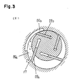
- FIG. 1 is a cylinder; 12, a low pressure side vane chamber; 13, a high pressure side vane chamber; 14, a vane; 15, a slide groove of the vane; 16, a rotor; 17, a suction port; 18, a suction groove; 19, a pressure recovery portion intercepting a section of the suction stream passage; 20, a discharging hole; and 21, a side plate.
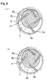
- travelling angle (8) of the vane tip pressure recovery beginning angle ( ⁇ s1 ), and suction finishing angle ( ⁇ s2 ) are defined as follows:
- the vane chamber 26a is an upstream side vane chamber and the vane chamber 26b is a downstream side vane chamber relative to the vane chamber 26a.
- a practical example of a compressor in accordance with an embodiment of the pressnt invention can be constructed using the following parameter values (Table 1).
- a compressor in accordance with this embodiment of the present invention has the following features: (i) At low rates of rotation reduction in refrigerative performance due to suction loss was small.
- a compressor with ability to control refrigerative performance can be realized without sacrificing any of the features of the rotary type compressor e.g. small size, light weight and simple construction.
- the total weight of refrigerant in the vane chamber is smaller and the compressing work is smaller as the suction pressure is lower and the specific weight is smaller. Accordingly, in this compressor in which a dropping of the total weight of refrigerant occurs automatically before the compression phase as rate of rotation increases, dropping of driving torque occurs naturally at high rates of rotation.
- compressor of the present invention refrigerative performance control can be performed without the need for utilising extra mechanics such as valves which cause compression loss.
- An energy-saving refrigerative cycle of high efficiency can be realized.
- the transitional phenomenon of the vane chamber pressure is utilized effectively by proper combination of each parameter of the compressor, and there is no operating part such as a control valve, the compressor of the present invention is highly reliable.
- the first term on the left side shows heat energy of refrigerant to be brought into the vane chamber during unit time passed through the suction port
- the second term shows work to be done by the pressure of refrigerant against the exterior during unit time
- the third term shows heat energy flowing into the vane chamber from exterior through the outer wall during unit time
- the right side shows increase in interior energy within system during unit time.
- equation (1) becomes the following equation from the relationship And, using relation of On the other hand, since the theory of a nozzle can apply to flow quantity (by weight) of refrigerant which passes through the suction port, Accordingly, by solving equations (3) and (4) as simultaneous equations, the transitional character of the vane chamber pressure (Pa) can be obtained. But, said volume of vane chamber Va( ⁇ ) is obtained by following equation.
- Figure 4(b) shows the practical volume of the vane chamber seen from the suction port 17 in the compressor constituted as Figure 2 showing one embodiment of the present invention.
- Figure 5 shows suction effective area between one vane chamber and supply source of refrigerant at the suction stroke.
- suction effective area (a) is decided only by a 1 lies in the fact that the suction groove 18 and suction port 17 have been formed so as to become a 1 «a 2 always in this embodiment.
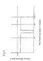
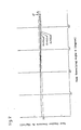
- Figure 7 is a diagram in which the pressure dropping rate relative to rate of rotation was obtained using parameters of the effective area (a 1 ) of the suction stream passage.
- the result as shown in Figure 7 is in no way inferior to the characteristic of the two vane compressor shown as an example in the invention of Patent Application No. 1980-134,048.
- the present method is extremely useful when refrigerative performance control is performed in a compressor with many vanes.
- Figure 9 is a diagram in which the pressure dropping rate relatime to rate of rotation was obtained for a number of different intercepting angles ( ⁇ ) of the suction groove. As ⁇ is smaller, the pressure dropping rate ( ⁇ p) becomes larger and a dropping in volume efficiency occurs.
- an unbroken interception section has been provided at the pressure recovery portion 19, but objects of the present invention can be attained by forming sufficiently shallow grooves along said pressure recovery portion 19.
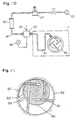
- Figure 10 shows one example of the experimental method, and in the Figure, 100 is a compressed, 101 is a pipe to connect evaporator and suction port of the compressor, as the compressor would be connected on a vehicle, 102 is a pipe for supply of high pressure air, 103 is a housing to connect the pipes 101 and 102, 104 is a thermocouple, 105 is a flow meter, 106 is a pressure gauge, 107 is a pressure regulating valve, and 108 is a high pressure air source.
- 101 is a pipe to connect evaporator and suction port of the compressor, as the compressor would be connected on a vehicle
- 102 is a pipe for supply of high pressure air
- 103 is a housing to connect the pipes 101 and 102
- 104 is a thermocouple
- 105 is a flow meter
- 106 is a pressure gauge
- 107 is a pressure regulating valve
- 108 is a high pressure air source.
- suction effective area (a) is obtained from following formula: But, the pressure of high pressure air source (P 1 ) is set so as to be within the range of 0.528 ⁇ P 1 ⁇ P 2 ⁇ 0.9.
- Figure 11 shows another embodiment of the present invention, and in the Figure, 200 is a rotor, 201, a vane, 202, a cylinder, 203, a suction groove formed in side plate, 204, a suction port formed also on side plate, and 205 is a pressure recovery portion.
- both suction groove and suction port are formed in the cylinder, though those may be formed in side plate as in Figure 11.
- the compressor may have unevenly arranged vanes instead of being arranged with equal angles between them.
Landscapes
- Engineering & Computer Science (AREA)
- Mechanical Engineering (AREA)
- General Engineering & Computer Science (AREA)
- Rotary Pumps (AREA)
Claims (2)
Applications Claiming Priority (2)
| Application Number | Priority Date | Filing Date | Title |
|---|---|---|---|
| JP56173497A JPS5874891A (ja) | 1981-10-28 | 1981-10-28 | ベ−ン形圧縮機 |
| JP173497/81 | 1981-10-28 |
Publications (4)
| Publication Number | Publication Date |
|---|---|
| EP0091968A1 EP0091968A1 (de) | 1983-10-26 |
| EP0091968A4 EP0091968A4 (de) | 1984-04-06 |
| EP0091968B1 true EP0091968B1 (de) | 1988-01-07 |
| EP0091968B2 EP0091968B2 (de) | 1992-03-18 |
Family
ID=15961605
Family Applications (1)
| Application Number | Title | Priority Date | Filing Date |
|---|---|---|---|
| EP82903185A Expired EP0091968B2 (de) | 1981-10-28 | 1982-10-27 | Verdichter |
Country Status (5)
| Country | Link |
|---|---|
| US (1) | US4509905A (de) |
| EP (1) | EP0091968B2 (de) |
| JP (1) | JPS5874891A (de) |
| DE (1) | DE3277926D1 (de) |
| WO (1) | WO1983001659A1 (de) |
Families Citing this family (3)
| Publication number | Priority date | Publication date | Assignee | Title |
|---|---|---|---|---|
| AU1860697A (en) * | 1995-09-08 | 1997-07-28 | Visionary Medical Products Corporation | Pen-type injector drive mechanism |
| CN101127465B (zh) * | 2007-07-26 | 2010-12-01 | 严密 | 磁悬浮飞轮储能系统 |
| US8156919B2 (en) * | 2008-12-23 | 2012-04-17 | Darrow David S | Rotary vane engines with movable rotors, and engine systems comprising same |
Family Cites Families (11)
| Publication number | Priority date | Publication date | Assignee | Title |
|---|---|---|---|---|
| US2361855A (en) * | 1941-05-28 | 1944-10-31 | Gen Motors Corp | Refrigerating apparatus |
| FR68339E (fr) * | 1955-11-04 | 1958-04-29 | Pompe rotative à excentrique et à palettes autocommandées | |
| JPS567079B2 (de) * | 1973-05-15 | 1981-02-16 | ||
| JPS5720851Y2 (de) * | 1977-01-10 | 1982-05-06 | ||
| JPS567079A (en) * | 1979-06-29 | 1981-01-24 | Toshiba Corp | Electronic time-keeper |
| US4299097A (en) * | 1980-06-16 | 1981-11-10 | The Rovac Corporation | Vane type compressor employing elliptical-circular profile |
| JPS5720851A (en) * | 1980-07-11 | 1982-02-03 | Nec Corp | Data processor |
| JPS5770986A (en) * | 1980-09-25 | 1982-05-01 | Matsushita Electric Ind Co Ltd | Compressor |
| JPS57126592A (en) * | 1981-01-29 | 1982-08-06 | Matsushita Electric Ind Co Ltd | Compressor |
| JPS57176384A (en) * | 1981-04-24 | 1982-10-29 | Matsushita Electric Ind Co Ltd | Compressor |
| EP0099412B1 (de) * | 1981-11-11 | 1987-06-03 | Matsushita Electric Industrial Co., Ltd. | Verdichter |
-
1981
- 1981-10-28 JP JP56173497A patent/JPS5874891A/ja active Granted
-
1982
- 1982-10-27 EP EP82903185A patent/EP0091968B2/de not_active Expired
- 1982-10-27 DE DE8282903185T patent/DE3277926D1/de not_active Expired
- 1982-10-27 US US06/516,606 patent/US4509905A/en not_active Expired - Lifetime
- 1982-10-27 WO PCT/JP1982/000420 patent/WO1983001659A1/ja not_active Ceased
Also Published As
| Publication number | Publication date |
|---|---|
| EP0091968A1 (de) | 1983-10-26 |
| EP0091968B2 (de) | 1992-03-18 |
| WO1983001659A1 (fr) | 1983-05-11 |
| JPS5874891A (ja) | 1983-05-06 |
| JPS6157954B2 (de) | 1986-12-09 |
| DE3277926D1 (en) | 1988-02-11 |
| US4509905A (en) | 1985-04-09 |
| EP0091968A4 (de) | 1984-04-06 |
Similar Documents
| Publication | Publication Date | Title |
|---|---|---|
| EP0059834B1 (de) | Verdichter mit Kühlleistungsregelung | |
| EP0049030B1 (de) | Drehkolben-Gleitflügelverdichter | |
| US4619595A (en) | Capacity control device for compressor | |
| EP0091968B1 (de) | Verdichter | |
| JPS60192892A (ja) | ベ−ン型圧縮機 | |
| EP0099412B1 (de) | Verdichter | |
| US3877853A (en) | Vane controlling system for rotary sliding vane compressor | |
| EP0064356B1 (de) | Kompressor | |
| EP0101745B1 (de) | Rotierender verdichter | |
| CN116608129A (zh) | 一种单螺杆压缩机啮合副的喷气结构 | |
| US4708598A (en) | Rotary type gas compressor | |
| US4702684A (en) | Slide vane type compressor with increased suction part-cross-sectional area | |
| CN110762014B (zh) | 上油组件及卧式压缩机 | |
| US4413963A (en) | Self-controllable capacity compressor | |
| JPS6137472B2 (de) | ||
| JPS5882089A (ja) | ベ−ン形圧縮機 | |
| JPS6330516B2 (de) | ||
| JPH0117672Y2 (de) | ||
| JPS58110891A (ja) | ベ−ン圧縮機 | |
| JPH024794B2 (de) | ||
| SENOO et al. | A study of a wet vacuum pump | |
| JPS5920595A (ja) | コンプレツサ | |
| JPS58158390A (ja) | 圧縮機 | |
| JPS58162788A (ja) | 圧縮機 | |
| JPS58140497A (ja) | 回転圧縮機 |
Legal Events
| Date | Code | Title | Description |
|---|---|---|---|
| PUAI | Public reference made under article 153(3) epc to a published international application that has entered the european phase |
Free format text: ORIGINAL CODE: 0009012 |
|
| 17P | Request for examination filed |
Effective date: 19830629 |
|
| AK | Designated contracting states |
Designated state(s): DE GB |
|
| GRAA | (expected) grant |
Free format text: ORIGINAL CODE: 0009210 |
|
| AK | Designated contracting states |
Kind code of ref document: B1 Designated state(s): DE GB |
|
| REF | Corresponds to: |
Ref document number: 3277926 Country of ref document: DE Date of ref document: 19880211 |
|
| PLBI | Opposition filed |
Free format text: ORIGINAL CODE: 0009260 |
|
| 26 | Opposition filed |
Opponent name: LEYBOLD AG Effective date: 19881006 |
|
| PUAH | Patent maintained in amended form |
Free format text: ORIGINAL CODE: 0009272 |
|
| STAA | Information on the status of an ep patent application or granted ep patent |
Free format text: STATUS: PATENT MAINTAINED AS AMENDED |
|
| 27A | Patent maintained in amended form |
Effective date: 19920318 |
|
| AK | Designated contracting states |
Kind code of ref document: B2 Designated state(s): DE GB |
|
| PGFP | Annual fee paid to national office [announced via postgrant information from national office to epo] |
Ref country code: GB Payment date: 19981030 Year of fee payment: 17 |
|
| PGFP | Annual fee paid to national office [announced via postgrant information from national office to epo] |
Ref country code: DE Payment date: 19981103 Year of fee payment: 17 |
|
| PG25 | Lapsed in a contracting state [announced via postgrant information from national office to epo] |
Ref country code: GB Free format text: LAPSE BECAUSE OF NON-PAYMENT OF DUE FEES Effective date: 19991027 |
|
| GBPC | Gb: european patent ceased through non-payment of renewal fee |
Effective date: 19991027 |
|
| PG25 | Lapsed in a contracting state [announced via postgrant information from national office to epo] |
Ref country code: DE Free format text: LAPSE BECAUSE OF NON-PAYMENT OF DUE FEES Effective date: 20000801 |