EP0091834B1 - Verfahren und Vorrichtung zum Entgraten - Google Patents
Verfahren und Vorrichtung zum Entgraten Download PDFInfo
- Publication number
- EP0091834B1 EP0091834B1 EP83302088A EP83302088A EP0091834B1 EP 0091834 B1 EP0091834 B1 EP 0091834B1 EP 83302088 A EP83302088 A EP 83302088A EP 83302088 A EP83302088 A EP 83302088A EP 0091834 B1 EP0091834 B1 EP 0091834B1
- Authority
- EP
- European Patent Office
- Prior art keywords
- weld
- article
- scarfing
- fluid pressure
- sensing means
- Prior art date
- Legal status (The legal status is an assumption and is not a legal conclusion. Google has not performed a legal analysis and makes no representation as to the accuracy of the status listed.)
- Expired
Links
Images
Classifications
-
- B—PERFORMING OPERATIONS; TRANSPORTING
- B23—MACHINE TOOLS; METAL-WORKING NOT OTHERWISE PROVIDED FOR
- B23D—PLANING; SLOTTING; SHEARING; BROACHING; SAWING; FILING; SCRAPING; LIKE OPERATIONS FOR WORKING METAL BY REMOVING MATERIAL, NOT OTHERWISE PROVIDED FOR
- B23D79/00—Methods, machines, or devices not covered elsewhere, for working metal by removal of material
- B23D79/02—Machines or devices for scraping
- B23D79/021—Machines or devices for scraping for removing welding, brazing or soldering burrs, e.g. flash, on pipes or rods
-
- B—PERFORMING OPERATIONS; TRANSPORTING
- B23—MACHINE TOOLS; METAL-WORKING NOT OTHERWISE PROVIDED FOR
- B23K—SOLDERING OR UNSOLDERING; WELDING; CLADDING OR PLATING BY SOLDERING OR WELDING; CUTTING BY APPLYING HEAT LOCALLY, e.g. FLAME CUTTING; WORKING BY LASER BEAM
- B23K37/00—Auxiliary devices or processes, not specially adapted for a procedure covered by only one of the other main groups of this subclass
-
- B—PERFORMING OPERATIONS; TRANSPORTING
- B23—MACHINE TOOLS; METAL-WORKING NOT OTHERWISE PROVIDED FOR
- B23K—SOLDERING OR UNSOLDERING; WELDING; CLADDING OR PLATING BY SOLDERING OR WELDING; CUTTING BY APPLYING HEAT LOCALLY, e.g. FLAME CUTTING; WORKING BY LASER BEAM
- B23K7/00—Cutting, scarfing, or desurfacing by applying flames
- B23K7/06—Machines, apparatus, or equipment specially designed for scarfing or desurfacing
Definitions
- weld material In the longitudinal joining of two members by welding, ortwo longitudinal edges of one member as in the manufacture of tubing, an excess of weld material is usually deposited at the weld.
- Such elongated welds are produced, for example, in the joining of fins to tubes for incorporation into heat transfer devices, like the walls of boilers.
- two fins are welded to each tube, with a weld placed on each side of the fin, at the juncture of each fin with the tube. Since four welds are used on each tube and since the tubes are many metres long, a considerable amount of excess weld is deposited.
- the present invention seeks to provide a scarfing process which is continuous and fast and which can remove excess weld precisely, and to provide apparatus therefor.
- the article bearing the elongate weld is moved relative to a scarfing element which engages the weld to remove excess material therefrom,'and the lateral position of the scarfing- element with respect to the article is controlled by a sensing mechanism and a fluid cylinder operable in response thereto.
- the sensing mechanism comprises a roller which engages the article and a member connected thereto which operates a control valve forthe cylinder.
- the available movement of the sensing mechanism and the scarfing element is normally confined to parallel areas generally perpendicular to the direction of the relative movement between the scarfing element and article as the scarfing proceeds.
- the invention enables changes in the position of the welds to be sensed and the scarfing apparatus to be adjusted accordingly.
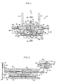
- the scarfing apparatus illustrated in Figure 1 is designated generally by the reference numeral 10, and includes a vertically oriented mounting plate 12 which is stabilized by a pair of stabilizing panels 14 past which is moved the article to be scarfed, which in Figure 1, is shown to be a boiler tube 16 having a fin 18 welded to each of the opposite lateral sides thereof.
- the tube 16 with the fins 18 is drawn from a welding area, in the direction of the arrow A of Figure 1, by any suitable means, such as by pairs of frictionally engaging drive rollers 20 and 21, one roller of each of which is shown in Figure 1.
- the slides 23 and 40 are adjusted so that the cutters 46 and the rollers 62 are at the proper level to engage the tube 16.
- the sensing element support member 51 and the tracer control valve 50 are also adjusted to provide a space of proper width between the rollers 62 to accommodate the tube 16 and fins 18.
- the tube 16 with the fins 18 welded thereto is drawn from a welding area upstream of the scarfing apparatus by the drive rollers 20 and 21 into engagement with rollers 62 and the cutters 46.
- the springs 70 bias the rollers 62 into engagement with the free edges of the fins 18, and the springs 92 bias the operating stems 68 of the tracer control valves 50 into engagement with the tail members 61.
Landscapes
- Physics & Mathematics (AREA)
- Optics & Photonics (AREA)
- Engineering & Computer Science (AREA)
- Mechanical Engineering (AREA)
- Machine Tool Copy Controls (AREA)
- Milling, Broaching, Filing, Reaming, And Others (AREA)
- Veneer Processing And Manufacture Of Plywood (AREA)
Claims (9)
Applications Claiming Priority (2)
| Application Number | Priority Date | Filing Date | Title |
|---|---|---|---|
| US36805982A | 1982-04-13 | 1982-04-13 | |
| US368059 | 1982-04-13 |
Publications (2)
| Publication Number | Publication Date |
|---|---|
| EP0091834A1 EP0091834A1 (de) | 1983-10-19 |
| EP0091834B1 true EP0091834B1 (de) | 1986-07-23 |
Family
ID=23449708
Family Applications (1)
| Application Number | Title | Priority Date | Filing Date |
|---|---|---|---|
| EP83302088A Expired EP0091834B1 (de) | 1982-04-13 | 1983-04-13 | Verfahren und Vorrichtung zum Entgraten |
Country Status (4)
| Country | Link |
|---|---|
| EP (1) | EP0091834B1 (de) |
| JP (2) | JPS58186512A (de) |
| CA (1) | CA1214929A (de) |
| ES (1) | ES521403A0 (de) |
Families Citing this family (2)
| Publication number | Priority date | Publication date | Assignee | Title |
|---|---|---|---|---|
| CN103543784B (zh) * | 2013-11-12 | 2016-04-06 | 上海嘉耐真空设备有限公司 | 单臂式可控限位气缸固定机构 |
| CN112207366B (zh) * | 2020-10-26 | 2021-08-10 | 山东辰之翼信息科技有限公司 | 一种用于高端装备制造的金属原材料切割加工装置 |
Citations (1)
| Publication number | Priority date | Publication date | Assignee | Title |
|---|---|---|---|---|
| US2009670A (en) * | 1930-08-18 | 1935-07-30 | Henry E Morton | Flash removing machine |
Family Cites Families (9)
| Publication number | Priority date | Publication date | Assignee | Title |
|---|---|---|---|---|
| DE907285C (de) * | 1951-02-21 | 1954-03-22 | Hugo Miebach G M B H | Entgratvorrichtung an elektrischen Band-Stumpfschweissmaschinen mit pflugartigen Schermessern |
| US3269248A (en) * | 1963-09-27 | 1966-08-30 | All State Welding Alloys Co In | Apparatus for processing welding wire |
| DE1527653C3 (de) * | 1966-09-16 | 1975-02-27 | Ischorskij Sawod Imeni A.A. Sdanowa, Kolpino (Sowjetunion) | Anlage zum kontinuierlichen Reinigen der Außenfläche von rundem Walzgut von Zunder und Rost |
| US3597958A (en) * | 1969-02-04 | 1971-08-10 | Rock Mill Inc | Machine for removing the bead from the joint of a welded railway rail |
| JPS567402Y2 (de) * | 1974-06-17 | 1981-02-18 | ||
| DE2511004C2 (de) * | 1975-03-13 | 1977-03-24 | Kieserling & Albrecht | Verfahren und einrichtung zum thermischen abtragen von oberflaechenverunreinigungen an insbesondere warmgewalztem stranggut mit kreisfoermigem oder annaehernd kreisfoermigem querschnitt |
| JPS53112593A (en) * | 1977-03-14 | 1978-10-02 | Nippon Steel Corp | Method for removing welding fins of steel band |
| JPS5757870Y2 (de) * | 1977-08-24 | 1982-12-11 | ||
| JPS5511759A (en) * | 1978-07-10 | 1980-01-26 | Sumitomo Metal Ind Ltd | Trimming method of strip welding |
-
1983
- 1983-03-09 CA CA000423198A patent/CA1214929A/en not_active Expired
- 1983-04-07 JP JP6008483A patent/JPS58186512A/ja active Pending
- 1983-04-12 ES ES521403A patent/ES521403A0/es active Granted
- 1983-04-13 EP EP83302088A patent/EP0091834B1/de not_active Expired
-
1986
- 1986-06-13 JP JP1986089407U patent/JPH035377Y2/ja not_active Expired
Patent Citations (1)
| Publication number | Priority date | Publication date | Assignee | Title |
|---|---|---|---|---|
| US2009670A (en) * | 1930-08-18 | 1935-07-30 | Henry E Morton | Flash removing machine |
Also Published As
| Publication number | Publication date |
|---|---|
| CA1214929A (en) | 1986-12-09 |
| JPH035377Y2 (de) | 1991-02-12 |
| ES8403765A1 (es) | 1984-04-01 |
| EP0091834A1 (de) | 1983-10-19 |
| JPS61205721U (de) | 1986-12-25 |
| JPS58186512A (ja) | 1983-10-31 |
| ES521403A0 (es) | 1984-04-01 |
Similar Documents
| Publication | Publication Date | Title |
|---|---|---|
| CA1112555A (en) | Cutting of contour bevels | |
| SE463701B (sv) | Saett att utfoera en v-formad bockning i en press och anordning foer justering av ett stoedelement i en press | |
| US4478120A (en) | Metal-sawing machine | |
| US4587698A (en) | Scarfing method and apparatus | |
| EP0091834B1 (de) | Verfahren und Vorrichtung zum Entgraten | |
| US4543022A (en) | Self-positioning scarfing apparatus | |
| CA1172955A (en) | Zone heating and shearing system, and method | |
| CA1037505A (en) | Stop mechanism for a bending press, plate shear or the like machines | |
| JP6153548B2 (ja) | 管等の形材の内側の溶接ビードの除去のための切り込み深さの調整装置 | |
| US4255999A (en) | Method and apparatus for removing camber from strip | |
| US3257906A (en) | Edge trimming machine | |
| US2758515A (en) | Template system for contour milling machines | |
| US3762249A (en) | Shearing apparatus | |
| US3706246A (en) | Process for slitting sheet metal | |
| US3713357A (en) | Apparatus for slitting sheet metal | |
| WO1992015410A1 (fr) | Dispositif de compensation automatique de l'angle de pliage dans un frein de presse | |
| US3803961A (en) | Apparatus for fabricating elongated structural members, or the like | |
| US2412957A (en) | Machine tool control | |
| US2970206A (en) | Metal joiner, particularly for strip | |
| US3331286A (en) | Tool for removing inside flash from welded pipe | |
| US3997094A (en) | Device for aligning power press feedstock | |
| GB2098524A (en) | Burr removing | |
| JPS56114618A (en) | Method of removing surface flaw from wire rod | |
| JP3394656B2 (ja) | 電縫鋼管の外面ビード切削装置 | |
| US4318320A (en) | Method for removing camber from strip |
Legal Events
| Date | Code | Title | Description |
|---|---|---|---|
| PUAI | Public reference made under article 153(3) epc to a published international application that has entered the european phase |
Free format text: ORIGINAL CODE: 0009012 |
|
| AK | Designated contracting states |
Designated state(s): FR GB IT |
|
| 17P | Request for examination filed |
Effective date: 19840321 |
|
| GRAA | (expected) grant |
Free format text: ORIGINAL CODE: 0009210 |
|
| AK | Designated contracting states |
Kind code of ref document: B1 Designated state(s): FR GB IT |
|
| ITF | It: translation for a ep patent filed | ||
| ET | Fr: translation filed | ||
| PLBE | No opposition filed within time limit |
Free format text: ORIGINAL CODE: 0009261 |
|
| STAA | Information on the status of an ep patent application or granted ep patent |
Free format text: STATUS: NO OPPOSITION FILED WITHIN TIME LIMIT |
|
| 26N | No opposition filed | ||
| PG25 | Lapsed in a contracting state [announced via postgrant information from national office to epo] |
Ref country code: FR Free format text: LAPSE BECAUSE OF NON-PAYMENT OF DUE FEES Effective date: 19891228 |
|
| REG | Reference to a national code |
Ref country code: FR Ref legal event code: ST |
|
| PGFP | Annual fee paid to national office [announced via postgrant information from national office to epo] |
Ref country code: GB Payment date: 19900402 Year of fee payment: 8 |
|
| PG25 | Lapsed in a contracting state [announced via postgrant information from national office to epo] |
Ref country code: GB Effective date: 19910413 |
|
| GBPC | Gb: european patent ceased through non-payment of renewal fee |