EP0091569B1 - Leistungsregler für eine hydrostatische Pumpe - Google Patents
Leistungsregler für eine hydrostatische Pumpe Download PDFInfo
- Publication number
- EP0091569B1 EP0091569B1 EP83102579A EP83102579A EP0091569B1 EP 0091569 B1 EP0091569 B1 EP 0091569B1 EP 83102579 A EP83102579 A EP 83102579A EP 83102579 A EP83102579 A EP 83102579A EP 0091569 B1 EP0091569 B1 EP 0091569B1
- Authority
- EP
- European Patent Office
- Prior art keywords
- pressure
- piston
- pump
- line
- controller according
- Prior art date
- Legal status (The legal status is an assumption and is not a legal conclusion. Google has not performed a legal analysis and makes no representation as to the accuracy of the status listed.)
- Expired
Links
- 230000002706 hydrostatic effect Effects 0.000 title claims 2
- 230000007935 neutral effect Effects 0.000 description 3
- 238000010586 diagram Methods 0.000 description 2
- 230000006835 compression Effects 0.000 description 1
- 238000007906 compression Methods 0.000 description 1
- 238000006073 displacement reaction Methods 0.000 description 1
- 238000004519 manufacturing process Methods 0.000 description 1
- 230000000630 rising effect Effects 0.000 description 1
Images

Classifications
-
- F—MECHANICAL ENGINEERING; LIGHTING; HEATING; WEAPONS; BLASTING
- F04—POSITIVE - DISPLACEMENT MACHINES FOR LIQUIDS; PUMPS FOR LIQUIDS OR ELASTIC FLUIDS
- F04B—POSITIVE-DISPLACEMENT MACHINES FOR LIQUIDS; PUMPS
- F04B49/00—Control, e.g. of pump delivery, or pump pressure of, or safety measures for, machines, pumps, or pumping installations, not otherwise provided for, or of interest apart from, groups F04B1/00 - F04B47/00
- F04B49/002—Hydraulic systems to change the pump delivery
-
- F—MECHANICAL ENGINEERING; LIGHTING; HEATING; WEAPONS; BLASTING
- F04—POSITIVE - DISPLACEMENT MACHINES FOR LIQUIDS; PUMPS FOR LIQUIDS OR ELASTIC FLUIDS
- F04B—POSITIVE-DISPLACEMENT MACHINES FOR LIQUIDS; PUMPS
- F04B2201/00—Pump parameters
- F04B2201/12—Parameters of driving or driven means
- F04B2201/1203—Power on the axis
Definitions
- the invention is based on a power controller according to the preamble of the main claim. Such is described in the unpublished DE-A-3 200 885. With such a known power regulator, it is possible to place the operating points approximately on a hyperbola in a PQ diagram. However, such a device has the disadvantage that points below the power hyperbola can only be controlled by means of auxiliary pressure, which can possibly lead to accidents, or that a lossy throttle must be arranged in the main flow.
- the power controller according to the invention with the characterizing features of the main claim has the advantage that the pump can be reset via falling instead of rising control pressure. Points below the performance hyper can be targeted. By such a device, the risk of accidents z. B. eliminated if the control pressure fails. In addition, losses due to a throttle which is often arranged in the main delivery line are avoided.
- FIG. 1 shows a power control device with a variable displacement pump in a schematic illustration
- FIG. 2 shows a second similar exemplary embodiment
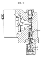
- FIG. 3 shows a detail.
- 10 denotes a radial piston pump, the stroke ring 11 of which is adjusted with the aid of two counteracting adjusting pistons 12, 13.
- the actuating piston 12 has a much larger diameter than the actuating piston 13.
- the radial piston pump 10 draws in pressure medium via a line 14 from a container 15 and conveys it into a delivery line 16.
- a line 18 branches off from the delivery line 16 and leads to the pressure chamber 21 leads the actuating piston 13 receiving bore 20.
- a line 22 continues from the delivery line 16, which leads to a control valve 23 which is designed as a 3/3-way valve with the switching positions I, II and 111.
- a line 25 extends from the control valve 23 and opens into the first pressure chamber 26 of a housing 27 into which a volumetric piston 28 is immersed.
- the piston part 30 has a much larger diameter than the plunger 29.
- a pressure spring 32 acts on the piston part 30 and lies in the rear part of the bore 31 facing away from the plunger 29.
- a line 35 opens, which starts from a line 37 connected to an auxiliary pump 36; the auxiliary pump sucks pressure medium from the container 15.
- a preferably adjustable pressure relief valve 38 is arranged at the end of line 37, and a throttle 39 in line 37 behind the pump.
- a line 40 leads from the control valve 23 to a pressure chamber 41 of a bore 42 which receives the actuating piston 12. Furthermore, a line 43 leads from the control valve 23 to the container 15.
- Two pressure springs 45, 46 act on the control valve 23, which are shown symbolically in FIG. 1, but can be seen more clearly in FIG. 3. They act on the control slide 23 'of the control valve 23, one after the other.
- the two springs 45, 46 are supported on a spring plate 47, which is fastened to a guide rod 48, which supports itself again on the bottom of the actuating piston 12.
- the control slide 23 ' is always in contact with the spring 45, but only after a certain adjustment path on the spring 46. These therefore come into engagement one after the other, which approximately results in a hyperbolic characteristic curve over pressure and volume. Such arrangements are known per se.
- the tracking rod 48 penetrates through the hollow interior of the control slide 23 '.
- an extension 50 On the control valve 23 and facing away from the pump there is an extension 50 on which the arm 51 of an angle lever 53 which is pivotable about a pivot point 52 fixed to the housing is articulated.
- the volumetric flask 28 bears against its end 53 '.
- the angle lever 53 has an extension 55 which interacts with a stop 56.
- a similar stop 57 is located at the opposite end of the angle lever.
- the control device works as follows: It is assumed that the larger-area actuating piston 12 has raised the stroke ring 11 of the pump and has displaced pressure medium into the delivery line 16. The pressure prevailing in the delivery line propagates via line 18 into pressure chamber 21 on actuating piston 13, as well as via lines 22 and 25 to pressure chamber 26 on volumetric piston 28. It should also be assumed that auxiliary pump 36 delivers fully, as a result of which the differential piston 30 is pressed against the force of the spring 32 to the left and the plunger 29 now does not touch the volumetric piston 28. If the pressure in the delivery line 16 has reached a certain limit value, the angle lever 53 is pivoted about the fulcrum 52 by the force of the measuring piston 28 and brings the control valve 23 from its previous neutral position 11 to the position 111.
- the setpoint pressure generated in the line 37 of the auxiliary pump 36 depends on the cut-off pressure of the pressure relief valve 38. If this control pressure is reduced compared to the normal value now present, e.g. by reducing the cut-off pressure at the pressure valve 38, then the pressure in the pressure chamber 33 drops.
- the spring 32 now presses the differential piston and thus its plunger 29 against the measuring piston 28 and simulates a working pressure on the latter which is greater than that currently prevailing in the delivery line 16 .
- the angle lever 53 is pivoted and the directional control valve 23 is set, as described above, in such a way that the pump 10 is set to a smaller delivery rate. From this it can be seen that in the event of a failure or an arbitrary reduction in the control pressure in line 37, the pump 10 is reset via falling instead of increasing control pressure. This can eliminate any possible risk of an accident.
- the setting of the pump 10 again follows the above-mentioned performance hyperbole. This ensures that the pump 10 always adjusts to the smaller of the two setpoints from the working pressure in the delivery line 16 or the control pressure in line 35. If the control pressure is reduced to a very low value or to zero, the force of the spring 32 on the differential piston and thus on the measuring piston 28 becomes so great that the pump is reset to zero.
- the exemplary embodiment according to FIG. 2 differs from the previous one in that a line 60 branches off from the line 25 and leads to the end face of a 3/2-way valve 61 which is loaded against this pressure force by a spring 62.
- the directional control valve 61 is switched on in line 37.
- control pressure prevailing in line 37 can be influenced by the operating pressure prevailing in delivery line 16. If the latter has reached a certain size, the directional control valve 62 is switched from its flow position I to the position II, as a result of which pressure medium flows directly out of the line 37 to the container 15. As a result, the pressure in the pressure chamber 33 drops very quickly, so that the pump 10 is immediately reset (pressure cutoff).
- the differential piston is also divided into a separate piston 30 'and a plunger 29' for manufacturing reasons.
- the function remains the same as before.
Landscapes
- Engineering & Computer Science (AREA)
- Mechanical Engineering (AREA)
- General Engineering & Computer Science (AREA)
- Reciprocating Pumps (AREA)
- Control Of Positive-Displacement Pumps (AREA)
Description
- Die Erfindung geht aus von einem Leistungsregler nach der Gattung des Hauptanspruchs. Ein solcher ist in der nicht vorveröffentlichten DE-A-3 200 885 beschrieben. Mit einem derartigen bekannten Leistungsregler ist es möglich, die Arbeitspunkte angenähert auf eine Hyperbel in einem PQ-Diagramm zu legen. Eine derartige Einrichtung hat jedoch den Nachteil, dass Punkte unterhalb der Leistungshyperbel nur mittels Hilfsdruck angesteuert werden können, was unter Umständen zu Unfällen führen kann, oder dass im Hauptstrom eine verlustbehaftete Drossel angeordnet werden muss.
- Der erfindungsgemässe Leistungsregler mit den kennzeichnenden Merkmalen des Hauptanspruchs hat demgegenüber den Vorteil, dass das Zurückstellen der Pumpe über fallenden anstatt über steigenden Steuerdruck möglich ist. Es können gezielt Punkte unterhalb der Leistungshyperbei angefahren werden. Durch eine derartige Einrichtung wird die Unfallgefahr z. B. bei Ausfallen des Steuerdrucks beseitigt. Im übrigen werden Verluste durch eine häufig in der Haupt-Förderleitung angeordnete Drossel vermieden.
- Durch die in den Unteransprüchen aufgeführten Massnahmen sind Weiterbildungen der im Hauptanspruch angegebenen Merkmale möglich.
- Zwei Ausführungsbeispiele der Erfindung sind in der Zeichnung dargestellt und in der nachfolgenden Beschreibung näher erläutert. Es zeigen Figur 1 eine Leistungsregeleinrichtung mit Verstellpumpe in schematischer Darstellung, Figur 2 ein zweites ähnliches Ausführungsbeispiel, Figur 3 eine Einzelheit.
- In Figur 1 ist mit 10 eine Radialkolbenpumpe bezeichnet, deren Hubring 11 mit Hilfe zweier einander entgegenwirkender Stellkolben 12, 13 eingestellt wird. Der Stellkolben 12 hat einen wesentlich grösseren Durchmesser als der Stellkolben 13. Die Radialkolbenpumpe 10 saugt Druckmittel über eine Leitung 14 aus einem Behälter 15 an und fördert dieses in eine Förderleitung 16. Von der Förderleitung 16 zweigt eine Leitung 18 ab, welche zum Druckraum 21 einer den Stellkolben 13 aufnehmenden Bohrung 20 führt. Von der Förderleitung 16 geht weiterhin eine Leitung 22 aus, die an ein Steuerventil 23 führt, das als 3/3-Wegeventil mit den Schaltstellungen, I, II und 111 ausgebildet ist. Vom Steuerventil 23 geht eine Leitung 25 aus, die im ersten Druckraum 26 eines Gehäuses 27 mündet, in den ein Messkolben 28 eintaucht. Weiterhin taucht in den Druckraum 26 der Stössel 29 eines Differentialkolbens 30 ein, der in einer Bohrung 31 des Gehäuses 27 geführt ist. Der Kolbenteil 30 hat einen wesentlich grösseren Durchmesser als der Stössel 29. Auf den Kolbenteil 30 wirkt eine Druckfeder 32 ein, die im hinteren, dem Stössel 29 abgewandten Teil der Bohrung 31 liegt. In den vorderen Teil der Bohrung 31, der als Druckraum 33 bezeichnet ist, mündet eine Leitung 35, die von einer an eine Hilfspumpe 36 angeschlossenen Leitung 37 ausgeht; die Hilfspumpe saugt Druckmittel aus dem Behälter 15 an. Am Ende der Leitung 37 ist ein vorzugsweise verstellbares Druckbegrenzungsventil 38 angeordnet, in der Leitung 37 hinter der Pumpe eine Drossel 39.
- Vom Steuerventil 23 führt eine Leitung 40 zu einem Druckraum 41 einer Bohrung 42, die den Stellkolben 12 aufnimmt. Weiterhin führt vom Steuerventil 23 eine Leitung 43 zum Behälter 15.
- Auf das Steuerventil 23 wirken zwei Druckfedern 45, 46 ein, die in Figur 1 symbolisch dargestellt, jedoch in Figur 3 deutlicher zu erkennen sind. Sie wirken auf den Steuerschieber 23' des Steuerventils 23 ein, und zwar nacheinander. Die beiden Federn 45, 46 stützen sich an einem Federteller 47 ab, der an einer Nachführstange 48 befestigt ist, die sich selbst wieder am Boden des Stellkolbens 12 abstützt. Der Steuerschieber 23' liegt stets an der Feder 45 an, jedoch erst nach einem bestimmten Verstellweg an der Feder 46. Diese kommen also nacheinander in Eingriff, woraus sich angenähert ein Hyperbelkennlinie über Druck und Volumen ergibt. Derartige Anordnungen sind an sich bekannt. Die Nachführstange 48 dringt durch das hohle Innere des Steuerschiebers 23'.
- Am Steuerventil 23 und der Pumpe abgewandt befindet sich ein Fortsatz 50, an dem der Arm 51 eines um einen gehäusefesten Drehpunkt 52 schwenkbaren Winkelhebels 53 angelenkt ist. An dessen Ende 53' legt sich der Messkolben 28 an. Der Winkelhebel 53 hat eine Verlängerung 55, die mit einem Anschlag 56 zusammenwirkt. Ein ähnlicher Anschlag 57 befindet sich am gegenüberliegenden Ende des Winkelhebels.
- Die Regeleinrichtung arbeitet wie folgt: Es sei angenommen, dass der flächengrössere Stellkolben 12 den Hubring 11 der Pumpe ausgestellt hat und diese in die Förderleitung 16 Druckmittel verdrängt. Der in der Förderleitung herrschende Druck pflanzt sich über die Leitung 18 in den Druckraum 21 am Stellkolben 13 fort, sowie über die Leitungen 22 und 25 zum Druckraum 26 am Messkolben 28. Es sei weiterhin angenommen, dass die Hilfspumpe 36 voll fördere, wodurch der Differentialkolben 30 entgegen der Kraft der Feder 32 nach links gedrückt wird und der Stössel 29 nun den Messkolben 28 nicht berührt. Hat der Druck in der Förderleitung 16 einen bestimmten Grenzwert erreicht, dann wird der Winkelhebel 53 durch die Kraft des Messkolbens 28 um den Drehpunkt 52 verschwenkt und bringt das Steuerventil 23 von seiner vorherigen Neutralstellung 11 in die Stellung 111. Dadurch kann Druckmittel aus dem Druckraum 41 über die Leitungen 40, 43 zum Behälter 15 abströmen. Im Druckraum 21 herrscht nach wie vor der Förderdruck, so dass die Pumpe nun auf kleinere Fördermenge zurückgestellt wird. Dadurch werden die Federn 45 und 46 stärker gespannt, und sie stellen das Steuerventil 23 wieder in seine Neutralstellung II. Der Winkelhebel 53 schiebt dabei den Messkolben 28 in seine vorherige Lage.
- Fällt umgekehrt der Druck, dann bringen die Druckfedern 45 und/oder 46 das Steuerventil 29 in seine Schaltstellung I, so dass nun Druckmittel über die Leitungen 22 und 40 in den Druckraum 41 eindringen kann und die Pumpe 10 wieder auf grössere Fördermenge einstellt. Dadurch sinkt die Kraft der Federn 45 und 46, der Messkolben 28 verschwenkt den Winkelhebel 53, und dieser bringt das Steuerventil 23 wieder in seine Neutralstellung II. Durch die Anordnung der beiden nacheinander in Eingriff kommenden Druckfedern 45, 46 erhält man eine angenäherte Leistungshyperbel in einem PQ-Diagramm.
- Der in der Leitung 37 der Hilfspumpe 36 erzeugte Solldruck hängt ab vom Abschaltdruck des Druckbegrenzungsventils 38. Wird dieser Steuerdruck gegenüber dem jetzt vorliegenden Normalwert reduziert, z.B. durch Verminderung des Abschaltdrucks am Druckventil 38, dann fällt der Druck im Druckraum 33. Die Feder 32 drückt nun den Differentialkolben und damit dessen Stössel 29 gegen den Messkolben 28 und simuliert an diesem einen Arbeitsdruck, der grösser ist als der momentan in der Förderleitung 16 herrschende. Dadurch wird der Winkelhebel 53 verschwenkt, und das Wegeventil 23 wird - wie weiter oben beschrieben - so eingestellt, dass die Pumpe 10 auf kleinere Fördermenge eingestellt wird. Daraus ist zu erkennen, dass bei Ausfall oder willkürlicher Reduzierung des Steuerdrucks in der Leitung 37 das Rückstellen der Pumpe 10 über fallenden statt über steigenden Steuerdruck erfolgt. Hierdurch kann eine eventuell gegebene Unfallgefahr beseitigt werden.
- Ergibt der tatsächlich in der Förderleitung 16 herrschende Arbeitsdruck eine höhere Kraft auf den Messkolben 28 als es durch die Wirkung von Federkraft 32 minus Steuerdruck 35 entspricht, folgt die Einstellung der Pumpe 10 wieder der oben genannten Leistungshyperbel. Damit ist sichergestellt, dass sich die Pumpe 10 immer auf den kleineren der beiden Sollwerte aus Arbeitsdruck in der Förderleitung 16 bzw. Steuerdruck in der Leitung 35 einstellt. Wird der Steuerdruck auf einen sehr niedrigen Wert oder auf Null abgesenkt, wird die Kraft der Feder 32 auf den Differentialkolben und damit auf den Messkolben 28 so gross, dass die Pumpe nach Null zurückgestellt wird.
- Das Ausführungsbeispiel nach Figur 2 unterscheidet sich von dem vorhergehenden dadurch, dass nun von der Leitung 25 eine Leitung 60 abzweigt, die an die Stirnseite eines 3/2-Wegeventils 61 führt, das entgegen dieser Druckkraft von einer Feder 62 belastet ist. Das Wegeventil 61 ist in die Leitung 37 eingeschaltet.
- Bei diesem Ausführungsbeispiel kann der in der Leitung 37 herrschende Steuerdruck von dem in der Förderleitung 16 herrschenden Betriebsdruck beeinflusst werden. Hat letzterer eine gewisse Grösse erreicht, so wird das Wegeventil 62 von seiner Durchflussstellung I in die Stellung II geschaltet, wodurch Druckmittel unmittelbar aus der Leitung 37 zum Behälter 15 abströmt. Dadurch sinkt der Druck im Druckraum 33 sehr schnell, so dass die Pumpe 10 sofort zurückgestellt wird (Druckabschneidung).
- In diesem Ausführungsbeispiel ist ausserdem der Differentialkolben aus fertigungstechnischen Gründen in einen getrennten Kolben 30' und einen Stössel 29' aufgeteilt. Die Funktion bleibt dadurch dieselbe wie zuvor.
Claims (5)
Applications Claiming Priority (2)
| Application Number | Priority Date | Filing Date | Title |
|---|---|---|---|
| DE19823213377 DE3213377A1 (de) | 1982-04-10 | 1982-04-10 | Leistungsregler fuer eine hydrostatische pumpe |
| DE3213377 | 1982-04-10 |
Publications (3)
| Publication Number | Publication Date |
|---|---|
| EP0091569A2 EP0091569A2 (de) | 1983-10-19 |
| EP0091569A3 EP0091569A3 (en) | 1985-06-19 |
| EP0091569B1 true EP0091569B1 (de) | 1987-07-15 |
Family
ID=6160684
Family Applications (1)
| Application Number | Title | Priority Date | Filing Date |
|---|---|---|---|
| EP83102579A Expired EP0091569B1 (de) | 1982-04-10 | 1983-03-16 | Leistungsregler für eine hydrostatische Pumpe |
Country Status (3)
| Country | Link |
|---|---|
| US (1) | US4509902A (de) |
| EP (1) | EP0091569B1 (de) |
| DE (2) | DE3213377A1 (de) |
Families Citing this family (5)
| Publication number | Priority date | Publication date | Assignee | Title |
|---|---|---|---|---|
| DE3340332C2 (de) * | 1983-11-08 | 1988-11-10 | Hydromatik GmbH, 7915 Elchingen | Leistungs-Regelvorrichtung für einen hydrostatischen Antrieb mit Fördermengeneinstellung |
| US4711616A (en) * | 1984-12-13 | 1987-12-08 | Nippondenso Co., Ltd. | Control apparatus for a variable displacement pump |
| GB8802022D0 (en) * | 1988-01-29 | 1988-02-24 | Drum Eng Co Ltd | Improvements in & relating to pump apparatus for discharging liquid |
| ITBO20030528A1 (it) * | 2003-09-12 | 2005-03-13 | Pierburg Spa | Impianto di pompaggio utilizzante una pompa a palette |
| US8123492B2 (en) * | 2004-09-20 | 2012-02-28 | Magna Powertrain Inc. | Speed-related control mechanism for a pump and control method |
Citations (1)
| Publication number | Priority date | Publication date | Assignee | Title |
|---|---|---|---|---|
| DE3200885A1 (de) * | 1982-01-14 | 1983-07-21 | Robert Bosch Gmbh, 7000 Stuttgart | Leistungsregler fuer eine hydrostatische pumpe |
Family Cites Families (6)
| Publication number | Priority date | Publication date | Assignee | Title |
|---|---|---|---|---|
| DE1811383A1 (de) * | 1968-11-28 | 1970-06-18 | Bosch Gmbh Robert | Regel- und Steuereinrichtung fuer eine verstellbare Pumpe |
| DE2356795A1 (de) * | 1973-11-14 | 1975-05-15 | Bosch Gmbh Robert | Steuereinrichtung fuer eine verstellbare pumpe |
| DE2461897A1 (de) * | 1974-12-31 | 1976-07-08 | Bosch Gmbh Robert | Regeleinrichtung fuer eine pumpe |
| DE2505780C2 (de) * | 1975-02-12 | 1986-03-06 | Robert Bosch Gmbh, 7000 Stuttgart | Einrichtung zum Regeln wenigstens einer verstellbaren Pumpe |
| US3969896A (en) * | 1975-05-08 | 1976-07-20 | Sundstrand Corporation | Transmission ratio control system |
| US4013381A (en) * | 1976-02-09 | 1977-03-22 | Caterpillar Tractor Co. | Pump control assembly having adjustable biasing means |
-
1982
- 1982-04-10 DE DE19823213377 patent/DE3213377A1/de not_active Withdrawn
-
1983
- 1983-03-16 EP EP83102579A patent/EP0091569B1/de not_active Expired
- 1983-03-16 DE DE8383102579T patent/DE3372523D1/de not_active Expired
- 1983-04-04 US US06/481,264 patent/US4509902A/en not_active Expired - Fee Related
Patent Citations (1)
| Publication number | Priority date | Publication date | Assignee | Title |
|---|---|---|---|---|
| DE3200885A1 (de) * | 1982-01-14 | 1983-07-21 | Robert Bosch Gmbh, 7000 Stuttgart | Leistungsregler fuer eine hydrostatische pumpe |
Also Published As
| Publication number | Publication date |
|---|---|
| US4509902A (en) | 1985-04-09 |
| DE3213377A1 (de) | 1983-10-13 |
| EP0091569A3 (en) | 1985-06-19 |
| EP0091569A2 (de) | 1983-10-19 |
| DE3372523D1 (en) | 1987-08-20 |
Similar Documents
| Publication | Publication Date | Title |
|---|---|---|
| DE1528550C3 (de) | Hydrostatisches Getriebe mit einer Pumpe und mehreren über je ein Wegventil anschließbaren Hydromotoren sowie einem Servostellgerät | |
| DE3535771C2 (de) | ||
| DE2505780C2 (de) | Einrichtung zum Regeln wenigstens einer verstellbaren Pumpe | |
| DE2603563C2 (de) | Steuereinrichtung für ein aus mindestens zwei Pumpen bestehendes Pumpen-Aggregat | |
| DE10001826C1 (de) | Vorrichtung zum Regeln der Leistung einer verstellbaren Kolbenmaschine | |
| EP0402390B1 (de) | Steuerungsanordnung für eine zweizylinder-dickstoffpumpe | |
| DE1625014A1 (de) | Hydraulisches Kraftuebertragungssystem | |
| EP0091569A2 (de) | Leistungsregler für eine hydrostatische Pumpe | |
| EP1502027B1 (de) | Regeleinrichtung mit grenzwertregelventil | |
| EP0086276B1 (de) | Einrichtung zum Konstanthalten des Produktes von Förderdruck und Fördervolumen einer verstellbaren Pumpe | |
| US3543515A (en) | Hydraulic apparatus | |
| EP0423257B1 (de) | Einrichtung an einer verstellbaren hydrostatischen pumpe | |
| DE1154689B (de) | Einrichtung zum Steuern einer stufenlos regelbaren hydrostatischen Einheit | |
| EP0100784B1 (de) | Druckbegrenzungsventil mit elektrisch einstellbarem Ansprechwert | |
| DE3200885A1 (de) | Leistungsregler fuer eine hydrostatische pumpe | |
| EP0402871A2 (de) | Regeleinrichtung für eine verstellbare Pumpe | |
| DE2349124C2 (de) | Steuervorrichtung für eine im Speicherbetrieb arbeitende hydraulische Verstellpumpe | |
| DE3034115C2 (de) | Leistungsregler | |
| DE1500327B1 (de) | Stellgerät für eine stufenlos einstellbare Pumpe eines hydrostatischen Getriebes | |
| DE1267092B (de) | Leistungsregler fuer Kolbenpumpen und -motoren | |
| DE3501455C2 (de) | Leistungsregler für eine hydrostatische Pumpe | |
| DE2121267A1 (de) | Verstellpumpe mit Verstellvorrichtung | |
| DE2152699C2 (de) | Testgegerät für Hydraulikanlagen | |
| DE2810062A1 (de) | Regeleinrichtung | |
| DE1728016A1 (de) | Hydraulische Verstelleinrichtung zur Verstellung von hydrostatischen Einheiten |
Legal Events
| Date | Code | Title | Description |
|---|---|---|---|
| PUAI | Public reference made under article 153(3) epc to a published international application that has entered the european phase |
Free format text: ORIGINAL CODE: 0009012 |
|
| 17P | Request for examination filed |
Effective date: 19830316 |
|
| AK | Designated contracting states |
Designated state(s): DE FR GB |
|
| PUAL | Search report despatched |
Free format text: ORIGINAL CODE: 0009013 |
|
| AK | Designated contracting states |
Designated state(s): DE FR GB |
|
| RHK1 | Main classification (correction) |
Ipc: F04B 49/08 |
|
| 17Q | First examination report despatched |
Effective date: 19860129 |
|
| GRAA | (expected) grant |
Free format text: ORIGINAL CODE: 0009210 |
|
| AK | Designated contracting states |
Kind code of ref document: B1 Designated state(s): DE FR GB |
|
| REF | Corresponds to: |
Ref document number: 3372523 Country of ref document: DE Date of ref document: 19870820 |
|
| ET | Fr: translation filed | ||
| PLBE | No opposition filed within time limit |
Free format text: ORIGINAL CODE: 0009261 |
|
| STAA | Information on the status of an ep patent application or granted ep patent |
Free format text: STATUS: NO OPPOSITION FILED WITHIN TIME LIMIT |
|
| 26N | No opposition filed | ||
| PGFP | Annual fee paid to national office [announced via postgrant information from national office to epo] |
Ref country code: GB Payment date: 19890331 Year of fee payment: 7 Ref country code: FR Payment date: 19890331 Year of fee payment: 7 |
|
| PGFP | Annual fee paid to national office [announced via postgrant information from national office to epo] |
Ref country code: DE Payment date: 19890529 Year of fee payment: 7 |
|
| PG25 | Lapsed in a contracting state [announced via postgrant information from national office to epo] |
Ref country code: GB Effective date: 19900316 |
|
| GBPC | Gb: european patent ceased through non-payment of renewal fee | ||
| PG25 | Lapsed in a contracting state [announced via postgrant information from national office to epo] |
Ref country code: FR Effective date: 19901130 |
|
| PG25 | Lapsed in a contracting state [announced via postgrant information from national office to epo] |
Ref country code: DE Effective date: 19901201 |
|
| REG | Reference to a national code |
Ref country code: FR Ref legal event code: ST |