EP0091361B1 - System for connecting a longitudinal member such as a purlin with a carrying structure - Google Patents
System for connecting a longitudinal member such as a purlin with a carrying structure Download PDFInfo
- Publication number
- EP0091361B1 EP0091361B1 EP83400653A EP83400653A EP0091361B1 EP 0091361 B1 EP0091361 B1 EP 0091361B1 EP 83400653 A EP83400653 A EP 83400653A EP 83400653 A EP83400653 A EP 83400653A EP 0091361 B1 EP0091361 B1 EP 0091361B1
- Authority
- EP
- European Patent Office
- Prior art keywords
- groove
- extension
- branch
- supporting member
- insert
- Prior art date
- Legal status (The legal status is an assumption and is not a legal conclusion. Google has not performed a legal analysis and makes no representation as to the accuracy of the status listed.)
- Expired
Links
Images


Classifications
-
- E—FIXED CONSTRUCTIONS
- E04—BUILDING
- E04B—GENERAL BUILDING CONSTRUCTIONS; WALLS, e.g. PARTITIONS; ROOFS; FLOORS; CEILINGS; INSULATION OR OTHER PROTECTION OF BUILDINGS
- E04B7/00—Roofs; Roof construction with regard to insulation
- E04B7/02—Roofs; Roof construction with regard to insulation with plane sloping surfaces, e.g. saddle roofs
-
- E—FIXED CONSTRUCTIONS
- E04—BUILDING
- E04D—ROOF COVERINGS; SKY-LIGHTS; GUTTERS; ROOF-WORKING TOOLS
- E04D3/00—Roof covering by making use of flat or curved slabs or stiff sheets
- E04D3/02—Roof covering by making use of flat or curved slabs or stiff sheets of plane slabs, slates, or sheets, or in which the cross-section is unimportant
- E04D3/06—Roof covering by making use of flat or curved slabs or stiff sheets of plane slabs, slates, or sheets, or in which the cross-section is unimportant of glass or other translucent material; Fixing means therefor
- E04D3/08—Roof covering by making use of flat or curved slabs or stiff sheets of plane slabs, slates, or sheets, or in which the cross-section is unimportant of glass or other translucent material; Fixing means therefor with metal glazing bars
- E04D2003/0806—Roof covering by making use of flat or curved slabs or stiff sheets of plane slabs, slates, or sheets, or in which the cross-section is unimportant of glass or other translucent material; Fixing means therefor with metal glazing bars the supporting section of the glazing bar consisting of one single extruded or rolled metal part
-
- E—FIXED CONSTRUCTIONS
- E04—BUILDING
- E04D—ROOF COVERINGS; SKY-LIGHTS; GUTTERS; ROOF-WORKING TOOLS
- E04D3/00—Roof covering by making use of flat or curved slabs or stiff sheets
- E04D3/02—Roof covering by making use of flat or curved slabs or stiff sheets of plane slabs, slates, or sheets, or in which the cross-section is unimportant
- E04D3/06—Roof covering by making use of flat or curved slabs or stiff sheets of plane slabs, slates, or sheets, or in which the cross-section is unimportant of glass or other translucent material; Fixing means therefor
- E04D3/08—Roof covering by making use of flat or curved slabs or stiff sheets of plane slabs, slates, or sheets, or in which the cross-section is unimportant of glass or other translucent material; Fixing means therefor with metal glazing bars
- E04D2003/0868—Mutual connections and details of glazing bars
- E04D2003/0881—Mutual connections and details of glazing bars on the eaves of the roof
Definitions
- the present invention relates to the field of frames, and in particular metal frames.
- the present invention relates to a system for fixing an elongated part of the chevron type to a support structure, according to a variable and adjustable angle of inclination, of the type according to the preamble of claim 1.
- the amplitude of variation is limited by the shape of the receiving profiles, and it is necessary to use specific profiles, these systems are therefore not universal.
- the present invention now comes to improve the situation by proposing a new standard system which is at the same time simple, fast, safe and solid assembly and which eliminates the disadvantages previously quoted.
- the present invention is particularly well suited for installation on site and allows an almost unlimited variation in the inclination of the rafters.
- the present invention provides a system for fixing a first element forming an elongated chevron-type part, on a second element forming a support structure, comprising in a manner known per se in combination two members forming a support part and mounting bracket, intended to be fixed , in the adjustable position, one on the supporting structure, the other on the elongated part, the support part comprising a generally flat base making it possible to secure the support part on one of the two elements, as well as an extension whose cross section passing through a plane perpendicular to the connection line of the extension on the base is of arcuate shape and arrives substantially perpendicularly on the base and the fixing system being characterized, according to the invention, in that the mounting bracket consists of two branches perpendicular to each other, a first branch being intended to ensure the fixing of the mounting bracket on the other element, tandi s that the second branch is intended to tangent, in the fixing position, the extension of the support piece; said extension and said second branch also have elongated openings carried
- the portion of at least one of the members chosen from the group of the first branch of the mounting bracket or of the base of the support part is of complementary shape with a groove with converging edges provided on the elongated chevron-type part or on the supporting structure and comprises a threaded orifice capable of receiving a pressure screw capable of being brought to bear against the bottom of the groove to immobilize said member in the appropriate position.
- the portion of at least one of the members chosen from the group of the first branch of the mounting bracket or of the base of the support part is intended to come to bear on the exterior of '' a groove with converging edges provided on the elongated chevron-type part or on the support structure and said portion is associated with an insert part whose shape is complementary to said groove, the insert part is intended to be slid into the latter opposite said portion so that by tightening a through screw said portion and coming into engagement in the insert part, it is possible to pinch the converging edges of the groove therebetween, to immobilize said member in an appropriate position.
- the portion of at least one of the members chosen from the group of the first branch of the mounting bracket or of the base of the support piece is intended to come to bear on the outside of a groove with converging edges provided on the elongated chevron-type part or on the support structure, and this portion is associated with an insert part of a shape complementary to said groove and intended to be slid therein in opposite directions; with respect to said portion, the latter and / or the insert being further provided with a projection capable of penetrating between the converging edges of the groove to maintain between said portion and the insert a spacing greater than the thickness of said converging edges, so that by tightening a screw passing through said portion and engaging in the insert part, these can be assembled while allowing translation in the groove.
- the insert part then has at least one threaded orifice capable of receiving a pressure screw capable of being brought to bear against the bottom of the groove to immobilize said insert in an appropriate position.
- the assembly of the chevron-type part on the support structure does not require any drilling or special machining, and therefore saves time compared to previously existing devices.
- the fixing is possible whatever the angle of inclination of the chevron-type part and therefore of the roof; the cooperation of the arched extension of the support piece and the second branch of the mounting bracket also makes it possible to recover manufacturing errors and does not require precise knowledge of the angle of the roof.
- a standard system can therefore be implemented, which allows all types of installation on site.
- the system can easily be made invisible when the installation is finished.
- the system can thus be made invisible, on one side, by the gutter, on the other side, by the supporting structure or crosspiece.
- the elongated opening formed in the second branch of the mounting bracket has the shape of an oblong hole and the elongated opening formed in the extension of the support piece is constituted by a groove of extension generally perpendicular to the connection line of the extension on the base and open opposite this connection line.
- said cross section of the extension of the support piece defines an arc at least equal to a quarter of a circle and the radius of curvature of the extension of the support piece is advantageously determined so that, when the head of the screw which composes the fasteners is positioned on the concave side of the extension, it causes during tightening, a rotation lock of the screw.
- the second branch of the mounting bracket is substantially rectilinear.
- the second branch of the mounting bracket has a generally curved shape complementary to the extension of the support part.
- the support part is fixed to the support structure and the mounting bracket is fixed to the elongated part of the chevron type.
- the fixing system in accordance with the present invention is made up of a combination of two members 10 and 50 respectively forming support piece 10 and mounting bracket 50.
- the support piece 10 is intended to be fixed in an adjustable position on a support structure (80) and the mounting bracket 50 is intended to be fixed in an adjustable position on a piece (90) of chevron type which will be called chevron. in the following description to simplify the presentation, without this expression being limiting.
- the support piece 10 consists of a rectangular base 11 generally flat and of small thickness which is intended to come to bear on the outside of a groove with converging edges provided on the support structure 80 as shown in FIGS. 2 and 3 and as will be described in more detail in the following description, as well as an arcuate extension 13.
- the base 11 has a width greater than the opening of said groove provided on the support structure 80.
- a through hole 12 is formed in the symmetry of the base 11. This through hole 12 is intended to allow the passage of the rod a screw 25 while forming a bearing surface for the head 26 thereof. More specifically, according to the embodiment shown in FIG.
- the head 26 of the screw 25 is frustoconical, therefore, to prevent the head 26 of the screw 25 from protruding above the base 11, the orifice 12 is milled in frustoconical shape complementary to that of the screw and open on the side of the base 11 intended to receive said screw 25.
- the base 11 is also associated with an insert part 20 whose cross section is substantially complementary to the shape of said groove provided on the support structure 80.
- the cross section of the insert 20 and the groove has a shape called dovetail, but many other shapes could be adopted in the context of the invention.
- the insert 20 has on one of its faces a rectilinear rib 22 of a width equal to the opening of the dovetail groove but of a thickness less than the thickness of the converging edges of that -this and two recesses 23 and 24 on either side of this rib 22.
- the rib 22 is intended to penetrate into the opening of the dovetail groove of the support structure while the two recesses 23 and 24 are intended to come to bear against the internal surface of the converging edges of said groove.
- the insert 20 has in its symmetry a threaded through hole 21.
- the support piece 10 can easily be immobilized in an appropriate position on the support structure 80 by pinching the converging edges of the groove between the base 11 of the support piece 10 on the one hand and the piece of insert 20 on the other hand, by tightening the screw 25 in the corresponding tapped hole 21.
- the extension 13 of the support piece 10 is connected to the base 11 along a line referenced 17 arriving substantially perpendicular to the base 11. As shown in FIG. 1, the extension 13 is curved above the base 11. More specifically, the cross section of the extension 11 passing through a plane perpendicular to said connecting line 17, defines an arc of a circle of the order of at least a quarter of a circle, the concavity of which is turned towards the side of the base 11.
- the extension 13 also has, in its symmetry, a groove 16 of extension generally perpendicular to the aforementioned connection line 17 and open opposite the latter.
- the groove 16 thus delimits in the extension two semi-cylindrical sectors 14 and 15.
- the width of the groove 16 is determined so that it allows the passage of the rod 32 of a screw 30, but not point of the head 31 thereof, so that the two semi-cylindrical sectors 14 and 15 play the role of bearing surface for this head 31 of the screw.
- the radius of curvature of the extension 13 of the support piece 10 is determined so that, the head 31 of the screw 30 which composes the fixing members being positioned on the concave side of the extension 13, it causes, during tightening , a blocking in rotation of the screw 30.
- the mounting bracket 50 consists of two branches 51, 55 perpendicular to each other.
- a first branch 51 of rectangular shape is intended to secure the mounting bracket 50 to the rafter 90.
- this first branch preferably has a cross section complementary to a groove with converging edges provided on the rafter 90 , such as a so-called dovetail-shaped groove.
- the first branch also includes, in its symmetry, a threaded orifice 52 passing through the thickness of the branch, capable of receiving a pressure screw 53 capable of being brought to bear against the bottom of the dovetail groove during the tightening in the thread of the tapped hole 52, to immobilize in a suitable position the mounting bracket 50 on the rafter 90 as shown in FIGS. 2 and 3.
- the second branch 55 of the mounting bracket 50 has an elongated rectangular shape and has in its symmetry an oblong hole 56 passing through its thickness.
- the second branch 55 is intended, in the fixing position, to tangent the extension 13 of the support piece 10 in a position such that the oblong hole 56 is opposite the open groove 16 to allow the passage of the rod 32 of the screw 30 on which is intended to be tightened a nut 34 after interposition of a locking washer 33.
- the mounting bracket 50 can be obtained by simple folding of an initially straight piece.
- the second branch has a cross section identical to that of the first branch.
- the aforementioned screws 25 and 53 may advantageously be of the so-called “hexagon socket screw” type, as shown in FIG. 1, without this provision being limiting.
- the second branch 55 of the mounting bracket 50 is substantially rectilinear, it can be provided according to a variant embodiment not shown that the second branch 55 of the mounting bracket 50 has a generally curved shape complementary to the extension of the support piece 10.
- the first branch 51 of the bracket 50 has been extended and provided with a second threaded orifice 52 ', intended again to receive a pressure screw 53.
- the length of the first branch 51 and the position of the second tapped hole 52 ' are determined so that whatever the method of installation, the second tapped hole 52', and therefore the screw 53 engaged therein here, are constantly easily accessible.
- the base 11 is provided on its surface opposite the arcuate extension 13, with a rectilinear rib or projection 18 of width less than the opening separating the converging edges of the groove presented by the support structure.
- this projection 18 and of the aforementioned rib 22 must be greater than the thickness of the converging edges of the groove.
- the support piece 10 can be locked on the insert 20 by means of a screw 26, while allowing the assembly thus formed to slide in the groove .
- the support piece 10 is kept in rotation by the projection 18 which facilitates subsequent adjustment.
- the insert 20 has been elongated relative to the variant embodiment shown in FIG. 1, and two through threaded holes 27 are provided respectively on either side of the above threaded hole 21.
- the orifices 27 are intended to receive pressure screws allowing the insert 20 to be immobilized in a corresponding groove.
- the distance separating these threaded orifices 27 is greater than the width of the base 11 so that these orifices 27 are accessible from either side thereof.
- FIGS. 2 to 4 The supporting structure 80 and the chevron 90 which are shown in FIGS. 2 to 4 will only be described briefly for the proper understanding of the present invention. Of course, these structural parts can take many embodiments.
- the rafters 90 shown in particular in perspective in FIG. 4 are advantageously formed from profiles having, in cross section, a general inverted T shape.
- Said profiled rafters 90 are formed of a central core 91 provided, on either side of two grooves 92 with converging edges in the form of a dovetail, intended to receive seals or gaskets.
- the base 93 of the profiled chevrons 90 transverse to the central core 91, mentioned above, and by which the chevrons 90 are intended to come to rest on the load-bearing structures 80 is also provided with a longitudinal groove 94 with converging edges in the shape of a tail. dovetail open to the outside and intended to receive said first branch 51 of the mounting bracket.
- the upper part of the central core 91 is provided with a thickening 95 which can be used for example for fixing sealing flaps (not shown in the figures).
- the central core 91 of the rafter 90 is advantageously provided with a longitudinal structure 96 having a cross section in the form of a "C". It is thus easy to assemble lateral or finishing sealing parts (referenced 100 in FIGS. 2 and 3), at the end of the rafter 90, using a screw 101 engaged in the orifice 96. Of course this orifice may take any appropriate form.
- the supporting structure 80 shown in FIGS. 2 and 3 in cross section which can for example constitute a veranda or greenhouse crosspiece, consists of two vertical parallel fabrics 81 and 82 connected together and at their ends by two horizontal walls 83 and 84 which are perpendicular thereto, so as to define between these different partitions a chamber 85.
- the upper horizontal wall 83 advantageously has a groove 86 with converging edges of straight section in the form of a dovetail open towards the outside of the chamber 85.
- the vertical canvas 81 has in the vicinity of its upper part a groove 87 with converging edges of cross section in the form of a dovetail also open towards the outside of the chamber 85.
- the two grooves 86 and 87 are intended to receive the insert part 20 associated with the support part 10.
- the lower horizontal wall 84 extends horizontally, from the side of the above-mentioned vertical fabric 81, by a wing 88 which itself has at its end a wing 89 projecting upwards.
- the wings 88 and 89 advantageously form, in cooperation with the fabric 81, a gutter.
- said gutter makes it possible to make invisible on one side the fixing system according to the present invention while the same system is practically made invisible on the other side by the support structure 80.
- the lower horizontal wall 84 also includes a groove 79 with converging edges open towards the outside of the chamber 85, and of cross section in the form of a dovetail.
- the insert 20 in the case of slight slopes, of the order of 0 to 45 °, such as for example in the case of verandas, the insert 20 will preferably be introduced into the groove 87 provided on the vertical fabric 81 while as shown in fig. 3, in in the case of steep slopes of the order of 45 to 90 °, such as for example the case of greenhouses, the insert 20 will preferably be introduced into the groove 86 provided on the upper horizontal wall 83.
- the rafter 90 and the support structure or cross member 80 are crossed, this arrangement makes it possible in particular to support the rafter 90 at any point along its length.
- rafter 90 and the supporting structure in a non-crossed position, but inclined between them, so as to support either the end of a rafter on a cross member, or a rafter on the end of a cross member, using the system shown in fig. 1.
- the base 11 of the support piece 10 must have a width greater than the dimension of the opening of the corresponding groove.
- the purpose of the assembly is to make the second branch 55 of the mounting bracket 50 comprising the oblong hole 56, on the arcuate extension 13 of the support piece 10, by a vertical movement of the chevron 90.
- the latter is "articulated" so that the screw 30 which is preferably previously inserted in the oblong hole 56 and provided with the washer 33 and the nut 34 can be housed in the open groove 16 of the support piece, and that it can be tightened to bind the mounting bracket 50 definitively to the support part 10.
- the insert of the support piece 10, having a tapped hole 21 in its symmetry, must be slid into the groove (86, 87) of the cross section (80).
- the support piece 10 then comes to rest on the insert, so as to make the two holes 12 and 21 correspond.
- the screw 25 must be engaged, and slightly screwed, so as to allow the sliding of the support piece 10, this in order to carry out an adjustment by translation, for the system of FIG. 1, or completely screwed for the system of FIG. 5.
- the support piece 10 When the support piece 10 is appropriately positioned to determine the precise center distance of the rafters 90, the support piece 10 is immobilized, either by tightening the screw 25 (fig. 1) or by tightening the pressure screw in the tapped holes. 27 (fig. 5).
- the mounting bracket 50 comprising a screw 30 provided with its nut 34 (free in the oblong hole 56) is then slid into the groove (94) of the rafter 90.
- the head 31 of the screw 30 is held captive during tightening and can no longer be lifted.
- this circular arc is calculated so as to prevent the “hexagonal head” 31 of the screw 30 from turning when the nut 34 is tightened.
Description
La présente invention se rapporte au domaine des charpentes, et notamment des charpentes métalliques.The present invention relates to the field of frames, and in particular metal frames.
La présente invention concerne un système de fixation d'une pièce allongée de type chevron sur une structure porteuse, selon un angle d'inclinaison variable et réglable, du type selon le préambule de la revendication 1.The present invention relates to a system for fixing an elongated part of the chevron type to a support structure, according to a variable and adjustable angle of inclination, of the type according to the preamble of claim 1.
Les solutions classiques pour supporter selon une inclinaison donnée une pièce de type chevron sur une structure porteuse telle qu'une traverse de véranda, consistent à disposer entre celles-ci des pièces de liaison rigides formant éclisse qui présentent deux faces, inclinées entre elles de l'angle souhaité, et qui sont destinées à venir en appui respectivement sur la pièce de type chevron et sur la structure porteuse. Selon une idée généralement répandue dans le domaine de la charpente et en particulier de la construction métallique, il était impératif que les pièces de liaison soient rigides pour assurer correctement le maintien et le support des pièces allongées de type chevron. Bien entendu de telles pièces de liaison ne permettent qu'un seul angle d'inclinaison du chevron. Un tel mode de réalisation interdit donc toute standardisation puisque ces pièces de liaison doivent être adaptées en fonction de chaque cas particulier.Conventional solutions for supporting a chevron-type part at a given inclination on a support structure such as a veranda crosspiece, consist in placing between them rigid connecting pieces forming a splint which have two faces, inclined between them. 'desired angle, and which are intended to come to bear respectively on the chevron-type part and on the supporting structure. According to an idea generally spread in the field of the framework and in particular of the metallic construction, it was imperative that the connecting pieces are rigid to correctly maintain and support the elongated pieces of chevron type. Of course, such connecting pieces only allow a single angle of inclination of the rafter. Such an embodiment therefore prohibits any standardization since these connecting parts must be adapted according to each particular case.
D'autres systèmes ont été proposés pour faciliter certains cas de pose très particuliers. De tels systèmes sont par exemple décrits et représentés dans le brevet des Etats-Unis d'Amérique 4261143 et dans le brevet Britannique 691488.Other systems have been proposed to facilitate certain very specific installation cases. Such systems are for example described and represented in the patent of the United States of America 4261143 and in the British patent 691488.
Ces systèmes ne donnent cependant satisfaction que dans certains cas de pose très précis et présentent d'autre part de nombreux inconvénients.However, these systems are only satisfactory in certain very precise installation cases and on the other hand have many drawbacks.
En particulier, ces systèmes nécessitent la réalisation de perçages précis, soit sur les chevrons, soit sur les supports, pour réaliser le montage correct de l'ensemble.In particular, these systems require the production of precise holes, either on the rafters or on the supports, to achieve the correct assembly of the assembly.
L'amplitude de variation est limitée par la forme des profilés récepteurs, et il est nécessaire d'utiliser des profilés spécifiques, ces systèmes ne sont donc pas universels.The amplitude of variation is limited by the shape of the receiving profiles, and it is necessary to use specific profiles, these systems are therefore not universal.
La plupart des dispositifs existants doivent donc être fixés par des vis, ce qui demande des perçages sur les structures porteuses et les pièces de type chevron. D'autre part, il apparaît qu'une telle opération de perçage et de fixation s'avère relativement délicate à réaliser sur chantier, et, dans tous les cas, longue, coûteuse et imprécise.Most existing devices must therefore be fixed by screws, which requires drilling on the supporting structures and chevron-type parts. On the other hand, it appears that such a drilling and fixing operation proves to be relatively difficult to carry out on site, and, in all cases, long, expensive and imprecise.
En outre, il apparaît impossible de rattraper les erreurs de fabrication des angles dé coupe des structures porteuses et des pièces de type chevron, ce qui, ajouter à l'aspect le plus souvent inesthétique des pièces de liaison, conduit à des assemblages dont la finition laisse à désirer, notamment dans le cas de vérandas ou de serres pour lesquelles l'habillement de l'assemblage ne dissimulent pas, la plupart du temps, la charpente.In addition, it seems impossible to make up for manufacturing errors in the cutting angles of the supporting structures and chevron-type parts, which, adding to the most often unsightly appearance of the connecting parts, leads to assemblies whose finish leaves something to be desired, especially in the case of verandas or greenhouses for which the clothing of the assembly does not, most of the time, hide the frame.
Il ressort donc de ce qui précèdes que les dispositifs jusqu'ici proposés pour assembler, selon une inclinaison donnée, une pièce de type chevron sur une structure porteuse sont difficiles à utiliser et ne donnent pas pleinement satisfaction tant sur le plan du coût, de la rapidité de mise en place, et de la précision, que de l'esthétique.It therefore appears from the foregoing that the devices hitherto proposed for assembling, at a given inclination, a part of the chevron type on a support structure are difficult to use and do not give full satisfaction both in terms of cost, speed of installation, and precision, than aesthetics.
La présente invention vient maintenant améliorer la situation en proposant un nouveau système standard qui soit à la fois de montage simple, rapide, sûr et solide et qui élimine les inconvénients précédemment cités. La présente invention est notamment bien adaptée pour l'installation sur chantier et permet une variation quasi illimitée de l'inclinaison des chevrons.The present invention now comes to improve the situation by proposing a new standard system which is at the same time simple, fast, safe and solid assembly and which eliminates the disadvantages previously quoted. The present invention is particularly well suited for installation on site and allows an almost unlimited variation in the inclination of the rafters.
La présente invention propose un système de fixation d'un premier élément formant pièce allongée de type chevron, sur un second élément formant structure porteuse, comprenant de façon connue en soi en combinaison deux organes formant pièce support et équerre de montage, destinés à être fixés, en position réglable, l'un sur la structure porteuse, l'autre sur la pièce allongée, la pièce support comprenant une embase généralement plane permettant d'assurer la fixation de la pièce support sur l'un des deux éléments, ainsi qu'un prolongement dont la section droite passant par un plan perpendiculaire à la ligne de raccordement du prolongement sur l'embase est de forme arquée et arrive sensiblement perpendiculairement sur l'embase et le système de fixation étant caractérisé, selon l'invention par le fait que l'équerre de montage se compose de deux branches perpendiculaires entre elles, une première branche étant destinée à assurer la fixation de l'équerre de montage sur l'autre élément, tandis que la seconde branche est destinée à tangenter, en position de fixation, le prolongement de la pièce support; ledit prolongement et ladite seconde branche possèdent en outre des ouvertures allongées portées en vis-à-vis, en position de fixation, de telle sorte que des organes de fixation du type vis-écrou, traversant celles-ci, puissent immobiliser le système.The present invention provides a system for fixing a first element forming an elongated chevron-type part, on a second element forming a support structure, comprising in a manner known per se in combination two members forming a support part and mounting bracket, intended to be fixed , in the adjustable position, one on the supporting structure, the other on the elongated part, the support part comprising a generally flat base making it possible to secure the support part on one of the two elements, as well as an extension whose cross section passing through a plane perpendicular to the connection line of the extension on the base is of arcuate shape and arrives substantially perpendicularly on the base and the fixing system being characterized, according to the invention, in that the mounting bracket consists of two branches perpendicular to each other, a first branch being intended to ensure the fixing of the mounting bracket on the other element, tandi s that the second branch is intended to tangent, in the fixing position, the extension of the support piece; said extension and said second branch also have elongated openings carried vis-à-vis, in the fixing position, so that fixing members of the screw-nut type, passing through them, can immobilize the system.
Selon une première variante de réalisation, la portion d'au moins un des organes choisie parmi le groupe de la première branche de l'équerre de montage ou de l'embase de la pièce support est de forme complémentaire d'une rainure à bords convergents prévue sur la pièce allongée de type chevron ou sur la structure porteuse et comporte un orifice taraudé apte à recevoir une vis de pression susceptible d'être portée en appui contre le fond de la rainure pour immobiliser en position appropriée ledit organe.According to a first alternative embodiment, the portion of at least one of the members chosen from the group of the first branch of the mounting bracket or of the base of the support part is of complementary shape with a groove with converging edges provided on the elongated chevron-type part or on the supporting structure and comprises a threaded orifice capable of receiving a pressure screw capable of being brought to bear against the bottom of the groove to immobilize said member in the appropriate position.
Selon une autre variante de réalisation, la portion d'au moins un des organes choisie parmi le groupe de la première branche de l'équerre de montage ou de l'embase de la pièce support est destinée à venir en appui sur l'extérieur d'une rainure à bords convergents prévue sur la pièce allongée de type chevron ou sur la structure porteuse et ladite portion est associée à une pièce d'insert dont la forme est complémentaire de ladite rainure, la pièce d'insert est destinée à être glissée dans celle-ci en vis-à-vis de ladite portion de telle sorte que par serrage d'une vis traversant ladite portion et venant en prise dans la pièce d'insert on puisse pincer les bords convergents de la rainure entre celles-ci, pour immobiliser en position appropriée ledit organe.According to another alternative embodiment, the portion of at least one of the members chosen from the group of the first branch of the mounting bracket or of the base of the support part is intended to come to bear on the exterior of '' a groove with converging edges provided on the elongated chevron-type part or on the support structure and said portion is associated with an insert part whose shape is complementary to said groove, the insert part is intended to be slid into the latter opposite said portion so that by tightening a through screw said portion and coming into engagement in the insert part, it is possible to pinch the converging edges of the groove therebetween, to immobilize said member in an appropriate position.
Selon encore un autre mode de réalisation, la portion d'au moins un des organes choisie parmi le groupe de la première branche de l'équerre de montage ou de l'embase de la pièce support est destinée à venir en appui sur l'extérieur d'une rainure à bords convergents prévue sur la pièce allongée de type chevron ou sur la structure porteuse, et cette portion est associée à une pièce d'insert de forme complémentaire de ladite rainure et destinée à être glissée dans celle-ci en vis-à-vis de ladite portion, cette dernière et/ou l'insert étant en outre muni d'une saillie apte à pénétrer entre les bords convergents de la rainure pour maintenir entre ladite portion et l'insert un espacement supérieur à l'épaisseur desdits bords convergents, de telle sorte que par serrage d'une vis traversant ladite portion et venant en prise dans la pièce d'insert on puisse assembler ceux-ci tout en autorisant une translation dans la rainure.According to yet another embodiment, the portion of at least one of the members chosen from the group of the first branch of the mounting bracket or of the base of the support piece is intended to come to bear on the outside of a groove with converging edges provided on the elongated chevron-type part or on the support structure, and this portion is associated with an insert part of a shape complementary to said groove and intended to be slid therein in opposite directions; with respect to said portion, the latter and / or the insert being further provided with a projection capable of penetrating between the converging edges of the groove to maintain between said portion and the insert a spacing greater than the thickness of said converging edges, so that by tightening a screw passing through said portion and engaging in the insert part, these can be assembled while allowing translation in the groove.
De préférence, la pièce d'insert possède alors au moins un orifice taraudé apte à recevoir une vis de pression susceptible d'être portée en appui contre le fond de la rainure pour immobiliser en position appropriée ledit insert.Preferably, the insert part then has at least one threaded orifice capable of receiving a pressure screw capable of being brought to bear against the bottom of the groove to immobilize said insert in an appropriate position.
Grâce à de tels systèmes de fixation, l'assemblage de la pièce de type chevron sur la structure porteuse ne nécessite aucun perçage, ni usinage particulier, et donc assure un gain de temps par rapport aux dispositifs antérieurement existants.Thanks to such fastening systems, the assembly of the chevron-type part on the support structure does not require any drilling or special machining, and therefore saves time compared to previously existing devices.
De plus, la fixation est possible quel que soit l'angle d'inclinaison de la pièce de type chevron et donc de la toiture; la coopération du prolongement arqué de la pièce support et de la seconde branche de l'équerre de montage permet de récupérer également les erreurs de fabrication et ne nécessite pas de connaître de façon précise l'angle de la toiture. Un système standard peut donc être réalisé, qui autorise tous les types de pose sur chantier.In addition, the fixing is possible whatever the angle of inclination of the chevron-type part and therefore of the roof; the cooperation of the arched extension of the support piece and the second branch of the mounting bracket also makes it possible to recover manufacturing errors and does not require precise knowledge of the angle of the roof. A standard system can therefore be implemented, which allows all types of installation on site.
Enfin, il convient de noter que le système peut aisément être rendu invisible lorsque la pose est terminée. A titre d'exemple, le système peut ainsi être rendu invisible, d'un côté, par la gouttière, de l'autre côté, par la structure porteuse ou traverse.Finally, it should be noted that the system can easily be made invisible when the installation is finished. For example, the system can thus be made invisible, on one side, by the gutter, on the other side, by the supporting structure or crosspiece.
Selon un mode de réalisation préférentiel, l'ouverture allongée ménagée dans la seconde branche de l'équerre de montage possède la forme d'un trou oblong et l'ouverture allongée ménagée dans le prolongement de la pièce support est constituée par une rainure d'extension généralement perpendiculaire à la ligne de raccordement du prolongement sur l'embase et ouverte à l'opposé de cette ligne de raccordement.According to a preferred embodiment, the elongated opening formed in the second branch of the mounting bracket has the shape of an oblong hole and the elongated opening formed in the extension of the support piece is constituted by a groove of extension generally perpendicular to the connection line of the extension on the base and open opposite this connection line.
Plus précisément, ladite section droite du prolongement de la pièce support définit un arc au moins égal à un quart de cercle et le rayon de courbure du prolongement de la pièce support est avantageusement déterminé de façon telle que, lorsque la tête de la vis qui compose les organes de fixation est positionnée du côté concave du prolongement, il provoque lors du serrage, un blocage en rotation de la vis.More precisely, said cross section of the extension of the support piece defines an arc at least equal to a quarter of a circle and the radius of curvature of the extension of the support piece is advantageously determined so that, when the head of the screw which composes the fasteners is positioned on the concave side of the extension, it causes during tightening, a rotation lock of the screw.
Selon une première variante de réalisation, la seconde branche de l'équerre de montage est sensiblement rectiligne.According to a first alternative embodiment, the second branch of the mounting bracket is substantially rectilinear.
Selon une seconde variante de réalisation, la seconde branche de l'équerre de montage possède une forme générale courbée complémentaire du prolongement de la pièce support.According to a second alternative embodiment, the second branch of the mounting bracket has a generally curved shape complementary to the extension of the support part.
De préférence, la pièce support est fixée sur la structure porteuse et l'équerre de montage est fixée sur la pièce allongée du type chevron.Preferably, the support part is fixed to the support structure and the mounting bracket is fixed to the elongated part of the chevron type.
D'autres caractéristiques et avantages de la présente invention apparaîtront à la lecture de la description détaillée qui va suivre, et en regard des dessins annexés, sur lesquels:
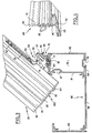
- fig. 1 représente une vue en perspective d'une première variante de réalisation du système de fixation conforme à la présente invention, à l'état démonté;
- fig. 2 représente un premier mode de montage d'un système de fixation conforme à la présente invention pour l'assemblage d'une pièce allongée de type chevron sur une structure porteuse;
- fig. 3 représente un second mode de montage d'un système de fixation conforme à la présente invention pour l'assemblage d'une pièce allongée de type chevron sur une structure porteuse;
- fig. 4 représente une vue en perspective d'un profilé de type chevron conforme aux fig. 2 et 3;
- fig. 5 représente une vue en perspective d'une seconde variante de réalisation du système de fixation conforme à la présente invention, à l'état démonté.
- fig. 1 shows a perspective view of a first alternative embodiment of the fixing system according to the present invention, in the disassembled state;
- fig. 2 shows a first method of mounting a fastening system according to the present invention for assembling an elongated chevron-type part on a support structure;
- fig. 3 shows a second method of mounting a fixing system according to the present invention for assembling an elongated chevron-type part on a support structure;
- fig. 4 shows a perspective view of a chevron type profile in accordance with FIGS. 2 and 3;
- fig. 5 shows a perspective view of a second alternative embodiment of the fastening system according to the present invention, in the disassembled state.
Comme cela apparaît sur la fig. 1, le système de fixation conforme à la présente invention se compose en combinaison de deux organes 10 et 50 formant respectivement pièce support 10 et équerre de montage 50.As shown in fig. 1, the fixing system in accordance with the present invention is made up of a combination of two
De préférence, la pièce support 10 est destinée à être fixée en position réglable sur une structure porteuse (80) et l'équerre de montage 50 est destinée à être fixée en position réglable sur une pièce (90) de type chevron qui sera dite chevron dans la suite de la description pour simplifier l'exposé, sans pour autant que cette expression soit limitative.Preferably, the
De même, pour simplifier l'exposé, la description détaillée qui va suivre s'applique au cas où la pièce support 10 est fixée sur une structure porteuse 80 et l'équerre de montage 50 sur un chevron 90, sans que cette disposition soit limitative.Similarly, to simplify the description, the detailed description which follows applies to the case where the
La pièce support 10 se compose d'une embase rectangulaire 11 généralement plane et de faible épaisseur qui est destinée à venir en appui sur l'extérieur d'une rainure à bords convergents prévue sur la structure porteuse 80 comme cela est représenté sur les fig. 2 et 3 et comme cela sera décrit plus en détails dans la suite de la description, ainsi que d'un prolongement arqué 13. L'embase 11 possède une largeur supérieure à l'ouverture de ladite rainure prévue sur la structure porteuse 80. Un orifice traversant 12 est ménagée dans la symétrie de l'embase 11. Cet orifice traversant 12 est destiné à autoriser le passage de la tige d'une vis 25 tout en formant une portée d'appui pour la tête 26 de celle-ci. Plus précisément, selon le mode de réalisation représenté sur la fig. 1, la tête 26 de la vis 25 est tronconique, par conséquent, pour éviter que la tête 26 de la vis 25 ne fasse saillie au-dessus de l'embase 11 on fraise l'orifice 12 en forme tronconique complémentaire de celle de la vis et ouverte du côté de l'embase 11 destinée à recevoir ladite vis 25.The
L'embase 11 est de plus associée à une pièce d'insert 20 dont la section droite est sensiblement complémentaire de la forme de ladite rainure prévue sur la structure porteuse 80. En l'occurence la section droite de l'insert 20 et de la rainure possède une forme dite en queue d'aronde, mais de nombreuses autres formes pourraient être adoptées dans le cadre de l'invention.The
Plus précisément, selon le mode de réalisation représenté fig. 1, l'insert 20 présente sur l'une de ses faces une nervure rectiligne 22 d'une largeur égale à l'ouverture de la rainure en queue d'aronde mais d'une épaisseur inférieure à l'épaisseur des bords convergents de celle-ci et deux décrochements 23 et 24 de part et d'autre de cette nervure 22.More specifically, according to the embodiment shown in fig. 1, the
Comme cela est représenté sur les fig. 2 et 3, la nervure 22 est destinée à pénétrer dans l'ouverture de la rainure en queue d'aronde de la structure porteuse tandis que les deux décrochements 23 et 24 sont destinés à venir en appui contre la surface interne des bords convergents de ladite rainure.As shown in Figs. 2 and 3, the
De plus, la pièce d'insert 20 possède dans sa symétrie un orifice traversant taraudé 21. Ainsi lorsque l'insert 20 est glissé dans la rainure en queue d'aronde de la structure porteuse 80, et amené en vis à vis de l'embase 11 de la pièce support 10 on peut aisément immobiliser en position appropriée la pièce support 10 sur la structure porteuse 80 par pincement des bords convergents de la rainure entre l'embase 11 de la pièce support 10 d'une part et la pièce d'insert 20 d'autre part, grâce au serrage de la vis 25 dans l'orifice taraudé correspondant 21.In addition, the
Le prolongement 13 de la pièce support 10 se raccorde à l'embase 11 selon une ligne référencée 17 en arrivant sensiblement perpendiculairement à l'embase 11. Comme cela est représenté sur la fig. 1, le prolongement 13 est recourbé au-dessus de l'embase 11. Plus précisément, la section droite du prolongement 11 passant par un plan perpendiculaire à ladite ligne de raccordement 17, définit un arc de cercle de l'ordre d'au moins un quart de cercle, dont la concavité est tournée du côté de l'embase 11.The
Le prolongement 13 possède en outre, dans sa symétrie, une rainure 16 d'extension généralement perpendiculaire à la ligne de raccordement 17 précitée et ouverte à l'opposé de celle-ci.The
La rainure 16 délimite ainsi dans le prolongement deux secteurs semi-cylindriques 14 et 15. La largeur de la rainure 16 est déterminée de façon telle qu'elle autorise le passage de la tige 32 d'une vis 30, mais non point de la tête 31 de celle-ci, de telle sorte que les deux secteurs semi-cylindriques 14 et 15 jouent le rôle de portée d'appui pour cette tête 31 de vis.The
De préférence, le rayon de courbure du prolongement 13 de la pièce support 10 est déterminé de façon telle que, la tête 31 de la vis 30 qui compose les organes de fixation étant positionnée du côté concave du prolongement 13, il provoque, lors du serrage, un blocage en rotation de la vis 30.Preferably, the radius of curvature of the
L'équerre de montage 50 se compose de deux branches 51, 55 perpendiculaires entre elles.The mounting
Une première branche 51 de forme rectangulaire est destinée à assurer la fixation de l'équerre de montage 50 sur le chevron 90. A cette fin cette première branche possède de préférence une section droite complémentaire d'une rainure à bords convergents prévue sur le chevron 90, telle qu'une rainure de forme dite en queue d'aronde. La première branche comporte également, dans sa symétrie, un orifice taraudé 52 traversant l'épaisseur de la branche, apte à recevoir une vis de pression 53 susceptible d'être portée en appui contre le fond de la rainure en queue d'aronde lors du serrage dans le filetage de l'orifice taraudé 52, pour immobiliser en position appropriée l'équerre de montage 50 sur le chevron 90 comme cela est représenté sur les fig. 2 et 3.A
La seconde branche 55 de l'équerre de montage 50, dont le plan est sensiblement perpendiculaire au plan de la première, possède une forme rectangulaire allongée et comporte dans sa symétrie en trou oblong 56 traversant son épaisseur.The
La seconde branche 55 est destinée, en position de fixation, à tangenter le prolongement 13 de la pièce support 10 dans une position telle que le trou oblong 56 se trouve en vis à vis de la rainure ouverte 16 pour permettre le passage de la tige 32 de la vis 30 sur laquelle est destiné à être serré un écrou 34 après interposition d'une rondelle de blocage 33.The
L'équerre de montage 50 peut être obtenue par simple pliage d'une pièce initialement rectiligne. Dans un tel cas la seconde branche possède une section droite identique à celle de la première branche. Toutefois, il est alors nécessaire, comme cela est représenté sur la fig. 1, de diminuer la largeur de l'équerre 50 au niveau de la zone de liaison entre les deux branches de telle sorte que la largeur de cette zone soit inférieure à la largeur de l'ouverture de la rainure en queue d'aronde prévue sur le chevron 90.The mounting
Bien entendu, le mode d'assemblage par pincement de la pièce support 10 sur la structure porteuse 80 qui vient d'être décrit peut être adopté pour assurer l'assemblage de l'équerre de montage 50 sur le chevron 90, et inversement.Of course, the method of assembly by pinching the
Les vis 25 et 53 précitées peuvent être avantageusement du type dit «vis à six pans creux», comme cela est représenté sur la fig. 1, sans pour autant que cette disposition soit limitative.The aforementioned screws 25 and 53 may advantageously be of the so-called “hexagon socket screw” type, as shown in FIG. 1, without this provision being limiting.
D'autre part, bien que selon le mode de réalisation représenté sur la fig. 1 la seconde branche 55 de l'équerre de montage 50 soit sensiblement rectiligne, on peut prévoir selon une variante de réalisation non représentée que la seconde branche 55 de l'équerre de montage 50 possède une forme générale courbée complémentaire du prolongement de la pièce support 10.On the other hand, although according to the embodiment shown in FIG. 1 the
On va maintenant décrire la variante de réalisation du système représentée sur la fig. 5.We will now describe the variant embodiment of the system shown in FIG. 5.
On va plus précisément décrire les différences existant entre cette variante et celle de la fig. 1. Les éléments similaires portent des références identiques et de ce fait ne seront pas redécrits.We will more precisely describe the differences between this variant and that of FIG. 1. Similar elements have identical references and therefore will not be described again.
Comme on peut le constater en comparant les deux variantes, la première branche 51 de l'équerre 50 a été rallongée et munie d'un second orifice taraudé 52', destiné à recevoir là encore une vis de pression 53.As can be seen by comparing the two variants, the
Plus précisément, tel que cela est représenté sur les fig. 2 et 3, la longueur de la première branche 51 et la position du second orifice taraudé 52' sont déterminées de telle sorte que quel que soit le mode de pose, le second orifice taraudé 52', et donc la vis 53 engagée dans celui-ci, soient constamment aisément accessibles.More specifically, as shown in Figs. 2 and 3, the length of the
De plus, l'embase 11 est munie sur sa surface opposée au prolongement arqué 13, d'une nervure ou saillie rectiligne 18 de largeur inférieure à l'ouverture séparant les bords convergents de la rainure présentée par la structure porteuse.In addition, the
En outre, l'épaisseur cumulée de cette saillie 18 et de la nervure 22 précitée doit être supérieure à l'épaisseur des bords convergents de la rainure.In addition, the cumulative thickness of this
Ainsi, lorsque l'insert 20 est glissé dans la rainure de la structure porteuse 80, la pièce support 10 peut être bloquée sur l'insert 20 grâce à une vis 26, tout en autorisant un glissement de l'ensemble ainsi formé dans la rainure.Thus, when the
De ce fait, la pièce support 10 est maintenue en rotation par la saillie 18 ce qui facilite le réglage ultérieur.Therefore, the
Bien entendu, on pourrait de même prévoir une seule nervure 18 ou 22, soit sur l'embase 11, soit sur l'insert 20, en donnant à cette nervure une épaisseur supérieure à l'épaisseur des bords convergents de la rainure.Of course, one could likewise provide a
En outre, l'insert 20 a été allongé par rapport à la variante de réalisation représentée sur la fig. 1, et deux orifices taraudés traversants 27 sont prévus respectivement de part et d'autre de l'orifice taraudé 21 précité. Les orifies 27 sont destinés à recevoir de vis de pression permettant l'immobilisation de l'insert 20 dans une rainure correspondante. La distance séparant ces orifices taraudés 27 est supérieure à la largeur de l'embase 11 de telle sorte que ces orifices 27 soient accessibles de part et d'autre de celle-ci.In addition, the
La structure porteuse 80 et le chevron 90 qui sont représentés sur les fig. 2 à 4 ne seront décrits que succinctement pour la bonne compréhension de la présente invention. Bien entendu ces pièces de charpente pourront prendre de nombreuses formes de réalisation.The supporting
Les chevrons 90 représentés en particulier en perspective sur la fig. 4 sont avantageusement formés de profilés présentant, en section droite, une forme générale en T inversé. Lesdits chevrons profilés 90 sont formés d'une âme centrale 91 munie, de part et d'autre de deux rainures 92 à bords convergents en forme de queue d'aronde, destinée à recevoir des joints d'étanchéité ou par- closes. La base 93 des chevrons profilés 90 transversale à l'âme centrale 91, précitée, et par laquelle les chevrons 90 sont destinés à venir reposer sur les structures porteuses 80 est également munie, d'une rainure longitudinale 94 à bords convergents en forme de queue d'aronde ouverte vers l'extérieur et destinée à recevoir ladite première branche 51 de l'équerre de montage. La partie supérieure de l'âme centrale 91 est munie d'un épaississement 95 qui peut être utilisé par exemple pour la fixation de bavettes d'étanchéité (non représentées sur les figures).The
De plus, comme cela est représenté sur la fig. 4, l'âme centrale 91 du chevron 90 est avantageusement munie d'une structure longitudinale 96 se présentant en section droite sous la forme d'un «C». On pourra ainsi aisément assembler des pièces d'étanchéité latérales ou de finition (référencées 100 sur les fig. 2 et 3), en extrémité du chevron 90, à l'aide d'une vis 101 engagée dans l'orifice 96. Bien entendu cet orifice pourra prendre toutes formes appropriées.In addition, as shown in FIG. 4, the
La structure porteuse 80 représentée sur les fig. 2 et 3 en section droite, qui peut par exemple constituer une traverse de véranda ou de serre, se compose de deux toiles parallèles verticales 81 et 82 reliées entre elles et à leurs extrémités par deux parois horizontales 83 et 84 qui leur sont perpendiculaires, de façon à définir entre ces différentes cloisons une chambre 85. La paroi horizontale supérieure 83 possède avantageusement une rainure 86 à bords convergents de section droite en forme de queue d'aronde ouverte vers l'extérieur de la chambre 85. De façon similaire la toile verticale 81 possède au voisinage de sa partie supérieure une rainure 87 à bords convergents de section droite en forme de queue d'aronde ouverte également vers l'extérieur de la chambre 85.The supporting
Les deux rainures 86 et 87 sont destinées à recevoir la pièce d'insert 20 associée à la pièce support 10.The two
En outre, la paroi horizontale inférieure 84 se prolonge horizontalement, de côté de la toile verticale 81 précitée, par une aile 88 qui possède elle-même à son extrémité une aile 89 en saillie vers le haut.In addition, the lower
Les ailes 88 et 89 forment avantageusement, en coopération avec la toile 81, une gouttière.The
Il convient de noter que ladite gouttière permet de rendre invisible d'un côté le système de fixation conforme à la présente invention tandis que le même système est pratiquement rendu invisible de l'autre côté par la structure porteuse 80.It should be noted that said gutter makes it possible to make invisible on one side the fixing system according to the present invention while the same system is practically made invisible on the other side by the
Accessoirement, la paroi horizontale inférieure 84 comporte également une rainure 79 à bords convergents ouverte vers l'extérieur de la chambre 85, et de section droite en forme de queue d'aronde.Incidentally, the lower
Comme cela est représenté sur la fig. 2, dans le cas de pentes faibles, de l'ordre de 0 à 45°, tel que par exemple dans le cas de vérandas, la pièce d'insert 20 sera de préférence introduite dans la rainure 87 prévue sur la toile verticale 81 tandis que comme cela est représenté sur la fig. 3, dans le cas de pentes fortes de l'ordre de 45 à 90°, tel que par exemple le cas de serres, la pièce d'insert 20 sera de préférence introduite dans la rainure 86 prévue sur la paroi horizontale supérieure 83.As shown in fig. 2, in the case of slight slopes, of the order of 0 to 45 °, such as for example in the case of verandas, the
Selon le mode de réalisation représenté sur les fig. 2 et 3, le chevron 90 et la structure porteuse ou traverse 80 sont croisés, cette disposition permet notamment de supporter le chevron 90 en un point quelconque de sa longueur.According to the embodiment shown in FIGS. 2 and 3, the
Bien entendu, on pourra également disposer le chevron 90 et la structure porteuse dans une position non croisée, mais inclinée entre eux, de façon à supporter soit l'extrémité d'un chevron sur une traverse, soit un chevron sur l'extrémité d'une traverse, en utilisant le système représenté sur la fig. 1.Of course, we can also arrange the
Pour ce faire, il suffit de faire pivoter la pièce support 10 de 90° sur l'insert 20 introduit dans la rainure, selon le mode de réalisation représenté sur les fig. 2 et 3.To do this, it suffices to rotate the
A cette fin, l'embase 11 de la pièce support 10 devra posséder une largeur supérieure à la dimension de l'ouverture de la rainure correspondante.To this end, the
Le but du montage est de faire tangenter la seconde branche 55 de l'équerre de montage 50 comportant le trou oblong 56, sur le prolongement arqué 13 de la pièce support 10, par un mouvement vertical du chevron 90. Ce dernier est «articulé» de telle sorte que la vis 30 qui est de préférence préalablement inserrée dans le trou oblong 56 et munie de la rondelle 33 et de l'écrou 34 puisse se loger dans la rainure ouverte 16 de la pièce support, et qu'elle puisse être serrée pour lier définitivemenmt l'équerre de montage 50 sur la pièce support 10.The purpose of the assembly is to make the
On va maintenant décrire le mode d'assemblage du système de fixation conforme à la présente invention.We will now describe the method of assembling the fixing system according to the present invention.
L'insert de la pièce support 10, comportant un trou taraudé 21 dans sa symétrie, doit être glissé dans la rainure (86, 87) du profilé traverse (80).The insert of the
La pièce support 10 vient ensuite se poser sur l'insert, de manière à faire correspondre les deux trous 12 et 21.The
La vis 25 doit être engagée, et légèrement vissée, de manière à permettre le coulissement de la pièce support 10, ceci dans le but d'effectuer un réglage par translation, pour le système de la fig. 1, ou vissée totalement pour le système de la fig. 5.The
Lorsque la pièce support 10 est positionnée de façon appropriée pour déterminer l'entraxe précis des chevrons 90, la pièce support 10 est immobilisée, soit par serrage de la vis 25 (fig. 1) soit par serrage de vis de pression dans les orifices taraudés 27 (fig. 5).When the
L'équerre de montage 50, comportant une vis 30 munie de son écrou 34 (libre dans le trou oblong 56) est ensuite glissée dans la rainure (94) du chevron 90.The mounting
Lorsque cette équerre 50 est positionnée par réglage longitudinal (seconde branche 55 de l'équerre 50 tangente au prolongement argué 13 de la pièce support 10) la seconde branche 51 est immobilisée dans la rainure correspondante. Le chevron 90 doit être soulevé afin de pouvoir passer une clé pour le serrage de la vis pression 53 avec le système de la fig. 1.When this
Dans ce cas, lors de la descente du chevron 90, il convient de crocheter la vis 30 dans la rainure ouverte 16 de la pièce support 10.In this case, when the
Le serrage de l'écrou 34 de la vis 30 permet d'établir la liaison définitive du système, à savoir de l'équerre de montage 50 sur la pièce support 10.The tightening of the
De part la forme arquée du prolongement 13 de cette dernière (étudiée pour épouser tous les angles possibles), la tête 31 de la vis 30 est retenue prisonnière lors du serrage et ne peut plus se soulever.Due to the arched shape of the
En effet, même dans le cas de montage représenté sur la fig. 2, la vis 30 ne peut effectuer une rotation avec un rayon supérieur au rayon de l'arc de cercle du prolongement 13 de la pièce support 10, alors que précisément le chevron tendrait à opérer une rotation avec un tel rayon supérieur.Indeed, even in the case of assembly shown in FIG. 2, the
De plus, cet arc de cercle est calculé de façon à empêcher «la tête hexagonale» 31 de la vis 30 de tourner lors du serrage de l'écrou 34.In addition, this circular arc is calculated so as to prevent the “hexagonal head” 31 of the
Claims (12)
Applications Claiming Priority (2)
| Application Number | Priority Date | Filing Date | Title |
|---|---|---|---|
| FR8205567A FR2524584B1 (en) | 1982-03-31 | 1982-03-31 | SYSTEM FOR FIXING AN ELONGATED PART OF THE CHEVRON TYPE ON A CARRIER STRUCTURE |
| FR8205567 | 1982-03-31 |
Publications (2)
| Publication Number | Publication Date |
|---|---|
| EP0091361A1 EP0091361A1 (en) | 1983-10-12 |
| EP0091361B1 true EP0091361B1 (en) | 1986-05-14 |
Family
ID=9272614
Family Applications (1)
| Application Number | Title | Priority Date | Filing Date |
|---|---|---|---|
| EP83400653A Expired EP0091361B1 (en) | 1982-03-31 | 1983-03-29 | System for connecting a longitudinal member such as a purlin with a carrying structure |
Country Status (5)
| Country | Link |
|---|---|
| EP (1) | EP0091361B1 (en) |
| DE (1) | DE3363493D1 (en) |
| ES (1) | ES287783Y (en) |
| FR (1) | FR2524584B1 (en) |
| PT (1) | PT76471B (en) |
Families Citing this family (8)
| Publication number | Priority date | Publication date | Assignee | Title |
|---|---|---|---|---|
| GB2259926B (en) * | 1991-09-27 | 1995-04-26 | Scholes Ernest M H | Roofing component |
| ATE159311T1 (en) * | 1993-02-26 | 1997-11-15 | Alain Costa | SUNROOF |
| FR2757891B1 (en) * | 1996-12-27 | 1999-02-19 | Alcan France | DEVICE FOR ASSEMBLING STRUCTURE PROFILES, PARTICULARLY FOR A VERANDA ROOF OR THE LIKE |
| GB9906078D0 (en) | 1999-03-18 | 1999-05-12 | Ultraframe Uk Ltd | Roof construction |
| ES2246231T3 (en) * | 1999-04-23 | 2006-02-16 | Vkr Holding A/S | MOUNTING AND JOINT ACCESSORY FOR A PANEL AND PANEL SYSTEM THAT INCLUDES SUCH ACCESSORIES. |
| GB2402947B (en) * | 2001-05-26 | 2005-03-30 | Synseal Extrusions Ltd | Method of assembling a building construction |
| DE20212290U1 (en) * | 2002-08-09 | 2003-12-18 | Franz Viegener Ii Gmbh & Co. Kg | Holder for fastening of mounting points has at least one locating face extending at angle to base and provided with cut-out for engagement of fastening elements, with base connected to locating face by bend |
| GB2423094A (en) * | 2005-02-09 | 2006-08-16 | Planet Roof Systems Ltd | Connecting rafter to eaves beam |
Family Cites Families (5)
| Publication number | Priority date | Publication date | Assignee | Title |
|---|---|---|---|---|
| GB691488A (en) * | 1950-09-15 | 1953-05-13 | Ici Ltd | Improvements in or relating to methods of fitting curved sheets in building |
| FR143936A (en) * | 1964-09-18 | |||
| JPS5624733Y2 (en) * | 1976-11-02 | 1981-06-11 | ||
| US4261143A (en) * | 1979-07-20 | 1981-04-14 | Michael Rizzo | Pitched roof support structures |
| BE884247A (en) * | 1980-07-10 | 1981-01-12 | Aluglas P V B A | ALUMINUM ROOF CONSTRUCTION, MORE SPECIAL FOR VERANDA TERRACE COVERINGS, POOL COVERINGS AND THE LIKE |
-
1982
- 1982-03-31 FR FR8205567A patent/FR2524584B1/en not_active Expired
-
1983
- 1983-03-24 ES ES1983287783U patent/ES287783Y/en not_active Expired
- 1983-03-29 DE DE8383400653T patent/DE3363493D1/en not_active Expired
- 1983-03-29 EP EP83400653A patent/EP0091361B1/en not_active Expired
- 1983-03-29 PT PT76471A patent/PT76471B/en not_active IP Right Cessation
Also Published As
| Publication number | Publication date |
|---|---|
| DE3363493D1 (en) | 1986-06-19 |
| FR2524584A1 (en) | 1983-10-07 |
| ES287783U (en) | 1987-08-16 |
| PT76471A (en) | 1983-04-01 |
| ES287783Y (en) | 1988-03-01 |
| PT76471B (en) | 1985-11-18 |
| FR2524584B1 (en) | 1985-09-06 |
| EP0091361A1 (en) | 1983-10-12 |
Similar Documents
| Publication | Publication Date | Title |
|---|---|---|
| WO2006123062A2 (en) | Connecting part and a steerable connecting part arrangement | |
| EP0091361B1 (en) | System for connecting a longitudinal member such as a purlin with a carrying structure | |
| EP0227514B1 (en) | System to support façade covering elements, particularly folded sheet metal caissons | |
| EP0075509B1 (en) | Hinged girder composed of light metal sections | |
| FR3055914B1 (en) | DETACHABLE ADJUSTING DEVICE IN LENGTH | |
| FR2549933A1 (en) | I-shaped profiled beam, fasteners and assemblies for such beams | |
| EP0359638B1 (en) | Assembling device for sections | |
| EP0681069B1 (en) | Accessible suspended false ceiling | |
| FR2922237A1 (en) | Fastener for suspending panel of suspended ceiling to ceiling wall, has plate hooked in suspension to lower free flange of I-shaped beam for anchoring board in metallic suspension section so that section is maintained in suspension at beam | |
| EP2163703A1 (en) | Variably angled connection device between two hollow profiles | |
| EP0143055B1 (en) | Supporting structure for establishing a rim rafter for a roof truss | |
| EP3351811A1 (en) | Assembly kit for support structures, assembly method and support structures assembled using said assembly kit | |
| EP0615072B1 (en) | Connecting and blocking device between a support profile and a chevron or similar element | |
| FR2624153A1 (en) | SUPPORT STRUCTURE FOR ADDITIONAL CONSTRUCTIONS, ESPECIALLY OF THE GENRE VERANDAS OR THE LIKE | |
| FR2744166A1 (en) | Louvre window pivot | |
| FR2889236A1 (en) | ADJUSTABLE HINGE | |
| FR3046666A1 (en) | DEVICE FOR MAINTAINING TWO PHOTOVOLTAIC PANELS AND ASSOCIATED SOLAR INSTALLATION | |
| FR2753733A1 (en) | Device for mounting of hollow support post for internal partition used e.g. in offices | |
| FR2930610A1 (en) | FIXING ELEMENT COMPRISING AN NUT FOR OPEN PROFILE RAIL | |
| FR2769931A1 (en) | Mounting insert for fixing panel on support | |
| FR2896813A1 (en) | Sundeck arrangement for polygon shaped swimming pool, has connection device with junction covering part whose external end is extended by folded part supported under end faces of sundeck panel to be connected | |
| WO2011144879A1 (en) | Device for attaching a structure to a corrugated covering | |
| FR2682739A1 (en) | Angle bracket for joining two metal sections | |
| FR2981680A1 (en) | UNIVERSAL METALLIC HARDWARE | |
| EP1640527A1 (en) | Connecting device between railings |
Legal Events
| Date | Code | Title | Description |
|---|---|---|---|
| PUAI | Public reference made under article 153(3) epc to a published international application that has entered the european phase |
Free format text: ORIGINAL CODE: 0009012 |
|
| AK | Designated contracting states |
Designated state(s): BE CH DE FR GB IT LI LU NL |
|
| 17P | Request for examination filed |
Effective date: 19840227 |
|
| ITF | It: translation for a ep patent filed |
Owner name: CON LOR S.R.L. |
|
| GRAA | (expected) grant |
Free format text: ORIGINAL CODE: 0009210 |
|
| REG | Reference to a national code |
Ref country code: FR Ref legal event code: TP |
|
| AK | Designated contracting states |
Kind code of ref document: B1 Designated state(s): BE CH DE FR GB IT LI LU NL |
|
| REF | Corresponds to: |
Ref document number: 3363493 Country of ref document: DE Date of ref document: 19860619 |
|
| PLBE | No opposition filed within time limit |
Free format text: ORIGINAL CODE: 0009261 |
|
| STAA | Information on the status of an ep patent application or granted ep patent |
Free format text: STATUS: NO OPPOSITION FILED WITHIN TIME LIMIT |
|
| 26N | No opposition filed | ||
| REG | Reference to a national code |
Ref country code: CH Ref legal event code: PUE Owner name: ALCAN FRANCE |
|
| PGFP | Annual fee paid to national office [announced via postgrant information from national office to epo] |
Ref country code: LU Payment date: 19930217 Year of fee payment: 11 Ref country code: FR Payment date: 19930217 Year of fee payment: 11 |
|
| PGFP | Annual fee paid to national office [announced via postgrant information from national office to epo] |
Ref country code: BE Payment date: 19930218 Year of fee payment: 11 |
|
| ITPR | It: changes in ownership of a european patent |
Owner name: CAMBIO RAGIONE SOCIALE;TECHNAL S.A. |
|
| PGFP | Annual fee paid to national office [announced via postgrant information from national office to epo] |
Ref country code: CH Payment date: 19930317 Year of fee payment: 11 |
|
| PGFP | Annual fee paid to national office [announced via postgrant information from national office to epo] |
Ref country code: GB Payment date: 19930323 Year of fee payment: 11 |
|
| ITTA | It: last paid annual fee | ||
| PGFP | Annual fee paid to national office [announced via postgrant information from national office to epo] |
Ref country code: NL Payment date: 19930331 Year of fee payment: 11 |
|
| EPTA | Lu: last paid annual fee | ||
| PGFP | Annual fee paid to national office [announced via postgrant information from national office to epo] |
Ref country code: DE Payment date: 19930525 Year of fee payment: 11 |
|
| PG25 | Lapsed in a contracting state [announced via postgrant information from national office to epo] |
Ref country code: LU Free format text: LAPSE BECAUSE OF NON-PAYMENT OF DUE FEES Effective date: 19940329 Ref country code: GB Effective date: 19940329 |
|
| PG25 | Lapsed in a contracting state [announced via postgrant information from national office to epo] |
Ref country code: LI Effective date: 19940331 Ref country code: CH Effective date: 19940331 Ref country code: BE Effective date: 19940331 |
|
| BERE | Be: lapsed |
Owner name: ALCAN FRANCE Effective date: 19940331 |
|
| PG25 | Lapsed in a contracting state [announced via postgrant information from national office to epo] |
Ref country code: NL Effective date: 19941001 |
|
| NLV4 | Nl: lapsed or anulled due to non-payment of the annual fee | ||
| GBPC | Gb: european patent ceased through non-payment of renewal fee |
Effective date: 19940329 |
|
| PG25 | Lapsed in a contracting state [announced via postgrant information from national office to epo] |
Ref country code: FR Effective date: 19941130 |
|
| REG | Reference to a national code |
Ref country code: CH Ref legal event code: PL |
|
| PG25 | Lapsed in a contracting state [announced via postgrant information from national office to epo] |
Ref country code: DE Effective date: 19941201 |
|
| BECH | Be: change of holder |
Free format text: 940110 *ALCAN FRANCE |
|
| BECN | Be: change of holder's name |
Effective date: 19940110 |
|
| REG | Reference to a national code |
Ref country code: FR Ref legal event code: ST |