EP0091040A2 - Protective excess current circuit-breaking switch - Google Patents
Protective excess current circuit-breaking switch Download PDFInfo
- Publication number
- EP0091040A2 EP0091040A2 EP83103009A EP83103009A EP0091040A2 EP 0091040 A2 EP0091040 A2 EP 0091040A2 EP 83103009 A EP83103009 A EP 83103009A EP 83103009 A EP83103009 A EP 83103009A EP 0091040 A2 EP0091040 A2 EP 0091040A2
- Authority
- EP
- European Patent Office
- Prior art keywords
- lever
- contact
- overcurrent protection
- protection switch
- switch according
- Prior art date
- Legal status (The legal status is an assumption and is not a legal conclusion. Google has not performed a legal analysis and makes no representation as to the accuracy of the status listed.)
- Granted
Links
Images


Classifications
-
- H—ELECTRICITY
- H01—ELECTRIC ELEMENTS
- H01H—ELECTRIC SWITCHES; RELAYS; SELECTORS; EMERGENCY PROTECTIVE DEVICES
- H01H71/00—Details of the protective switches or relays covered by groups H01H73/00 - H01H83/00
- H01H71/10—Operating or release mechanisms
- H01H71/50—Manual reset mechanisms which may be also used for manual release
- H01H71/52—Manual reset mechanisms which may be also used for manual release actuated by lever
- H01H71/528—Manual reset mechanisms which may be also used for manual release actuated by lever comprising a toggle or collapsible link between handle and contact arm, e.g. sear pin mechanism
-
- H—ELECTRICITY
- H01—ELECTRIC ELEMENTS
- H01H—ELECTRIC SWITCHES; RELAYS; SELECTORS; EMERGENCY PROTECTIVE DEVICES
- H01H2300/00—Orthogonal indexing scheme relating to electric switches, relays, selectors or emergency protective devices covered by H01H
- H01H2300/046—Orthogonal indexing scheme relating to electric switches, relays, selectors or emergency protective devices covered by H01H using snap closing mechanisms
- H01H2300/048—Snap closing by latched movable contact, wherein the movable contact is held in a minimal distance from the fixed contact during first phase of closing sequence in which a closing spring is charged
Definitions
- the invention relates to an overcurrent protection switch with the features of the preamble of claim 1.
- a switch is known from DE-PS 593 512.
- the movement of the actuating element is transmitted to a pivotable contact arm which, together with a contact fixed to the housing, forms the main contact of the switch.
- a restraining stop cooperating with the actuating element ensures that the contact elements close suddenly (momentary activation) when the contact is switched on.
- the known switch has the disadvantage that relatively large masses are firmly coupled to the contact arm when it is switched on and off and thus influence its switching behavior. There is also a risk of false triggering due to fluttering movements of the armature of the magnetic release.
- the invention has for its object to design a switch of the type mentioned in such a way that it has a defined switching behavior with a compact design and uncomplicated handling.
- the contact arm rests in its central region on the retaining stop, which is part of a separate component that is independent of the contact arm, and takes it with it when it snaps into the closed position.
- This makes it possible to dispense with further parts of the switch lock which trigger the yielding closing movement of the restraint stop, which increases the operational reliability of the switch.
- the contact arm can freely move upwards into the open position, as a result of which the inertia of the locking mechanism does not have a negative effect on the switching time.
- a particularly simple and functional way of arranging and guiding the restraint stop teaches claim 2, it being emphasized that the release of the restraint stop is carried out directly and thus in a structurally simple manner by the actuating element itself.
- Claims 4 and 5 ensure that when the switch is switched off or overcurrent tripped, the retaining pawl jumps back into its retaining position.
- the spring exerts a torque on the retaining pawl via the projection, which it engages under, such that when the main contact opens, the retaining pawl securely latches behind the housing projection holding it in the retaining position and simultaneously exerts a system pressure directed against the actuating element.
- the characterizing features of claim 7 ensure that the hinged anchor remains quietly in its rest position and "sticks" to the shunt bend until the force exerted on it by the coil flow is greater than the holding force of the shunt bend. This prevents the armature from fluttering and thus prevents premature tripping if necessary.
- Claim 10 enables the switch lock according to the invention to be used in different switch housings, which simplifies the storage of components.
- Claim 11 is concerned with a special, particularly functional design of the transmission of the axial movement of a push button on the stretching lever.
- Claim 12 enables control of an auxiliary circuit switch known per se.
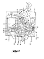
- the key switch (Fig. 2,3,5 to 7)
- the switch lock is operated manually via the rocker arm 1. This is rotatably mounted in the two housing halves with its pins 3 on both sides. In the drawing, the lower housing part 2 is shown. A joint 4 is arranged in the inner region of the rocker arm.
- the toggle lever element consisting of the first stretching lever 5 and the second stretching lever 6, is mounted on it, which in turn is rotatably connected by means of the knee joint 7.
- the lower end of the toggle lever element is articulated to the contact arm 9 via the bolt 8.
- the stretching lever 5 is approximately triangular and has a further pivot point 10 in the third corner, in which a latching lever 11 is mounted.
- the latch lever can hook with a catch 12 of the extension lever 6, so that the knee joint 7 becomes stiff.
- the latched knee joint is shown in FIG.
- the force component is aligned so that a left-turning torque is exerted on the rocker arm 1.
- the rocker arm 1 comes to rest in this position.
- the key switch is cocked.
- the force component of the tensioned switch lock is greater than the counterforce of the torsion spring (not shown) on the rocker arm 1.
- the knee joint 7 remains locked.
- the contacts are influenced solely by the rocker arm positions.
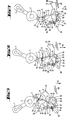
- the switch lock is triggered automatically via the magn.-hydr. Trigger 15.
- the hinged armature 16 When there is a corresponding overcurrent, the hinged armature 16 picks up and rotates about the pivot point 17. The arm 18 of the hinged armature 16 presses against the latching lever 11 and moves it upward. The latching between the latch lever 11 and the catch 12 of the extension lever 6 is released and the knee joint 7 collapses. This is caused by the torsion spring 19, which moves the contact arm 9 upwards by its spring force.
- the circle of the magnetic hydraulic release has a magnetic yoke 20 which is provided with a shunt bend 22 connected to the magnetic core 21.
- the yoke In the middle area, the yoke carries lateral tabs in which the parts of the key switch are stored and guided.
- the rest of the magnetic flux goes from the hinged armature 16 to the core 21.
- the hinged armature 16 can be fixed in its rest position more or less long. Only with larger currents does the pulling force between the hinged armature 16 and the core 21 prevail and the hinged armature 16 can tear away from its contact point on the shunt bend 22.
- the retaining pawl 23 is rotatably and displaceably mounted on the bolt 26.
- the retaining pawl 23 is pressed against the bolt 25 by the compression spring 24 (FIG. 5). If the key switch is moved to the switch-on position, the toggle lever element leads the contact arm 9 downwards. This movement is slowed down by the stop 28.
- the bolt 8 moves freely and unhindered in the backdrop 27. This position is shown in FIG. 7. When the rocker arm 1 moves further, the main contact 48 cannot close.
- the stop 28 acts as a fulcrum, so that the contact arm 9 is at its fulcrum 13 means of the bearing groove 57 moves.
- the coupling for manual actuation takes place on the rocker arms 1 by interposing the coupling piece 30.
- the parts mentioned are connected to one another by suitable mechanical elements. This is shown in FIG. 1 using a two-pole device consisting of two individual devices (device 31 and device 32).
- the operating lever 42 has two attachment points.
- the stop point 43 is moved downward by the contact arm 9. With it, the stop point 44 moves against the contact spring and causes it to snap.
- the current flows from the connection 45 to the coil of the magnetic hydraulic release 15, from this via a wire to the contact arm 9 and then via the contact pair to the connection 46.
- Quenching plates are arranged in the region of the contacts.
- the arc gases can be blown out via appropriate channels in the housing.
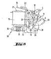
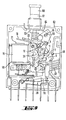
- Fig. 8 again shows the switch lock with magnetic release, which can be used as a prefabricated component in the housing of different dimensions and designs (Fig. 9 and Fig. 10).
- the actuating element is a push-pull button 60 which is axially displaceable in a screw sleeve 61 on the upper side 62 of the housing is arranged. Its inner end 63 interacts via an arm 64 by means of a pin 66 guided in an elongated hole 65 with a pivot lever 67 which converts the axial button movement into a pivoting movement and is pivotably mounted on an axis 68 fixed to the housing and with the first stretching lever 5 via a joint 69 connected is.
- the unit 58 corresponds in function and components to the switch already described.
- Auxiliary contacts 38 are arranged on the lower side of the housing facing away from the actuating element (push-pull button 60) and are actuated via an actuating lever 70 which interacts with the contact side of the contact arm 9.
- the assembly 58 is also used in the exemplary embodiment shown in FIG. 10 of a switch which can be placed on a switch rail, the actuating element also being designed as a rocker arm as in the first exemplary embodiment explained.
- the connection elements 71-74 for the main and auxiliary circuit are in the side area of the housing.
Abstract
Description
Die Erfindung betrifft einen Überstromschutzschalter mit den Merkmalen des Oberbegriffes des Patentanspruches 1. Ein derartiger Schalter ist aus DE-PS 593 512 bekannt. Mittels eines Kniehebelelementes wird die Bewegung des Betätigungselementes auf einen schwenkbaren Kontaktarm übertragen, der zusammen mit einem gehäusefesten Kontakt den Hauptkontakt des Schalters bildet. Ein mit dem Betätigungselement zusammenwirkender Rückhalteanschlag sorgt bei Einschaltung des Kontaktes für ein schlagartiges Schließen (Momenteinschaltung) der Kontaktelemente. Nachteilig wirkt sich bei dem bekannten Schalter aus, daß relativ große Massen bei Ein- und Ausschaltung an den Kontaktarm fest angekoppelt sind und somit sein Schaltverhalten beeinflussen. Außerdem besteht die Gefahr von Fehlauslösungen durch Flatterbewegungen des Ankers des Magnetauslösers.The invention relates to an overcurrent protection switch with the features of the preamble of
Der Erfindung liegt die Aufgabe zugrunde, einen Schalter der eingangs genannten Art derart auszubilden, daß er bei kompakter Bauweise und unkomplizierter Handhabung ein definierteres Schaltverhalten aufweist. Diese Aufgabe wird durch die kennzeichnenden Merkmale des Anspruches 1 gelöst.The invention has for its object to design a switch of the type mentioned in such a way that it has a defined switching behavior with a compact design and uncomplicated handling. These Object is solved by the characterizing features of
Erfindungsgemäß liegt der Kontaktarm in seinem Mittelbereich auf dem Rückhalteanschlag auf, der Bestandteil eines gesonderten, vom Kontaktarm unabhängigen Bauteils ist und nimmt diesen beim Einschnellen in die Schließstellung mit. Dadurch kann auf weitere, die nachgebende Schließbewegung des Rückhalteanschlages auslösende Teile des Schaltschlosses verzichtet werden, wodurch die Betriebssicherheit des Schalters erhöht wird. Insbesondere bei der Öffnungsbewegung kann der Kontaktarm ungehindert nach oben in die Öffnungsstellung schnellen, wodurch sich die Massenträgheit des Sperrmechanismus nicht negativ auf die Schaltzeit auswirkt. Eine besonders einfache und funktionelle Art der Anordnung und Führung des Rückhalteanschlages lehrt Anspruch 2, wobei hervorzuheben ist, daß die Freigabe des Rückhalteanschlages unmittelbar und damit auf baulich einfache Weise durch das Betätigungselement selbst erfolgt.According to the invention, the contact arm rests in its central region on the retaining stop, which is part of a separate component that is independent of the contact arm, and takes it with it when it snaps into the closed position. This makes it possible to dispense with further parts of the switch lock which trigger the yielding closing movement of the restraint stop, which increases the operational reliability of the switch. In particular during the opening movement, the contact arm can freely move upwards into the open position, as a result of which the inertia of the locking mechanism does not have a negative effect on the switching time. A particularly simple and functional way of arranging and guiding the restraint stop teaches
Durch die Ansprüche 4 und 5 ist dafür Sorge getragen, daß bei Ausschaltung bzw. Überstromauslösung des Schalters die Rückhalteklinke wieder in ihre Rückhaltestellung springt. Die Feder übt auf die Rückhalteklinke über den Vorsprung, welchen sie untergreift, ein derartiges Drehmoment auf, daß bei Öffnung des Hauptkontaktes die Rückhalteklinke sicher hinter dem sie in Rückhaltestellung haltenden Gehäusevorsprung verrastet und gleichzeitig einen gegen das Betätigungselement gerichteten Anlagedruck ausübt.
Durch die kennzeichnenden Merkmale des Anspruches 7 ist dafür Sorge getragen, daß der Klappanker solange ruhig in seiner Ruheposition verharrt und an der Nebenschlußabbiegung "klebt", bis die durch den Spulenfluß auf ihn ausgeübte Kraft größer ist als die Haltekraft der Nebenschlußabbiegung. Dadurch wird ein Flattern des Ankers und somit ein gegebenenfalls vorzeitiges Fehlauslösen vermieden.The characterizing features of
Durch Anspruch 9 können auf einfache Weise mehrere nebeneinanderriegende Schalter gleicher Bauart über "innere" Teile derart miteinander gekoppelt werden, daß bei Auslösung mindestens eines Schalters die neben ihm liegenden ebenfalls auslösen.By
Durch Anspruch 10 ist der Einsatz des erfindungsgemäßen Schaltschlosses in unterschiedlichen Schaltergehäusen ermöglicht, wodurch die Lagerhaltung von Bauteilen vereinfacht wird.
Anspruch 11 befaßt sich mit einer speziellen, besonders funktionellen Ausbildung der Übertragung der Axialbewegung eines Druckknopfes auf den Streckhebel.
Durch Anspruch 12 ist die Ansteuerung eines an sich bekannten Hilfsstromkreisschalters ermöglicht.
Die Erfindung ist anhand mehrerer in den Figuren der Zeichnung dargestellter Ausführungsbeispiele näher beschrieben. Es zeigen;
- Fig. 1 eine Gesamtansicht zweier, aneinander gekoppelter Schalter.
- Fig. 2 eine Innenansicht des Schalters in der Einschaltstellung.
- Fig. 3 eine Innenansicht in der Ausschaltstellung.
- Fig. 4 einen Querschnitt durch zwei gekoppelte Schalter mit der Darstellung der Kupplungsteile.
- Fig. 5 das Schaltschloß - schematisch in der Aus-Stellung.
- Fig. 6 das Schaltschloß - schematisch in der Stellung kurz vor der Momenteinschaltung der Hauptkontakte
- Fig. 7 das Schaltschloß - schematisch in der Ein-Stellung.
- Fig. 8 eine Ansicht des das Schaltschloß und den Magnetauslöser umfassenden einstückig vorgefertigten Baueinheit,
- Fig. 9 einen Schalter mit als Druckknopf ausgebildetem Betätigungselement,
- Fig. 10 eine weitere Bauform eines Schalters mit Kipphebelbetätigung.
- Fig. 1 is an overall view of two coupled switches.
- Fig. 2 is an interior view of the switch in the on position.
- Fig. 3 is an interior view in the off position.
- Fig. 4 shows a cross section through two coupled switches with the representation of the coupling parts.
- Fig. 5 the switch lock - schematically in the off position.
- Fig. 6, the switch lock - schematically in the position just before the main contacts are turned on
- Fig. 7 the switch lock - schematically in the on position.
- 8 is a view of the one-piece prefabricated unit comprising the switching lock and the magnetic release,
- 9 shows a switch with an actuating element designed as a push button,
- Fig. 10 shows another design of a switch with rocker arm actuation.
Die manuelle Betätigung des Schaltschlosses erfolgt über den Kipphebel 1. Dieser ist in den beiden Gehäusehälften mit seinen beidseitigen Zapfen 3 drehbar gelagert. In der Zeichnung ist das Gehäuse-Unterteil 2 dargestellt. Im inneren Bereich des Kipphebels ist ein Gelenk 4 angeordnet. An ihm lagert das Kniehebelelement, bestehend aus dem ersten Streckhebel 5 und dem zweiten Streckhebel 6, die ihrerseits mittels des Kniegelenkes 7 drehbar verbunden sind. Das untere Ende des Kniehebelelements= ist über den Bolzen 8 mit dem Kontaktarm 9 gelenkig verbunden. Der Streckhebel 5 ist etwa dreieckig gestaltet und hat in der dritten Ecke einen weiteren Drehpunkt 10, in dem ein Verklinkungshebel 11 gelagert ist. Der Verklinkungshebel kann mit einer Raste 12 des Streckhebels 6 verhaken, so daß das Kniegelenk 7 steif wird. In der Fig. 2 und in den Fig. 5 bis 7 wird das verrastete Kniegelenk gezeigt, dagegen ist in der Fig. 3 die Verrastung gelöst. Sobald das Kniegelenk 7 steif ist, kann bei der manuellen Betätigung des Kipphebels 1 der Kontaktarm 9 um seinen Drehpunkt 13 geschwenkt werden. Je nach der Betätigungsrichtung des Kipphebels werden die Kontakte geöffnet oder geschlossen.The switch lock is operated manually via the
In der Einschaltstellung ist die Kraftkomponente so ausgerichtet, daß auf den Kipphebel 1 ein linksdrehendes Moment ausgeübt wird. Durch den Anschlag 14 im Gehäuse kommt der Kipphebel 1 in dieser Stellung zur Ruhe. Das Schaltschloß ist gespannt. Die Kraftkomponente des gespannten Schaltschlosses ist größer als die Gegenkraft der Drehfeder (nicht dargestellt) am Kipphebel 1. Bei der manuellen Betätigung bleibt das Kniegelenk 7 verrastet. Die Kontakte werden allein durch die Kipphebelstellungen beeinflußt.In the switched-on position, the force component is aligned so that a left-turning torque is exerted on the
Die automatische Auslösung des Schaltschlosses erfolgt über den magn.-hydr. Auslöser 15.The switch lock is triggered automatically via the magn.-hydr. Trigger 15.
Bei entsprechendem Überstrom zieht der Klappanker 16 an und dreht sich dabei um den Drehpunkt 17. Der Arm 18 des Klappankers 16 drückt gegen den Verklinkungshebel 11 und bewegt diesen nach oben. Die Verrastung zwischen Verklinkungshebel 11 und der Raste 12 des Streckhebels 6 wird aufgehoben und das Kniegelenk 7 fällt zusammen. Dies wird durch die Drehfeder 19 bewirkt, die durch ihre Federkraft den Kontaktarm 9 nach oben bewegt.When there is a corresponding overcurrent, the hinged
Der magn. Kreis des magn.-hydraulischen Auslösers weist ein Magnet-Joch 20 auf, das mit einer in Verbindung mit dem Magnet-Kern 21 stehenden Nebenschlußabbiegung 22 versehen ist. Im mittleren Bereich trägt das Joch seitliche Lappen, in denen die Teile des Schaltschlosses gelagert und geführt sind.The magn. The circle of the magnetic hydraulic release has a
Der magnetische Fluß, der sich bei Stromdurchfluß in der Magnetspule ausbildet, verzweigt sich in Ruhestellung auch über die Nebenschlußabbiegung 22 und den Klappanker 16. Der Rest des Magnetflusses geht vom Klappanker 16 zum Kern 21. Durch entsprechende Querschnittwahl des Nebenschlusses kann der Klappanker 16 in seiner Ruhelage mehr oder weniger lange fixiert werden. Erst bei größeren Strömen überwiegt die Anzugskraft zwischen Klappanker 16 und Kern 21 und der Klappanker 16 kann sich von seinem Anlagepunkt an der Nebenschlußabbiegung 22 losreißen.The magnetic flux that flows in when the current flows the solenoid forms, branches in the rest position also via the
Die Moment-Einschaltung der Kontakte: Bei der Einschaltbewegung des Kipphebels 2 wird der Kontakthebel 9 kurz vor seiner endgültigen Schließung festgehalten und momentartig freigegeben, nachdem das Schaltschloß gespannt ist.The moment switching on of the contacts: When the
Dies bewirken folgende Teile:
- -
Rückhalteklinke 23 - -
Druckfeder 24 - -
Bolzen 25 - -
Bolzen 26 - -
Rüchhalteanschlag 28
- - Retaining
pawl 23 - -
compression spring 24 - -
bolt 25 - -
bolt 26 - -
Retention stop 28
Am Bolzen 26 ist die Rückhalteklinke 23 drehbar und verschiebbar gelagert. Durch die Druckfeder 24 wird die Rückhalteklinke 23 gegen den Bolzen 25 gedrückt (Fig. 5). Wird das Schaltschloß in die Einschaltstellung überführt, führt das Kniehebelelement den Kontaktarm 9 nach unten. Diese Bewegung wird durch den Anschlag 28 gebremst. Der Bolzen 8 bewegt sich dabei in der Kulisse 27 frei und ungehindert. In Fig. 7 ist diese Stellung dargestellt. Bei weiterer Bewegung des Kipphebels 1 kann sich der Hauptkontakt 48 nicht schließen. Der Anschlag 28 wirkt wie ein Drehpunkt, so daß sich der Kontaktarm 9 an seinem Drehpunkt 13 mittels der Lagernut 57 bewegt. Gleichzeitig kommt aber das Gelenk 4 des Kipphebels mit der Auslösenase 29 in Berührung und bewegt dadurch die Rückhalteklinke nach links, bis die Verrastung am Bolzen 25 feigegeben wird. Der Hauptkontakt schließt sich momentartig. Die Rückhalteklinke 23 wird durch den Anschlag 28 vom Kontaktarm 9 in Schließrichtung 51 mitgenommen und kann erst nach Öffnen der Kontakte wieder in ihre Verraststellung gelangen.The retaining
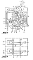
(Fig. 2,3 und 4 sowie Fig. 1): Die Kopplung mehrerer Einzelgeräte zu einer Funktionseinheit erfolgt sowohl bei manueller Betätigung als auch bei Überstromauslösung.(Fig. 2, 3 and 4 as well as Fig. 1): The coupling of several individual devices to a functional unit takes place both with manual actuation and with overcurrent tripping.
Die Kopplung für manuelle Betätigung erfolgt an den Kipphebeln 1 durch Zwischenschaltung des Kupplungsstückes 30. Die genannten Teile werden durch geeignete mechanische Elemente miteinander verbunden. In der Fig. 1 ist dies an Hand eines zweipoligen Gerätes, bestehend aus zwei Einzelgeräten (Gerät 31 und Gerät 32) gezeigt.The coupling for manual actuation takes place on the
Die Kopplung für die Überstromauslösung wird durch den Kopplungshebel 33 und die Kopplungsachse 34 hergestellt. Die Kopplungshebel 33 der nebeneinanderliegenden Geräte werden durch die Kopplungsachse 34, die durch die Gehäuseseitenwände hindurchragt, miteinander verbunden. Am Drehpunkt 36 ist der Kopplungshebel 33 im Gehäuse gelagert. Durch die Druckfeder 35 wird er rechtsdrehend nach unten bewegt und kommt dabei mit seinem Schenkel 37 am Bolzen 8 zum Anliegen. Löst nun ein Schalter automatisch durch seinen Magnet-Auslöser aus, dann bewegt sich der Bolzen 8 mit dem Kontaktarm 9 nach oben und nimmt den Kopplungshebel 33 mit. Dessen Schenkel 37 schlägt bei seiner Bewegung gegen den L-förmigen Lappen des Verklinkungshebels 11 (Fig. 4) und löst dabei die Verrastung des Kniegelenkes 7. Da die Achse 34 aber die Hebel 33 miteinander kuppelt, kommen auch die banachbarten Geräte zum Auslösen. In die Gehäuse-Teile sind auch Hilfskontakte eingelegt. (Fig. 2 und 3). Im gezeigten Beispiel handelt es sich um einen Wechsler mit folgenden Teilen:
- - Festkontakt-Öffner 39 (von der Aus-Stellung betrachtet),
- - Festkontakt-Schließer 40 (von der Aus-Stellung betrachtet),
- -
Kontaktfeder 41 in Schnappausführung, - -
Betätigungshebel 42.
- Fixed contact break contact 39 (viewed from the off position),
- Fixed contact make contact 40 (viewed from the off position),
- - snap
spring contact spring 41, - - operating
lever 42.
Der Betätigungshebel 42 hat zwei Anschlagpunkte. Der Anschlagpunkt 43 wird vom Kontaktarm 9 nach unten bewegt. Mit ihm bewegt sich der Anschlagpunkt 44 gegen die Kontaktfeder und bringt sie zum Umschnappen.The operating
Der Strom fließt vom Anschluß 45 zur Spule des magn.- hydraulischen Auslösers 15, von dieser über eine Litze zum Kontaktarm 9 und dann über das Kontaktpaar zum Anschluß 46. Im Bereich der Kontakte sind Löschbleche angeordnet. Die Ausblasung der Lichtbogengase kann über entsprechende Kanäle in den Gehäusen nach aussen erfolgen.The current flows from the
Fig. 8 zeigt nochmals das Schaltschloß mit Magnetauslösung, das als vorgefertigtes Bauteil in die Gehäuse unterschiedlicher Abmessungen und Ausbildungen (Fig. 9 und Fig. 10) eingesetzt werden kann. Bei dem in Fig. 9 gezeigten Ausführungsbeispiel ist das Betätigungselement ein Druck-Zug-Knopf 60, der in einer Schraubhülse 61 axial verschiebbar an der Gehäuseoberseite 62 angeordnet ist. Sein inneres Ende 63 wirkt über einen Arm 64 mittels eines in einem Langloch 65 geführten Zapfens 66 mit einer die axiale Knopfbewegung in eine Schwenkbewegung umsetzenden Schwenkhebel 67 zusammen, der auf einer gehäusefesten Achse 68 schwenkbar gelagert ist und mit dem ersten Streckhebel 5 über ein Gelenk 69 verbunden ist.Fig. 8 again shows the switch lock with magnetic release, which can be used as a prefabricated component in the housing of different dimensions and designs (Fig. 9 and Fig. 10). In the exemplary embodiment shown in FIG. 9, the actuating element is a push-
Die Baueinheit 58 entspricht in Funktion und Bauteilen dem bereits vorbeschriebenen Schalter.The
Auf der dem Betätigungselement (Druck-Zug-Knopf 60) abgewandten unteren Gehäuseseite sind Hilfskontakte 38 angeordnet, die über einen mit der Kontaktseite des Kontaktarmes 9 zusammenwirkenden Stellhebel 70 betätigt werden.
Auch in dem in Fig. 10 gezeigten Ausführungsbeispiel eines auf eine Schalterschiene aufsetzbaren Schalters ist die Baueinheit 58 verwendet, wobei das Betätigungselement wie beim ersterläuterten Ausführungsbeispiel auch als Kipphebel ausgebildet ist. Allerdings liegen die Anschlußelemente 71-74 für Haupt- und Hilfsstromkreis im Seitenbereich des Gehäuses.The
- 1 Kipphebel1 rocker arm
- 2 Gehäuse-Unterteil2 lower housing part
- 3 Zapfen3 cones
- 4 Gelenk4 joint
- 5 erster Streckhebel5 first extension lever
- 6 zweiter Streckhebel6 second extension lever
- 7 Kniegelenk7 knee joint
- 8 Bolzen8 bolts
- 9 Kontaktarm9 contact arm
- 10 Drehpunkt10 pivot point
- 11 Verklinkungshebel11 latch lever
- 12 Raste12 notches
- 13 Drehpunkt13 pivot point
- 14 Anschlag14 stop
- 15 mangetisch-hydraulischer Auslöser15 mangetic-hydraulic release
- 16 Klappanker16 folding anchors
- 17 Drehpunkt17 pivot point
- 18 Arm18 arm
- 19 Drehfeder19 torsion spring
- 20 Magnet-Joch20 magnetic yoke
- 21 Magnet-Kern21 magnetic core
- 22 Nebenschlußabbiegung22 Shunt bend
- 23 Rückhalteklinke23 retention pawl
- 24 Druckfeder24 compression spring
- 25 Bolzen25 bolts
- 26 Bolzen26 bolts
- 27 Kulisse27 backdrop
- 28 Rückhalteanschlag28 Restraint stop
- 29 Auslösenase29 release lug
- 30 Kupplungsstück30 coupling piece
- 31 Gerät31 device
- 32 Gerät32 device
- 33 Kopplungshebel33 coupling lever
- 34 Kopplungsachse34 coupling axis
- 35 Druckfeder35 compression spring
- 36 Drehpunkt36 pivot point
- 37 Schenkel37 legs
- 38 Hilfskontakte38 auxiliary contacts
- 39 Festkontakt-Öffner39 fixed contact break contact
- 40 Festkontakt-Schließer40 fixed contact make contacts
- 41 Kontaktfeder41 contact spring
- 42 Betätigungshebel42 operating lever
- 43 Anschlagpunkt43 anchor point
- 44 Anschlagpunkt44 anchor point
- 45 Anschluß45 connection
- 46 Anschluß46 connection
-
47 Wirkende v. 647
Actors 6 - 48 Hauptkontakt48 main contact
- 49 Kontaktende49 contacts
- 50 Gelenkende50 hinge ends
- 51 Schließrichtung51 closing direction
- 52 Ende v. 2352 end of 23
-
53 Betätigungsende v. 2353 end of
actuation 23 - 54 Mittelbereich v. 2354 middle range from 23
- 55 Durchbrechung55 breakthrough
- 56 Rast-L-Schenkel v. 5556 locking L-legs from 55
- 57 Lagernut57 bearing groove
- 58 Baueinheit58 unit
- 60 Druck-Zugknopf60 push-pull button
- 61 Schraubhülse61 screw sleeve
- 62 Gehäuseoberseite62 Top of housing
- 63 inneres Ende63 inner end
- 64 Arm64 arm
- 65 Langloch65 slot
- 66 Zapfen66 cones
- 67 Schwenkhebel67 swivel levers
- 68 Achse68 axis
- 69 Gelenk69 joint
- 70 Stellhebel70 control levers
- 71 Anschlußelemente71 connection elements
Claims (15)
dadurch gekennzeichnet, daß
characterized in that
dadurch gekennzeichnet,
daß die Rückhalteklinke (23) sich im wesentlichen entlang des Kniehebelelementes (Streckhebel 5,6) erstreckt, an ihrem hauptkontaktseitigen Ende (52) den den Kontaktarm (9) untergreifenden Rückhalteanschlag (28) und an ihrem Betätigungsende (53) eine Auslösenase (29) aufweist, die seitlich durch das innere Ende (Gelenk 4) des Betätigungselementes (Kipphebel 1) verschiebbar ist.2. Overcurrent protection switch according to claim 1,
characterized,
that the retaining pawl (23) extends essentially along the toggle lever element (extension lever 5, 6), at its main contact-side end (52) the retaining stop (28) engaging under the contact arm (9) and at its actuating end (53) a release lug (29) has which is laterally displaceable through the inner end (joint 4) of the actuating element (rocker arm 1).
dadurch gekennzeichnet,
daß die Rückhalteklinke (23) in ihrem Mittelbereich (54) eine im wesentlichen L-förmige Durchbrechung (55) aufweist, in deren im wesentlichen rechtwinklig zur Schließrichtung (51) verlaufenden Rast-L-Schenkel (56) in Rückhaltestellung (Fig. 5,6) der als Bolzen (25) ausgebildete Gehäusevorsprung einliegt.3. Overcurrent protection switch according to at least one of the preceding claims,
characterized,
that the retaining pawl (23) has an essentially L-shaped opening (55) in its central region (54), in its latching L-leg (56), which runs essentially at right angles to the closing direction (51), in the retaining position (Fig. 5, 6) the housing projection formed as a bolt (25) lies.
dadurch gekennzeichnet,
daß die Rückhalteklinke (23) mittels einer Feder (24) in Richtung auf das Betätigungselement (Kipphebel 1) vorgespannt ist.4. Overcurrent protection switch according to at least one of the preceding claims
characterized,
that the retaining pawl (23) is biased by a spring (24) in the direction of the actuating element (rocker arm 1).
dadurch gekennzeichnet,
daß die Feder (Druckfeder 24) einen in Richtung des Rast-L-Schenkels (56) der Durchbrechung (55) von der Rückhalteklinke (23) abstehenden Vorsprung (58) untergreift.5. Overcurrent protection switch according to at least one of the preceding claims,
characterized,
that the spring (compression spring 24) engages under a projection (58) projecting in the direction of the latching L-leg (56) of the opening (55) from the retaining pawl (23).
dadurch gekennzeichnet,
daß der Kontakthebel (9) mittels einer im wesentlichen in Schließrichtung (51) in dem Gelenkende (50) verlaufenden Lagernut (57) auf einem Gehäusezapfen (Drehpunkt 13) gelagert ist.6. Overcurrent protection switch according to at least one of the preceding claims
characterized,
that the contact lever (9) is mounted on a housing pin (pivot point 13) by means of a bearing groove (57) running essentially in the closing direction (51) in the joint end (50).
dadurch gekennzeichnet,
daß das Magnetjoch (20) auf der Seite des Klappankers (16) über das Spulenende hinaussteht und eine den Klappanker (16) übergreifende L-förmige Nebenschlußabbiegung (22) aufweist.7. Overcurrent protection switch according to at least one of the preceding claims, having a trigger (15) consisting essentially of a coil with a magnetic core (21) and magnetic yoke (20) and having a folding armature (16) acting on the knee joint (7) of the switch,
characterized,
that the magnetic yoke (20) on the side of the hinged armature (16) projects beyond the coil end and has an L-shaped shunt bend (22) overlapping the hinged armature (16).
dadurch gekennzeichnet,
daß der Klappanker (16) in Ruhestellung an der der Spule zugewandten Seite der Nebenschlußabbiegung (22) anliegt.8. Overcurrent protection switch according to at least one of the preceding claims,
characterized,
that the hinged armature (16) rests in the rest position on the side of the shunt bend (22) facing the coil.
dadurch gekennzeichnet,
daß mit dem Kontaktarm (9) ein Kopplungshebel (33) wirkverbunden ist, dessen Wirkende (Schenkel 37) das Kniegelenk (7) in Freigaberichtung beaufschlagt und der eine Kopplungsachse (34) zum Eingriff in mindestens einen zum Schalter benachbart angeordneten Überstromschutzschalter (Geräte 31,32 in Fig. 1 und 4) trägt und mit dessen Kopplungshebel verbunden ist.9. Overcurrent protection switch according to at least one of the preceding claims
characterized,
that a coupling lever (33) is operatively connected to the contact arm (9), the operative end (leg 37) of which acts on the knee joint (7) in the release direction and the one coupling axis (34) for engagement in at least one overcurrent protection switch (devices 31, 32 in Fig. 1 and 4) carries and is connected to the coupling lever.
dadurch gekennzeichnet,
daß das Schaltschloß (im wesentlichen 5-13,23-29) und der Auslöser (im wesentlchen 15-22) als einstückig vorgefertigte Baueinheit (58) in Gehäuse unterschiedlicher Bauart und Funktion einsetzbar sind.10. Overcurrent protection switch according to at least one of the preceding claims,
characterized,
that the switch lock (essentially 5-13,23-29) and the trigger (essentially 15-22) can be used as a one-piece prefabricated unit (58) in housings of different types and functions.
dadurch gekennzeichnet,
daß die Handhabe des Betätigungselementes als axialverschiebbarer Druckknopf ausgebildet ist, dessen inneres Ende mit einem den ersten Streckhebel der Baueinheit betätigenden, die axiale Bewegung in Schwenkbewegung umsetzender Schwenkhebel verbunden ist.11. Overcurrent protection switch according to at least one of the preceding claims,
characterized,
that the handle of the actuating element is designed as an axially displaceable push button, the inner end of which is connected to a pivot lever which actuates the first stretching lever of the structural unit and converts the axial movement into pivoting movement.
dadurch gekennzeichnet,
daß in der den Betätigungselementen abgewandter Gehäuseseite ein oder mehrere Hilfskontaktschalter angeordnet sind, die über einen mit der Kontaktseite des Kontaktarmes zusammenwirkenden Stellhebel betätigbar sind.12. Overcurrent protection switch according to at least one of the preceding claims,
characterized,
that one or more auxiliary contact switches are arranged in the housing side facing away from the actuating elements and can be actuated via an actuating lever which interacts with the contact side of the contact arm.
Applications Claiming Priority (2)
| Application Number | Priority Date | Filing Date | Title |
|---|---|---|---|
| DE3212474A DE3212474C2 (en) | 1982-04-03 | 1982-04-03 | Overcurrent protection switch |
| DE3212474 | 1982-04-03 |
Publications (3)
| Publication Number | Publication Date |
|---|---|
| EP0091040A2 true EP0091040A2 (en) | 1983-10-12 |
| EP0091040A3 EP0091040A3 (en) | 1985-03-27 |
| EP0091040B1 EP0091040B1 (en) | 1987-06-03 |
Family
ID=6160177
Family Applications (1)
| Application Number | Title | Priority Date | Filing Date |
|---|---|---|---|
| EP83103009A Expired EP0091040B1 (en) | 1982-04-03 | 1983-03-26 | Protective excess current circuit-breaking switch |
Country Status (2)
| Country | Link |
|---|---|
| EP (1) | EP0091040B1 (en) |
| DE (3) | DE3212474C2 (en) |
Cited By (7)
| Publication number | Priority date | Publication date | Assignee | Title |
|---|---|---|---|---|
| EP0146528A2 (en) * | 1983-11-28 | 1985-06-26 | Felten & Guilleaume Fabrik elektrischer Apparate Aktiengesellschaft Schrems-Eugenia Niederösterreich | Switching mechanism for a protective power circuit breaker |
| GB2176659A (en) * | 1985-05-01 | 1986-12-31 | Mitsubishi Electric Corp | Circuit interrupter |
| FR2654253A1 (en) * | 1989-11-03 | 1991-05-10 | Schupa Elektro Gmbh & Co Kg | DEVICE FOR THE CLOSURE OF THE MOBILE LEVER CONNECTIONS, IN PARTICULAR FOR A BIPOLAR BREAKER FOR PROTECTION AGAINST LEAKAGE CURRENTS. |
| EP0847070A3 (en) * | 1996-02-06 | 1998-11-04 | Rockwell Automation AG | Over current circuit breaker, particularly motor circuit breaker |
| EP2688085A1 (en) * | 2012-07-17 | 2014-01-22 | Abb Ag | Electric installation switching device |
| EP3767660A1 (en) * | 2019-07-16 | 2021-01-20 | Eaton Intelligent Power Limited | A switching device |
| WO2022028849A1 (en) * | 2020-08-07 | 2022-02-10 | Siemens Aktiengesellschaft | Operator-independent compact spring-action switching mechanism and electromechanical protective switching device |
Families Citing this family (1)
| Publication number | Priority date | Publication date | Assignee | Title |
|---|---|---|---|---|
| DE102019219314A1 (en) * | 2019-12-11 | 2021-06-17 | Siemens Aktiengesellschaft | Electrical switch with a locking mechanism |
Citations (3)
| Publication number | Priority date | Publication date | Assignee | Title |
|---|---|---|---|---|
| US2700711A (en) * | 1951-12-14 | 1955-01-25 | Heinemann Electric Co | Automatic circuit breaker |
| DE1187722B (en) * | 1960-05-17 | 1965-02-25 | Licentia Gmbh | Circuit breakers with electromagnetic and / or thermal releases |
| DE2132738B1 (en) * | 1971-07-01 | 1972-07-06 | Ellenberger & Poensgen | Single or multi-pole overcurrent switch with thermal and / or electromagnetic release |
Family Cites Families (6)
| Publication number | Priority date | Publication date | Assignee | Title |
|---|---|---|---|---|
| DE593512C (en) * | 1934-02-27 | Siemens Schuckertwerke Akt Ges | Installation circuit breaker with instant activation | |
| CH178667A (en) * | 1933-07-04 | 1935-07-31 | Stotz Kontakt Gmbh | Device for instantaneous switching on electrical switches. |
| DE959291C (en) * | 1950-05-25 | 1957-03-07 | Siemens Ag | Electromagnetic overcurrent release for alternating current |
| US3329912A (en) * | 1965-10-01 | 1967-07-04 | Wood Electric Corp | Multipole circuit breaker with interconnected toggle locks and contact members |
| DE2015624A1 (en) * | 1970-04-02 | 1971-10-21 | Bbc Brown Boveri & Cie | Auto switch |
| DE2656877A1 (en) * | 1975-12-22 | 1977-07-07 | Mitsubishi Electric Corp | Electromagnetic excess current cut-out - has nonmagnetic case containing movable magnet and section of damping oil |
-
1982
- 1982-04-03 DE DE3212474A patent/DE3212474C2/en not_active Expired
- 1982-04-03 DE DE8209597U patent/DE8209597U1/de not_active Expired
-
1983
- 1983-03-26 EP EP83103009A patent/EP0091040B1/en not_active Expired
- 1983-03-26 DE DE8383103009T patent/DE3371959D1/en not_active Expired
Patent Citations (3)
| Publication number | Priority date | Publication date | Assignee | Title |
|---|---|---|---|---|
| US2700711A (en) * | 1951-12-14 | 1955-01-25 | Heinemann Electric Co | Automatic circuit breaker |
| DE1187722B (en) * | 1960-05-17 | 1965-02-25 | Licentia Gmbh | Circuit breakers with electromagnetic and / or thermal releases |
| DE2132738B1 (en) * | 1971-07-01 | 1972-07-06 | Ellenberger & Poensgen | Single or multi-pole overcurrent switch with thermal and / or electromagnetic release |
Cited By (11)
| Publication number | Priority date | Publication date | Assignee | Title |
|---|---|---|---|---|
| EP0146528A2 (en) * | 1983-11-28 | 1985-06-26 | Felten & Guilleaume Fabrik elektrischer Apparate Aktiengesellschaft Schrems-Eugenia Niederösterreich | Switching mechanism for a protective power circuit breaker |
| EP0146528A3 (en) * | 1983-11-28 | 1987-01-21 | Felten & Guilleaume Fabrik Elektrischer Apparate Aktiengesellschaft Schrems-Eugenia Niederosterreich | Switching mechanism for a protective power circuit breaker |
| GB2176659A (en) * | 1985-05-01 | 1986-12-31 | Mitsubishi Electric Corp | Circuit interrupter |
| US4743878A (en) * | 1985-05-01 | 1988-05-10 | Mitsubishi Denki Kabushiki Kaisha | Circuit interrupter |
| GB2176659B (en) * | 1985-05-01 | 1989-05-10 | Mitsubishi Electric Corp | Circuit interrupter |
| FR2654253A1 (en) * | 1989-11-03 | 1991-05-10 | Schupa Elektro Gmbh & Co Kg | DEVICE FOR THE CLOSURE OF THE MOBILE LEVER CONNECTIONS, IN PARTICULAR FOR A BIPOLAR BREAKER FOR PROTECTION AGAINST LEAKAGE CURRENTS. |
| BE1005375A0 (en) * | 1989-11-03 | 1993-07-06 | Schupa Elektro Gmbh & Co Kg | Device engagement of a sudden lever contact mobile monte way, especially for a switch protection of fault current. |
| EP0847070A3 (en) * | 1996-02-06 | 1998-11-04 | Rockwell Automation AG | Over current circuit breaker, particularly motor circuit breaker |
| EP2688085A1 (en) * | 2012-07-17 | 2014-01-22 | Abb Ag | Electric installation switching device |
| EP3767660A1 (en) * | 2019-07-16 | 2021-01-20 | Eaton Intelligent Power Limited | A switching device |
| WO2022028849A1 (en) * | 2020-08-07 | 2022-02-10 | Siemens Aktiengesellschaft | Operator-independent compact spring-action switching mechanism and electromechanical protective switching device |
Also Published As
| Publication number | Publication date |
|---|---|
| EP0091040B1 (en) | 1987-06-03 |
| DE3212474A1 (en) | 1983-10-13 |
| DE3212474C2 (en) | 1986-02-06 |
| DE3371959D1 (en) | 1987-07-09 |
| DE8209597U1 (en) | 1986-11-13 |
| EP0091040A3 (en) | 1985-03-27 |
Similar Documents
| Publication | Publication Date | Title |
|---|---|---|
| EP1760747B1 (en) | Electric circuit breaker | |
| EP1760748B1 (en) | Electrical switching device | |
| EP2634787B1 (en) | Switching lock of a circuit breaker | |
| DE4304771C1 (en) | Switching device for multi-phase motor protection switch - cooperates with release lever of external auxiliary switch upon overcurrent release | |
| EP0892420A2 (en) | Locking mechanism for an electrical excesscurrent switch for motor protection | |
| EP0091040B1 (en) | Protective excess current circuit-breaking switch | |
| DE2507454C2 (en) | MULTI-POLE OVERCURRENT SWITCH | |
| DE2115034B2 (en) | CIRCUIT BREAKER WITH OVERCURRENT, SHORT CIRCUIT AND FAULT CURRENT PROTECTION | |
| DE3119165C2 (en) | Circuit breaker as a unit consisting of a circuit breaker as well as auxiliary and signal switches | |
| DE827984C (en) | Auto switch | |
| EP0680661B1 (en) | Line safety switch | |
| EP1005060B1 (en) | Undervoltage release device | |
| DE4122268C2 (en) | ||
| EP0147629B1 (en) | Protective circuit breaker | |
| DE3643511C2 (en) | ||
| DE10322654A1 (en) | switchgear | |
| DE4339425B4 (en) | Switch lock for a residual current circuit breaker | |
| EP0731979B1 (en) | Safety switch | |
| EP0849759B1 (en) | Switchgear for an electric installation | |
| DE2904211C2 (en) | Residual current circuit breaker that is coupled to a line circuit breaker | |
| EP1659604B1 (en) | Switchgear for an electric installation | |
| EP0127784A1 (en) | Overcurrent circuit breaker | |
| EP0146528B1 (en) | Switching mechanism for a protective power circuit breaker | |
| DE3049518C2 (en) | Lock mechanism for a low-voltage circuit breaker | |
| DE3347097A1 (en) | Protection circuit breaker |
Legal Events
| Date | Code | Title | Description |
|---|---|---|---|
| PUAI | Public reference made under article 153(3) epc to a published international application that has entered the european phase |
Free format text: ORIGINAL CODE: 0009012 |
|
| AK | Designated contracting states |
Designated state(s): CH DE FR GB IT LI |
|
| ITCL | It: translation for ep claims filed |
Representative=s name: RICCARDI SERGIO & CO. |
|
| EL | Fr: translation of claims filed | ||
| PUAL | Search report despatched |
Free format text: ORIGINAL CODE: 0009013 |
|
| AK | Designated contracting states |
Designated state(s): CH DE FR GB IT LI |
|
| 17P | Request for examination filed |
Effective date: 19850430 |
|
| 17Q | First examination report despatched |
Effective date: 19860319 |
|
| GRAA | (expected) grant |
Free format text: ORIGINAL CODE: 0009210 |
|
| AK | Designated contracting states |
Kind code of ref document: B1 Designated state(s): CH DE FR GB IT LI |
|
| REF | Corresponds to: |
Ref document number: 3371959 Country of ref document: DE Date of ref document: 19870709 |
|
| ET | Fr: translation filed | ||
| ITF | It: translation for a ep patent filed |
Owner name: UFFICIO BREVETTI RICCARDI & C. |
|
| PLBE | No opposition filed within time limit |
Free format text: ORIGINAL CODE: 0009261 |
|
| STAA | Information on the status of an ep patent application or granted ep patent |
Free format text: STATUS: NO OPPOSITION FILED WITHIN TIME LIMIT |
|
| 26N | No opposition filed | ||
| ITTA | It: last paid annual fee | ||
| PGFP | Annual fee paid to national office [announced via postgrant information from national office to epo] |
Ref country code: DE Payment date: 19970204 Year of fee payment: 15 |
|
| PGFP | Annual fee paid to national office [announced via postgrant information from national office to epo] |
Ref country code: GB Payment date: 19970305 Year of fee payment: 15 |
|
| PGFP | Annual fee paid to national office [announced via postgrant information from national office to epo] |
Ref country code: FR Payment date: 19970319 Year of fee payment: 15 |
|
| PGFP | Annual fee paid to national office [announced via postgrant information from national office to epo] |
Ref country code: CH Payment date: 19970324 Year of fee payment: 15 |
|
| PG25 | Lapsed in a contracting state [announced via postgrant information from national office to epo] |
Ref country code: GB Free format text: LAPSE BECAUSE OF NON-PAYMENT OF DUE FEES Effective date: 19980326 |
|
| PG25 | Lapsed in a contracting state [announced via postgrant information from national office to epo] |
Ref country code: LI Free format text: LAPSE BECAUSE OF NON-PAYMENT OF DUE FEES Effective date: 19980331 Ref country code: FR Free format text: THE PATENT HAS BEEN ANNULLED BY A DECISION OF A NATIONAL AUTHORITY Effective date: 19980331 Ref country code: CH Free format text: LAPSE BECAUSE OF NON-PAYMENT OF DUE FEES Effective date: 19980331 |
|
| REG | Reference to a national code |
Ref country code: CH Ref legal event code: PL |
|
| GBPC | Gb: european patent ceased through non-payment of renewal fee |
Effective date: 19980326 |
|
| PG25 | Lapsed in a contracting state [announced via postgrant information from national office to epo] |
Ref country code: DE Free format text: LAPSE BECAUSE OF NON-PAYMENT OF DUE FEES Effective date: 19981201 |
|
| REG | Reference to a national code |
Ref country code: FR Ref legal event code: ST |