EP0091012A2 - Housing for an electrical installation device - Google Patents
Housing for an electrical installation device Download PDFInfo
- Publication number
- EP0091012A2 EP0091012A2 EP83102880A EP83102880A EP0091012A2 EP 0091012 A2 EP0091012 A2 EP 0091012A2 EP 83102880 A EP83102880 A EP 83102880A EP 83102880 A EP83102880 A EP 83102880A EP 0091012 A2 EP0091012 A2 EP 0091012A2
- Authority
- EP
- European Patent Office
- Prior art keywords
- housing
- marking
- inner contour
- diameter
- break
- Prior art date
- Legal status (The legal status is an assumption and is not a legal conclusion. Google has not performed a legal analysis and makes no representation as to the accuracy of the status listed.)
- Granted
Links
- 238000010616 electrical installation Methods 0.000 title claims abstract description 4
- 238000007373 indentation Methods 0.000 abstract description 3
- 239000012634 fragment Substances 0.000 description 2
- 239000000463 material Substances 0.000 description 2
- 239000000243 solution Substances 0.000 description 2
- 230000015572 biosynthetic process Effects 0.000 description 1
- 230000008878 coupling Effects 0.000 description 1
- 238000010168 coupling process Methods 0.000 description 1
- 238000005859 coupling reaction Methods 0.000 description 1
- 238000010292 electrical insulation Methods 0.000 description 1
- 238000001746 injection moulding Methods 0.000 description 1
- 238000004519 manufacturing process Methods 0.000 description 1
- 230000005405 multipole Effects 0.000 description 1
Images
Classifications
-
- H—ELECTRICITY
- H01—ELECTRIC ELEMENTS
- H01H—ELECTRIC SWITCHES; RELAYS; SELECTORS; EMERGENCY PROTECTIVE DEVICES
- H01H9/00—Details of switching devices, not covered by groups H01H1/00 - H01H7/00
- H01H9/02—Bases, casings, or covers
-
- H—ELECTRICITY
- H02—GENERATION; CONVERSION OR DISTRIBUTION OF ELECTRIC POWER
- H02G—INSTALLATION OF ELECTRIC CABLES OR LINES, OR OF COMBINED OPTICAL AND ELECTRIC CABLES OR LINES
- H02G3/00—Installations of electric cables or lines or protective tubing therefor in or on buildings, equivalent structures or vehicles
- H02G3/02—Details
- H02G3/08—Distribution boxes; Connection or junction boxes
- H02G3/081—Bases, casings or covers
- H02G3/083—Inlets
- H02G3/085—Inlets including knock-out or tear-out sections
Definitions
- the invention relates to a housing for an electrical installation device, in particular for a circuit breaker, with pre-markings formed by recesses in the walls of the housing, along which wall parts can be broken out to form openings.
- Miniature circuit breakers are normally made with one pole, such that one pole with all the functional parts is accommodated in a single housing. If several such housings are put together to form a multi-pole circuit breaker or if additional auxiliary switches are to be attached to the side, then openings must be made on the sides if necessary, for example in order to carry out electrical connection lines or to be able to provide coupling elements with which the movement of the switching mechanism of a circuit breaker pole can be provided can be transferred to the switchgear of the other circuit breaker poles.
- the breakthroughs are made by breaking out, namely on the individual housing part before the housing is assembled and then also closed with a cover.
- the object of the invention is therefore to provide a housing of the type mentioned, in which the formation of breakthroughs on the finished device is possible without the need for smaller breakthroughs in the walls or in the relevant places for inserting stripping tools or the like.
- the preliminary markings are arranged approximately circularly opposite one another on both sides of the housing wall, that the inner diameter or the diameter of the inner contour surrounding the pre-marking on the outside of the housing is larger than the outer diameter of the pre-marking on the inside of the housing, such that the knock-out wall part has a larger diameter than the opening created by the knock-out, and that the knock-out takes place by rotating the knock-out wall part.
- the inner contour of the pre-marking on the outside of the housing is polygonal. If the polygon is triangular, rectangular or square or hexagonal, a suitably designed tool can be used, especially in the hexagonal configuration, e.g. B. a ring or socket wrench.
- a predetermined breaking point is created which can be broken by rotating an element, for example by means of a screwdriver or a key, the broken-out part being larger in size than the breakthrough and therefore nothing when breaking out can fall inside the device.
- the design is such that fragments can hardly get inside the switch.
- the housing wall 10 of a commercially available circuit breaker has a first pre-marking 14 on the outer surface 12, which is assigned a second pre-marking 16 on the inner surface 18 of the housing 10.
- the second pre-marking 16, likewise formed as a recess is delimited on the outside by a cylindrical ring surface with the inside diameter Di and inside by a frustoconical ring surface tapering outwards with an inside diameter D 2 measured on the inside surface 18.
- Both pre-markings 14 and 16 are embossed so deeply that 20 rest is still in the form of an annular surface connecting the two pre-markings material remains.
- the outer diameter Di of the pre-marking 16 is smaller than the inner diameter D a of the recess 14, so that the annular surface 20 widens outwards like a truncated cone towards the outer surface 12.
- the annular surface 20 is the shortest connecting surface between the contour lines of the two depressions.
- a slot 22 is provided which receives a screwdriver, so that the wall part 24 formed by the projections 14 and 16 can be rotated and broken out of the wall 10 along the annular surface 20.
- the annular surface 20 thus forms a type of predetermined breaking point, along which the wall part 24 can be broken out to form an opening.
- the breakthrough that is formed is limited by the outer surface of the recess 16, which extends perpendicular to the surface 18 of the housing wall part 10, the frustoconical ring surface 20 and the outer surface of the recess 14. It can be seen from FIG.
- the outer diameter of the broken-out wall part 24 is larger than the inside diameter, ie here the smallest inside diameter of the opening, so that it is avoided with certainty that the wall part 24 falls into the interior of the housing, that is to say onto the left side of the housing 10 or the housing wall 10.
- the wall part 24 will basically remain outside the housing 10.
- the wall part 24 is rotated by means of a screwdriver which can be inserted into the slot 22.
- the wall part 30 to be broken out is formed by a pre-marking 32 designed as a recess, the inner contour 34 of which has the shape of a hexagon.
- the pre-marking on the opposite side is simply formed by a circular indentation 36, the depth T1 of which is selected so that the bottom surface 38 is beyond the inner one Ring surface 40 (bottom 40) of the pre-marking, which runs parallel to the outer surface 12, lies so that an annular area 42 of the smallest dimension is formed, which then serves as a predetermined breaking point, i.e.
- the wall part 30 is rotated by means of a hexagon socket wrench or, if appropriate, a hexagon ring wrench. It can be seen that the wrench size S of the wall part 30 or the diameter of the outermost circle, which surrounds the contour 34 and is equal to D a, is larger than the diameter D I of the recess 36, so that this also causes the broken-out wall part 30 to fall into it Interior of the housing is prevented.
- the inventive design of the housing walls at the relevant points ensures that the sections 24 and 30 can be broken out of the wall without fragments being able to get into the interior of the switch.
- the wall part 24 or 30 can be broken out by twisting, the dimensions of the broken-out part, i.e. the wall parts 24 or 30, being larger than the inside diameter of the breaking out of the wall part 24 or 30 remaining breakthrough.
- the pre-marking is generated during manufacture, that is to say the injection molding of the housing or the housing shell.
- manufacture that is to say the injection molding of the housing or the housing shell.
- configurations according to. 1 and 2 or 3 and 4 to combine, d. H. that is, to provide the slot 22 in the case of a hexagonal contour 34 and not to form the knockout 16 as shown in FIG. 2, that is to say in a wedge shape, but by means of a depression similar to that in FIG. 4.
Landscapes
- Engineering & Computer Science (AREA)
- Architecture (AREA)
- Civil Engineering (AREA)
- Structural Engineering (AREA)
- Casings For Electric Apparatus (AREA)
- Input Circuits Of Receivers And Coupling Of Receivers And Audio Equipment (AREA)
- Brushes (AREA)
- Switch Cases, Indication, And Locking (AREA)
- Electrical Discharge Machining, Electrochemical Machining, And Combined Machining (AREA)
- Dry Shavers And Clippers (AREA)
Abstract
Description
Die Erfindung betrifft ein Gehäuse für ein elektrisches Installationsgerät, insbesondere für einen Leitungsschutzschalter, mit durch Vertiefungen in den Wänden des Gehäuses gebildeten Vormarkierungen, entlang derer Wandteile zur Bildung von Durchbrüchen ausbrechbar sind.The invention relates to a housing for an electrical installation device, in particular for a circuit breaker, with pre-markings formed by recesses in the walls of the housing, along which wall parts can be broken out to form openings.
Leitungsschutzschalter werden normalerweise einpolig hergestellt, derart, daß jeweils ein Pol mit sämtlichen Funktionsteilen in einem einzigen Gehäuse untergebracht ist. Setzt man mehrere derartige Gehäuse zur Bildung eines mehrpoligen Leitungsschutzschalters zusammen oder sollen zusätzliche Hilfsschalter seitlich angebracht werden, dann müssen bei Bedarf Durchbrüche an den Seiten vorgenommen werden, beispielsweise um elektrische Anschlußleitungen durchzuführen oder um Kupplungselemente vorsehen zu können, mit denen die Bewegung des Schaltwerkes eines Leitungsschutzschalterpoles auf die Schaltwerke der anderen Leitungsschutzschalterpole übertragen werden kann.Miniature circuit breakers are normally made with one pole, such that one pole with all the functional parts is accommodated in a single housing. If several such housings are put together to form a multi-pole circuit breaker or if additional auxiliary switches are to be attached to the side, then openings must be made on the sides if necessary, for example in order to carry out electrical connection lines or to be able to provide coupling elements with which the movement of the switching mechanism of a circuit breaker pole can be provided can be transferred to the switchgear of the other circuit breaker poles.
Es ist bekannt, bei allen Gehäuseteilen vor dem Zusammenbau der Geräte entsprechende Durchbrüche vorzusehen, die unmittelbar nach Herstellung der Gehäuse wieder mit einer Abdeckung verschlossen werden. Benötigt man nun einen Durchbruch am Gehäuse, dann wird die Abdeckung am fertigen Gerät nach Bedarf entfernt und weggeworfen.It is known to provide appropriate openings in all housing parts before assembling the devices, which openings are closed again immediately after the housing has been produced with a cover. If you now need a breakthrough on the housing, the cover on the finished device is removed and discarded as required.
Bei einer weiteren Ausführung werden die Durchbrüche durch Ausbrechen hergestellt und zwar am Gehäuseeinzelteil vor dem Zusammenbau des Gehäuses und danach ebenfalls mit einer Abdeckung verschlossen. Bei diesen beiden oben beschriebenen bekannten Lösungen ist der Arbeits- und Materialaufwand erheblich.In another embodiment, the breakthroughs are made by breaking out, namely on the individual housing part before the housing is assembled and then also closed with a cover. With these two known solutions described above, the work and material expenditure is considerable.
Es ist weiterhin bekannt, Vormarkierungen in den Wänden der Gehäuseteile vorzusehen, entlang derer die innen befindlichen Wandteile ausbrechbar sind, um die Durchbrüche zu bilden. Um die Ausbrechwerkzeuge allerdings einführen oder einsetzen zu können, waren im allgemeinen immer kleinere Löcher in den Wänden vorgesehen. Bei der letzteren Lösung ist die elektrische Isolierung vermindert bzw. es werden Vorschriften betreffend Kriech- und Luftstrecken, Berührbarkeit von spannungsführenden Teilen mit Drähten usw., oft nicht erfüllt.It is also known to provide pre-markings in the walls of the housing parts, along which the inner wall parts can be broken out in order to form the openings. However, in order to be able to insert or use the stripping tools, generally smaller and smaller holes were provided in the walls. In the latter solution, the electrical insulation is reduced or regulations regarding creepage and clearance distances, touchability of live parts with wires, etc. are often not met.
Aufgabe der Erfindung ist es daher, ein Gehäuse der eingangs genannten Art zu schaffen, bei dem die Bildung von Durchbrüchen am fertigen Gerät möglich ist, ohne daß in den betreffenden Wänden oder an den betreffenden Stellen kleinere Durchbrüche zum Einsetzen von Ausbrechwerkzeugen oder dergleichen erforderlich sind.The object of the invention is therefore to provide a housing of the type mentioned, in which the formation of breakthroughs on the finished device is possible without the need for smaller breakthroughs in the walls or in the relevant places for inserting stripping tools or the like.
Diese Aufgabe wird erfindungsgemäß dadurch gelöst, daß die Vormarkierungen annähernd kreisförmig sich gegenüberliegend auf beiden Seiten der Gehäusewand angeordnet sind, daß der Innendurchmesser bzw. der Durchmesser, der die Innenkontur der Vormarkierung auf der Gehäuseaußenseite umgibt, größer ist als der äußere Durchmesser der Vormarkierung auf der Gehäuseinnenseite, derart, daß das ausbrechbare Wandteil einen größeren Durchmesser aufweist als der durch das Ausbrechen erzeugte Durchbruch, und daß das Ausbrechen durch Verdrehen des ausbrechbaren Wandteils erfolgt.This object is achieved in that the preliminary markings are arranged approximately circularly opposite one another on both sides of the housing wall, that the inner diameter or the diameter of the inner contour surrounding the pre-marking on the outside of the housing is larger than the outer diameter of the pre-marking on the inside of the housing, such that the knock-out wall part has a larger diameter than the opening created by the knock-out, and that the knock-out takes place by rotating the knock-out wall part.
In vorteilhafter Weise ist dabei die innere Kontur der Vormarkierung auf der Gehäuseaußenseite polygonartig ausgebildet. Man kann dann, wenn der Polygonzug dreieckig, rechteckig oder quadratisch oder sechseckig ist, ein entsprechend gestaltetes Werkzeug ansetzen, insbesondere bei der sechseckigen Ausgestaltung z. B. einen Ring- oder Steckschlüssel.Advantageously, the inner contour of the pre-marking on the outside of the housing is polygonal. If the polygon is triangular, rectangular or square or hexagonal, a suitably designed tool can be used, especially in the hexagonal configuration, e.g. B. a ring or socket wrench.
Es besteht ferner die Möglichkeit, innerhalb der inneren Kontur der Vormarkierung auf der Gehäuseaußenseite eine Schlitzvertiefung zum Einsetzen eines Schraubendrehers vorzusehen.There is also the possibility of providing a slot recess for inserting a screwdriver within the inner contour of the pre-marking on the outside of the housing.
Durch die sich gegenüberliegenden Vormarkierungen entsprechend der erfindungsgemäßen Ausgestaltung wird eine Sollbruchstelle geschaffen, die sich durch Verdrehen eines Elementes beispielsweise mittels eines Schraubendrehers bzw. eines Schlüssels zum Brechen bringen läßt, wobei das herausgebrochene Teil in seinen Abmessungen größer ist als der Durchbruch und beim Ausbrechen deshalb nichts ins Innere des Gerätes hineinfallen kann. Darüber hinaus ist die Ausführung so, daß Bruchstücke kaum ins Schalterinnere gelangen können.Due to the opposite pre-markings according to the configuration according to the invention, a predetermined breaking point is created which can be broken by rotating an element, for example by means of a screwdriver or a key, the broken-out part being larger in size than the breakthrough and therefore nothing when breaking out can fall inside the device. In addition, the design is such that fragments can hardly get inside the switch.
Anhand der Zeichnung, in der zwei Ausführungsbeispiele der Erfindung dargestellt sind, sollen die Erfindung sowie weitere vorteilhafte Ausgestaltungen und Verbesserungen und weitere Vorteile der Erfindung näher erläutert werden.The invention and further advantageous refinements and improvements and further advantages of the invention are to be explained in more detail with reference to the drawing, in which two exemplary embodiments of the invention are shown.
Es zeigt:
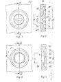
- Fig. 1 eine Aufsicht auf einen Teilbereich eines erfindungsgemäß ausgebildeten Gehäuseteiles,
- Fig. 2 eine Schnittansicht gem. der Linie II-II,
- Fig. 3 eine Aufsicht auf ein Gehäuse mit einer zweiten erfindungsgemäßen Ausgestaltung der Vormarkierungen,
- Fig. 4 eine Schnittansicht gem. der Linie IV-IV der Fig. 3.
- 1 is a plan view of a portion of a housing part designed according to the invention,
- Fig. 2 is a sectional view. line II-II,
- 3 is a plan view of a housing with a second embodiment of the pre-markings according to the invention,
- Fig. 4 is a sectional view. the line IV-IV of Fig. 3rd
Es sei nun Bezug genommen auf die Fig. 1 und 2.Reference is now made to FIGS. 1 and 2.
Die Gehäusewand 10 eines handelsüblichen Leitungsschutzschalters, dessen Einzelheiten nicht näher dargestellt sind, da sie für die Erfindung nicht von Bedeutung sind, besitzt auf der Außenfläche 12 eine erste Vormarkierung 14, der eine zweite Vormarkierung 16 auf der Innenfläche 18 des Gehäuses 10 zugeordnet ist.The
Die als Vertiefung ausgebildete erste Vormarkierung 14 ist außen durch eine kegelstumpfförmig sich erweiternde Ringfläche mit einem an der Außenfläche 12 gemessenen Außendurchmesser D1 und innen durch eine zylindrische Ringfläche mit dem Innendurchmesser DA begrenzt, wogegen die ebenfalls als Vertiefung ausgebildete zweite Vormarkierung 16 außen durch eine zylindrische Ringfläche mit dem Innendurchmesser Di und innen durch eine kegelstumpfförmig sich nach außen verjüngende Ringfläche mit einem an der Innenfläche 18 gemessenen Innendurchmesser D2 begrenzt ist. Beide Vormarkierungen 14 und 16 sind so tief eingeprägt, daß noch in Form einer die beiden Vormarkierungen verbindenden Ringfläche 20 Restmaterial stehenbleibt. Erfindungsgemäß ist der Außendurchmesser Di der Vormarkierung 16 kleiner als der Innendurchmesser D a der Vertiefung 14, so daß die Ringfläche 20 sich kegelstumpfartig nach außen zur Außenfläche 12 hin erweitert. Die Ringfläche 20 ist die kürzeste Verbindungsfläche zwischen den Konturlinien der beiden Vertiefungen.The first pre-marking 14, which is designed as a recess, is delimited on the outside by an annular surface which widens in the shape of a truncated cone and has an outer diameter D 1 measured on the
Im Inneren des Durchmessers DA ist ein Schlitz 22 vorgesehen, der einen Schraubendreher aufnimmt, so daß das durch die Vorsprünge 14 und 16 gebildete Wandteil 24 verdreht und entlang der Ringfläche 20 aus der Wand 10 herausgebrochen werden kann. Die Ringfläche 20 bildet somit eine Art Sollbruchstelle, entlang derer das Wandteil 24 zur Bildung eines Durchbruches herausgebrochen werden kann. Der Durchbruch, der dadurch gebildet wird, wird begrenzt durch die Außenfläche der Vertiefung 16, die senkrecht zur Fläche 18 des Gehäusewandteiles 10 verläuft, die kegelstumpfartige Ringfläche 20 und die Außenfläche der Vertiefung 14. Man erkennt aus der Fig. 2, daß der Außendurchmesser des herausgebrochenen Wandteiles 24 größer ist als der Innendurchmesser, also hier der kleinste Innendurchmesser des Durchbruches, so daß mit Sicherheit vermieden ist, daß das Wandteil 24 ins Innere des Gehäuses, also auf die linke Seite des Gehäuses 10 bzw. der Gehäusewand 10 hineinfällt. Das Wandteil 24 wird grundsätzlich außerhalb des Gehäuses 10 verbleiben.In the interior of the diameter D A , a
Wie oben erwähnt, erfolgt die Verdrehung des Wandteiles 24 mittels eines Schraubendrehers, der in den Schlitz 22 eingesteckt werden kann. In der Ausgestaltung gem. den Fig. 3 und 4 ist das herauszubrechende Wandteil 30 durch eine als Vertiefung ausgebildete Vormarkierung 32 gebildet, deren innere Kontur 34 die Form eines Sechsecks aufweist. Die auf der gegenüberliegenden Seite liegende Vormarkierung ist einfach durch eine kreisförmige Einprägung 36 gebildt, deren Tiefe T1 so gewählt ist, daß die Bodenfläche 38 jenseits der inneren parallel zur Außenfläche 12 verlaufenden Ringfläche 40 (Boden 40) der Vormarkierung liegt, so daß ein Ringbereich 42 kleinster Abmessung gebildet wird, der dann als Sollbruchstelle dient, ein Ringbereich also zwischen der inneren Kontur 34 und dem Boden 40 und der tiefsten Stelle der Vormarkierung 36. Die Verdrehung des Wandteiles 30 erfolgt mittels eines Sechskantsteckschlüssels oder ggf. eines Sechskantringschlüssels. Man erkennt, daß die Schlüsselweite S des Wandteils 30 oder der Durchmesser des äußersten Kreises, der die Kontur 34 umgibt und gleich Da ist, größer ist als der Durchmesser DI der Vertiefung 36, so daß auch hierdurch ein Hineinfallen des ausgebrochenen Wandteiles 30 ins Innere des Gehäuses verhindert ist.As mentioned above, the
Durch die erfindungsgemäße Ausbildung der Gehäusewände an den betreffenden Stellen wird also erreicht, daß sich die Teilstücke 24 und 30 aus der Wand herausbrechen lassen, ohne daß Bruchstücke in das Schalterinnere gelangen können.The inventive design of the housing walls at the relevant points ensures that the
Entlang der Sollbruchstelle, die durch die Ringflächen 20 bzw. 42 gebildet ist, läßt sich durch Verdrehen das Wandteil 24 bzw. 30 herausbrechen, wobei die Abmessungen des herausgebrochenen Teiles, also der Wandteile 24 bzw. 30, größer sind als der lichte Durchmesser des nach dem Herausbrechen des Wandteiles 24 bzw. 30 verbliebenen Durchbruches.Along the predetermined breaking point, which is formed by the
Die Erzeugung der Vormarkierung erfolgt bei der Herstellung, also dem Spritzpressen des Gehäuses bzw. der Gehäuseschale. Es besteht weiterhin auch die Möglichkeit, die Ausgestaltungen gem. den Fig. 1 und 2 bzw. 3 und 4 zu kombinieren, d. h. also, den Schlitz 22 bei einer Sechskantkontur 34 vorzusehen und die Vorprägung 16 nicht so wie in Fig. 2 dargestellt, also keilförmig, sondern mittels einer Vertiefung ähnlich der der Fig. 4 zu bilden.The pre-marking is generated during manufacture, that is to say the injection molding of the housing or the housing shell. There is also the possibility of the configurations according to. 1 and 2 or 3 and 4 to combine, d. H. that is, to provide the
Claims (8)
Priority Applications (1)
| Application Number | Priority Date | Filing Date | Title |
|---|---|---|---|
| AT83102880T ATE31128T1 (en) | 1982-04-01 | 1983-03-23 | HOUSING FOR AN ELECTRICAL INSTALLATION DEVICE. |
Applications Claiming Priority (2)
| Application Number | Priority Date | Filing Date | Title |
|---|---|---|---|
| DE19823212064 DE3212064A1 (en) | 1982-04-01 | 1982-04-01 | HOUSING FOR AN ELECTRICAL INSTALLATION DEVICE |
| DE3212064 | 1982-04-01 |
Publications (3)
| Publication Number | Publication Date |
|---|---|
| EP0091012A2 true EP0091012A2 (en) | 1983-10-12 |
| EP0091012A3 EP0091012A3 (en) | 1986-11-05 |
| EP0091012B1 EP0091012B1 (en) | 1987-11-25 |
Family
ID=6159928
Family Applications (1)
| Application Number | Title | Priority Date | Filing Date |
|---|---|---|---|
| EP83102880A Expired EP0091012B1 (en) | 1982-04-01 | 1983-03-23 | Housing for an electrical installation device |
Country Status (7)
| Country | Link |
|---|---|
| EP (1) | EP0091012B1 (en) |
| AT (1) | ATE31128T1 (en) |
| DE (1) | DE3212064A1 (en) |
| ES (1) | ES271250Y (en) |
| GB (1) | GB2118779B (en) |
| PT (1) | PT76478B (en) |
| ZA (1) | ZA831812B (en) |
Cited By (2)
| Publication number | Priority date | Publication date | Assignee | Title |
|---|---|---|---|---|
| WO2013107485A1 (en) * | 2011-12-20 | 2013-07-25 | Abb Ag | Pre-stamped flange folded portion, component or housing part having such a flange folded portion, switchgear or distribution cabinet having such a component or housing part, and system and method for pre-stamping flange folded portions |
| EP2360800A3 (en) * | 2010-02-12 | 2013-08-28 | Kaiser GmbH & Co. KG | Installation part |
Families Citing this family (3)
| Publication number | Priority date | Publication date | Assignee | Title |
|---|---|---|---|---|
| DE19913816A1 (en) * | 1999-03-26 | 2000-09-28 | Abb Patent Gmbh | Residual current circuit breaker |
| JP6369982B2 (en) * | 2014-07-22 | 2018-08-08 | ホシザキ株式会社 | Opening / closing door support device, opening / closing door assembly method, and pin holder |
| DE102015103900A1 (en) | 2015-03-17 | 2016-09-22 | Abb Ag | Housing for an electrical installation device |
Citations (2)
| Publication number | Priority date | Publication date | Assignee | Title |
|---|---|---|---|---|
| GB773193A (en) * | 1955-09-30 | 1957-04-24 | Chilton Aircraft Company Ltd | Improvements in and relating to electrical circuit-breakers |
| US3069517A (en) * | 1958-04-23 | 1962-12-18 | Fed Pacific Electric Co | Circuit breakers |
Family Cites Families (2)
| Publication number | Priority date | Publication date | Assignee | Title |
|---|---|---|---|---|
| DE1513584B2 (en) * | 1965-07-02 | 1970-05-21 | Stotz-Kontakt GmbH, 6800 Mannheim-Käfertal | Multipole circuit breaker |
| DE7005827U (en) * | 1970-02-19 | 1970-05-21 | Bbc Brown Boveri & Cie | SELF SWITCH WITH INSULATED HOUSING. |
-
1982
- 1982-04-01 DE DE19823212064 patent/DE3212064A1/en not_active Withdrawn
-
1983
- 1983-03-16 ZA ZA831812A patent/ZA831812B/en unknown
- 1983-03-23 EP EP83102880A patent/EP0091012B1/en not_active Expired
- 1983-03-23 AT AT83102880T patent/ATE31128T1/en not_active IP Right Cessation
- 1983-03-30 PT PT76478A patent/PT76478B/en unknown
- 1983-03-30 ES ES1983271250U patent/ES271250Y/en not_active Expired
- 1983-03-31 GB GB08308916A patent/GB2118779B/en not_active Expired
Patent Citations (2)
| Publication number | Priority date | Publication date | Assignee | Title |
|---|---|---|---|---|
| GB773193A (en) * | 1955-09-30 | 1957-04-24 | Chilton Aircraft Company Ltd | Improvements in and relating to electrical circuit-breakers |
| US3069517A (en) * | 1958-04-23 | 1962-12-18 | Fed Pacific Electric Co | Circuit breakers |
Cited By (2)
| Publication number | Priority date | Publication date | Assignee | Title |
|---|---|---|---|---|
| EP2360800A3 (en) * | 2010-02-12 | 2013-08-28 | Kaiser GmbH & Co. KG | Installation part |
| WO2013107485A1 (en) * | 2011-12-20 | 2013-07-25 | Abb Ag | Pre-stamped flange folded portion, component or housing part having such a flange folded portion, switchgear or distribution cabinet having such a component or housing part, and system and method for pre-stamping flange folded portions |
Also Published As
| Publication number | Publication date |
|---|---|
| PT76478A (en) | 1983-04-01 |
| EP0091012B1 (en) | 1987-11-25 |
| ZA831812B (en) | 1984-02-29 |
| ES271250Y (en) | 1984-03-16 |
| GB2118779A (en) | 1983-11-02 |
| DE3212064A1 (en) | 1983-10-06 |
| EP0091012A3 (en) | 1986-11-05 |
| GB8308916D0 (en) | 1983-05-11 |
| GB2118779B (en) | 1985-09-04 |
| ATE31128T1 (en) | 1987-12-15 |
| ES271250U (en) | 1983-08-16 |
| PT76478B (en) | 1985-12-20 |
Similar Documents
| Publication | Publication Date | Title |
|---|---|---|
| WO2001008180A1 (en) | Fuse combination unit with maintained locking | |
| EP0091012B1 (en) | Housing for an electrical installation device | |
| DE2052040C3 (en) | Flameproof fuse | |
| EP1741117B1 (en) | Switchgear | |
| EP0221839A2 (en) | Power switch with a frontal opening of an insulative enclosure and a circuit board | |
| EP0180008B1 (en) | Fuse element | |
| DE3807191A1 (en) | SCREW CONNECTOR FOR ELECTRICAL LADDERS | |
| EP0059939A1 (en) | Terminal for the connection of electrical conductors | |
| EP0703641A2 (en) | Electrical connection member | |
| DE102004042427A1 (en) | Electrical installation device | |
| DE3323861C2 (en) | ||
| DE10061564B4 (en) | Connection unit for multi-pole switch | |
| DE2322372A1 (en) | MULTIPOLE VACUUM SWITCHING DEVICE | |
| DE112017007241B4 (en) | TRIGGER SWITCH | |
| DE69834897T2 (en) | Confusion protection arrangement for electrical switching devices, in particular for circuit breakers and residual current circuit breakers | |
| DE3220840C2 (en) | Flameproof, explosion-proof electrical switching device | |
| EP0204905A2 (en) | Automatic circuit breaker | |
| DE60302376T2 (en) | breaker | |
| DE19627971C2 (en) | BNC connector | |
| DE19734234C2 (en) | Securing with coding | |
| DE19842878C1 (en) | Circuit breaker with encoding for circuit protection, has adjustable encoding insert with openings of different depths for accommodating encoding tongue depending on rated current | |
| DE69020763T2 (en) | Gripping device and holder for handling a tubular fuse. | |
| DE3248683C2 (en) | ||
| EP1002326B1 (en) | Fuse with coding | |
| DE29714132U1 (en) | Automatic coding protection |
Legal Events
| Date | Code | Title | Description |
|---|---|---|---|
| PUAI | Public reference made under article 153(3) epc to a published international application that has entered the european phase |
Free format text: ORIGINAL CODE: 0009012 |
|
| AK | Designated contracting states |
Designated state(s): AT BE CH FR IT LI NL |
|
| PUAL | Search report despatched |
Free format text: ORIGINAL CODE: 0009013 |
|
| AK | Designated contracting states |
Kind code of ref document: A3 Designated state(s): AT BE CH FR IT LI NL |
|
| 17P | Request for examination filed |
Effective date: 19861211 |
|
| 17Q | First examination report despatched |
Effective date: 19870407 |
|
| GRAA | (expected) grant |
Free format text: ORIGINAL CODE: 0009210 |
|
| AK | Designated contracting states |
Kind code of ref document: B1 Designated state(s): AT BE CH FR IT LI NL |
|
| REF | Corresponds to: |
Ref document number: 31128 Country of ref document: AT Date of ref document: 19871215 Kind code of ref document: T |
|
| ITF | It: translation for a ep patent filed | ||
| ET | Fr: translation filed | ||
| PLBE | No opposition filed within time limit |
Free format text: ORIGINAL CODE: 0009261 |
|
| STAA | Information on the status of an ep patent application or granted ep patent |
Free format text: STATUS: NO OPPOSITION FILED WITHIN TIME LIMIT |
|
| 26N | No opposition filed | ||
| PG25 | Lapsed in a contracting state [announced via postgrant information from national office to epo] |
Ref country code: AT Effective date: 19890323 |
|
| PG25 | Lapsed in a contracting state [announced via postgrant information from national office to epo] |
Ref country code: LI Effective date: 19890331 Ref country code: CH Effective date: 19890331 Ref country code: BE Effective date: 19890331 |
|
| BERE | Be: lapsed |
Owner name: BOVERI & CIE A.G. Effective date: 19890331 Owner name: BROWN Effective date: 19890331 |
|
| PG25 | Lapsed in a contracting state [announced via postgrant information from national office to epo] |
Ref country code: NL Effective date: 19891001 |
|
| NLV4 | Nl: lapsed or anulled due to non-payment of the annual fee | ||
| PG25 | Lapsed in a contracting state [announced via postgrant information from national office to epo] |
Ref country code: FR Free format text: LAPSE BECAUSE OF NON-PAYMENT OF DUE FEES Effective date: 19891130 |
|
| REG | Reference to a national code |
Ref country code: CH Ref legal event code: PL |
|
| REG | Reference to a national code |
Ref country code: FR Ref legal event code: ST |