EP0090004B1 - Systeme de purification de liquides - Google Patents
Systeme de purification de liquides Download PDFInfo
- Publication number
- EP0090004B1 EP0090004B1 EP82903023A EP82903023A EP0090004B1 EP 0090004 B1 EP0090004 B1 EP 0090004B1 EP 82903023 A EP82903023 A EP 82903023A EP 82903023 A EP82903023 A EP 82903023A EP 0090004 B1 EP0090004 B1 EP 0090004B1
- Authority
- EP
- European Patent Office
- Prior art keywords
- liquid
- vapor
- evaporator
- vessel
- heat exchanger
- Prior art date
- Legal status (The legal status is an assumption and is not a legal conclusion. Google has not performed a legal analysis and makes no representation as to the accuracy of the status listed.)
- Expired
Links
Images


Classifications
-
- C—CHEMISTRY; METALLURGY
- C02—TREATMENT OF WATER, WASTE WATER, SEWAGE, OR SLUDGE
- C02F—TREATMENT OF WATER, WASTE WATER, SEWAGE, OR SLUDGE
- C02F1/00—Treatment of water, waste water, or sewage
- C02F1/02—Treatment of water, waste water, or sewage by heating
- C02F1/04—Treatment of water, waste water, or sewage by heating by distillation or evaporation
-
- B—PERFORMING OPERATIONS; TRANSPORTING
- B01—PHYSICAL OR CHEMICAL PROCESSES OR APPARATUS IN GENERAL
- B01D—SEPARATION
- B01D9/00—Crystallisation
- B01D9/02—Crystallisation from solutions
- B01D9/04—Crystallisation from solutions concentrating solutions by removing frozen solvent therefrom
-
- C—CHEMISTRY; METALLURGY
- C02—TREATMENT OF WATER, WASTE WATER, SEWAGE, OR SLUDGE
- C02F—TREATMENT OF WATER, WASTE WATER, SEWAGE, OR SLUDGE
- C02F1/00—Treatment of water, waste water, or sewage
- C02F1/22—Treatment of water, waste water, or sewage by freezing
-
- C—CHEMISTRY; METALLURGY
- C02—TREATMENT OF WATER, WASTE WATER, SEWAGE, OR SLUDGE
- C02F—TREATMENT OF WATER, WASTE WATER, SEWAGE, OR SLUDGE
- C02F2103/00—Nature of the water, waste water, sewage or sludge to be treated
- C02F2103/08—Seawater, e.g. for desalination
-
- Y—GENERAL TAGGING OF NEW TECHNOLOGICAL DEVELOPMENTS; GENERAL TAGGING OF CROSS-SECTIONAL TECHNOLOGIES SPANNING OVER SEVERAL SECTIONS OF THE IPC; TECHNICAL SUBJECTS COVERED BY FORMER USPC CROSS-REFERENCE ART COLLECTIONS [XRACs] AND DIGESTS
- Y02—TECHNOLOGIES OR APPLICATIONS FOR MITIGATION OR ADAPTATION AGAINST CLIMATE CHANGE
- Y02A—TECHNOLOGIES FOR ADAPTATION TO CLIMATE CHANGE
- Y02A20/00—Water conservation; Efficient water supply; Efficient water use
- Y02A20/124—Water desalination
-
- Y—GENERAL TAGGING OF NEW TECHNOLOGICAL DEVELOPMENTS; GENERAL TAGGING OF CROSS-SECTIONAL TECHNOLOGIES SPANNING OVER SEVERAL SECTIONS OF THE IPC; TECHNICAL SUBJECTS COVERED BY FORMER USPC CROSS-REFERENCE ART COLLECTIONS [XRACs] AND DIGESTS
- Y02—TECHNOLOGIES OR APPLICATIONS FOR MITIGATION OR ADAPTATION AGAINST CLIMATE CHANGE
- Y02W—CLIMATE CHANGE MITIGATION TECHNOLOGIES RELATED TO WASTEWATER TREATMENT OR WASTE MANAGEMENT
- Y02W10/00—Technologies for wastewater treatment
- Y02W10/30—Wastewater or sewage treatment systems using renewable energies
- Y02W10/37—Wastewater or sewage treatment systems using renewable energies using solar energy
-
- Y—GENERAL TAGGING OF NEW TECHNOLOGICAL DEVELOPMENTS; GENERAL TAGGING OF CROSS-SECTIONAL TECHNOLOGIES SPANNING OVER SEVERAL SECTIONS OF THE IPC; TECHNICAL SUBJECTS COVERED BY FORMER USPC CROSS-REFERENCE ART COLLECTIONS [XRACs] AND DIGESTS
- Y10—TECHNICAL SUBJECTS COVERED BY FORMER USPC
- Y10S—TECHNICAL SUBJECTS COVERED BY FORMER USPC CROSS-REFERENCE ART COLLECTIONS [XRACs] AND DIGESTS
- Y10S203/00—Distillation: processes, separatory
- Y10S203/18—Control
Definitions
- This invention relates to a liquid purification system, for separating an impurity from a liquid and, more particularly, to the separation of the solvent and solute of a solution by an induced phase change.
- the invention also relates to a process, using the system aforementioned.
- distillation process is objectionable due to problems of high corrosion and high energy consumption.
- the solution is to be heated and there are problems of heat recovery so as to minimize the running costs. This is particularly true in the case of corrosive brine or brackish water solutions which require pretreatment, special materials and utmost care.
- EP-A-0 015 157 discloses a freeze-drying process for separating water from aqueous solutions and comprises a vacuum-freezing step, an ice-washing step, a simultaneous vapor desubli- mation and high pressure ice-melting step and, eventually, a simultaneous desublimate dissolution and exchange ice-formation step.
- the temperature of triple point of a saline solution is lowered progressively from that of pure water with increasing concentration of the ions of a dissolved salt.
- the invention therefore, provides a liquid purification system, comprising a chamber for supplying a liquid containing dissolved impurities to an evaporator, a passageway for conveying said liquid from said chamber to said evaporator, an evacuating device operatively connected to said evaporator for inducting the simultaneous coexistence of vapor and liquid and/or solid phases of said impure liquid in said evaporator, wherein said vapor phase formed by spontaneous vaporization is essentially free of impurities, and removes heat from said impure liquid to thereby reduce the temperature of the liquid and/ or solid phases thereof, characterized by additionally comprising: a heat exchanger which is connected to said evaporator for receiving the liquid and/or solid phases of said impure liquid, and a vessel closed and about said evaporator and said heat-exchanger for receiving and conveying the vapor from said evaporator to said heat-exchange surface for condensation of said vapor as the heat from the vapor is transferred to said heat-exchanger and as the liquid and/or solid
- Another aspect of the invention is a process for purifying liquid comprising the steps of: inducing a phase change in a first liquid containing dissolved impurities in an evaporator wherein said phase change includes the spontaneous formation of the vapor phase essentially free of said impurities, wherein said vapor phase co-exists with said liquid and/or solid phase of said first liquid in said evaporator and said vapor phase removes heat from said first liquid and thereby reduces the temperature thereof, maintaining a second liquid within a heat exchanger which is the same as said first liquid but with a greater concentration of said impurities and at a lower temperature, conveying the solid and/or liquid phases of said first liquid to and within said heat exchanger, and conveying said vapor through a vessel into thermal contact with said heat exchanger to condense said vapor to liquid essentially free of impurities as the heat from said vapor is transferred to said second liquid and as the solid and/or liquid phases of said first liquid cools said second liquid within said heat exchanger.
- the separation of the liquid from its impurity is accomplished by a process of induced phase change wherein a portion of the liquid spontaneously vaporizes, thereby removing heat from the remaining liquid and impurities which are allowed to be separated from the vapor.
- the remaining liquid has a much higher concentration of dissolved impurity and, upon the removal of the heat, becomes supercooled and releases pure solid ice leaving a mixture of concentrated brine and ice crystals.
- the phase change is accomplished by a sudden reduction in pressure as may be attained by passing the impure liquid from a region of higher pressure to a region of lower pressure.
- the supercooled liquid is at a lower temperature than the vapor and, therefore, may be advantageously utilized within a heat exchanger for condensing the vapor to pure liquid.
- the mixture of ice and liquid can be blended with an even more concentrated impure liquid, thus causing the ice to melt and the temperature of the blend to lower below that of the vapor, this blend being advantageously utilized within a heat exchanger for condensing the vapor to pure liquid.
- An exemplary embodiment of the system of the invention comprises a plurality of operatively interacting and interconnected chambers or vessels for performing the foregoing process.
- the first chamber is at a higher pressure than the other chambers.
- the first chamber would be at atmospheric pressure, and the other chambers would have a pressure of 100-odd Pascal.
- the first and second of the chambers provide the foregoing regions of higher and lower pressure, the impure liquid passing from the first chamber to the second chamber via an interconnecting orifice or passageway.
- the second chamber communicates with a third chamber via an open top of the second chamber, and the second chamber communicates with a fourth chamber via an interconnecting orifice or passageway.
- the fourth chamber contains concentrated brine at a temperature below the triple point for the impure feed solution.
- the fourth chamber is constructed within the third chamber so that the cold outside walls of the fourth chamber can be used for condensing vapor within the third chamber.
- the impure feed solution in the first or supply chamber at the higher pressure drips into the second or vaporization chamber at the lower pressure via the interconnecting orifice.
- This sudden change in pressure induces phase changes in the impure feed solution.
- Pure vapor is formed and drawn into the third or condensing chamber, and condenses on the outside walls of the fourth or heat exchange chamber.
- the common walls between the third and fourth chambers act as a heat exchanger and are cooled by the precooled concentrated solution inside the fourth chamber to a temperature sufficiently low to cause condensation of the vapor.
- the impure feed solution, having lost pure vapor and heat, is now either a supercooled impure liquid or a mixture of concentrated impure liquid and pure solid solvent crystals.
- Either the supercooled liquid or the mixture of impure liquid and pure solids passes into the fourth chamber via the interconnecting orifice, and mixes with the cold concentrated solution already in the fourth chamber, thereby lowering its temperature.
- the heat given up to the concentrated solution in the fourth chamber by the condensing vapor in the third chamber is transferred to the supercooled liquid or the mixture of impure liquid and pure solids, and thereby restores the original concentrated solution in the fourth chamber to its original temperature.
- the invention provides several major advantages.
- the process utilized by the system is substantially independent of the nature of the feed solutions which are to be purified and, furthermore, des not require any special pretreatment of the feed solution. Since the system operates at ambient temperatures and at lower temperatures no energy is consumed in heating the feed and, plastic materials can be used extensively within the system to substantially eliminate corrosion and fouling. Moreover, since the system is under a high vacuum, little air is present so that the combination of low temperature and low oxygen levels substantially decreases corrosion on metals when used. Also, since the process does not require the use of pretreatment chemicals, the use of the system is free of the dangers of environmental pollution associated with the use of such chemicals.
- the system operates at temperatures extending below zero centigrade, to typically -19°C., and at pressures near zero millimeters of mercury. At such low temperature, an opportunity is provided which allows metal to be used for the system, since negligible corrosion occurs as would occur in the high temperature operation of boiling water at standard or elevated pressures. Also, the relatively low temperature permits the use of plastic materials in construction for major components of the system.
- the pressure is up to about 399,6 Pa (3 mm of mercury), typically from about 13,33 Pa (0.1 mm Hg) to 399,6 Pa (3.0 mm) of mercury. It has been found that highly desirable results are achieved from 199,98 Pa (1.5 mmHg) to 333,3 Pa (2.5 mm of mercury).
- a conduit such as a pipe
- a constriction in the conduit, or a suitable valve or pump connected to the conduit meters the rate of flow of the impure liquid into the second chamber, the output of such metering device serving as the aforementioned interconnecting orifice.
- the incoming impure liquid from the reservoir can be premixed in a predetermined ratio with the foregoing concentrated solution prior to presenting the impure liquid at the orifice.
- the mixing aids in reducing the temperature of the incoming impure liquid and allows reprocessing of previously processed impure liquid for further concentration of and extraction of product.
- the lower temperature feed makes the process more economical by reducing the amount of excess vapor above that required for equilibrium.
- the supercooled liquid can be produced by vaporization of a portion of the liquid from thin films thereof on a set of plates located inside the second chamber.
- ice can be obtained by running the saltwater feed mixture down the side walls of the second chamber. In both instances the amount of heat added to the vapor is about equal to the amount of heat removed from the concentrated brine.
- the supercooled liquid drains into the fourth chamber it absorbs the heat of the condensing vapor. In the case where ice is formed the ice tends to drive the concentrated salt solution to the freezing point, and in doing so, absorbs the heat of the condensing vapor.
- auxiliary cooling units and vacuum pumps are provided for initially establishing the operating temperatures and pressures.
- the cooling units and vacuum pumps can be used intermittently during normal operation if required, such as to compensate for air and thermal leaks.
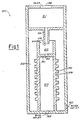
- FIG. 1 is a simplified schematic diagram of the basic components of the liquid purification system made in accordance with the invention.
- FIG. 1 there is shown a schematic representation of a system 20 of the invention for the desalination of sea water.
- Salts primarily sodium chloride, constitute the impurities which are to be removed from the sea water.
- the system 20 provides for the induced phase change of the sea water converting part of it from the liquid phase to the vapor phase.
- the vapor is free of impurities, and is subsequently condensed to pure water.
- the system 20 includes four chamber forming vessels 21-24.
- the vessel 21 is above vessel 23 and vessels 22 and 24 are within the closed vessel 23 in a superimposed relationship.
- the pressure in vessel 21 is atmospheric and in vessels 22-24 slightly below the triple point for the sea water and brine feed solution.
- the operation of the system 20 is initiated by filling the fourth or heat exchange vessel 24 with a cold concentrated brine solution near its freezing point and below the saturation temperature of the system.
- the sea water feed enters the second or vaporization vessel 22 through a conduit forming orifice 28 under the driving force produced by the difference in pressure between the two vessels 21-22.
- the conduit forming orifice 28 is open to and depends from the vessel 21, and, because of its relatively small size, the orifice 28 meters the flow of sea water feed mixture into the second vessel 22 at a predetermined rate.
- the condenser walls which can be finned or ribbed to increase surface area, form a physical barrier preventing the condensing pure water from uniting with the residual brine and ice mixture to be described, but allowing heat to be transferred from the vapor to melt the ice.
- Residual brine and pure ice mixture containing the impurities enters vessel 24 through aperture 32 and is intimately mixed with the aforesaid concentrated brine already contained in the vesse! ' 24. Because of the high salt content of this mixture, its freezing point is below the saturation temperature of the vapor. Heat transferred from the vapor to the brine ice mixture in the vessel 24 via the exchanger walls 29 will melt the ice contained therein maintaining the temperature differential required for condensation.
- a condenser 36 is formed of a set of tubes 42 depending from the vessel 24 and about which the water vapor circulates.
- Cold brine passes from the vessel 24 through the tubes 42 to chill the condenser 36 and remove the heat of vaporization from the water vapor to condense the vapor to liquid water.
- the lower end of the set of tubes 42 terminates at an opens into a chamber 44 within vessel 23 and in which the brine is collected and recirculated via conduits 47-48 and pump 50.
- the pump forces the brine via the conduit 47-48 from the chamber 44 back into the vessel 24 for recirculation of the brine.
- An outlet 52 at the pump 50 permits withdrawal of surplus amounts of the brine.
- a partial vacuum is drawn on the vessels 22-24 by a vacuum pump 54 coupled via a conduit 56 to the vessel 23 under control of a pressure sensor 58 coupled between the conduit 56 and the pump 54.
- the pressure in the vessel 23 is preferably up to 399,6 Pa (3.0 mm of mercury), e.g., from 13,33 Pa (0.1 mmHg) to 399,6 Pa (3.00 mm of mercury). Typical preferred pressures are from about 1.5 mm to about 2.5 mm of mercury.
- the conduit or passage 26 takes the form of a length of pipe of sufficiently small diameter to produce viscous drag to the flow of the impure or brackish water, the flow being indicated by an arrow 62. Due to the viscous drag, a back pressure builds up along the passage 26 which counterbalances the difference in pressure between the first vessel 21 and the other vessels 22-24. Equilibrium in the rate of flow of the fluid is established when the flow rate is sufficiently high to provide the compensating back pressure.
- the temperature of the solution begins to drop and reaches its saturation temperature as determined by the pressure in the vessel 22. This temperature should be lower than the triple point temperature of the sea water feed mixture.
- the pure vapor, ice, and brine all co-exist at a temperature determined by the pressure.
- the coldest temperature is found in the brine in the condenser 36 after passing through a temperature differential mechanism 64.
- the condenser temperature must be below that of the saturation temperature in vessel 23.
- the sea water feed spontaneously establishes pure vapor, liquid brine, and ice all at the saturation temperature.
- the vapor escapes primarily through the opening 34 while a small amount of vapor escapes via aperture 32.
- the vapor escaping via the upper opening 34 condenses on the outside surfaces of the condenser tubes 42 while the vapor escaping via the lower aperture 32 condenses on the surface of the water in the vessel 24.
- the temperature differential mechanism 64 is included within the system 20 for lowering the temperature of the liquid within the vessel 24to insure the condensation of the vapor in the vessel 23 upon the tubes 42 through which the liquid passes.
- Different forms of such a mechanism will be described in Figures 3-6.
- the mechanism may be implemented by means of chemical, physical or mechanical processes.
- the chemical process is referred to as freezing point depression which may be explained as follows.
- the addition of salts or other impurities to a liquid causes its freezing point to be depressed.
- the freezing point of pure water is 0°C; however, in a saturated solution of sodium chloride, the freezing point is depressed to -20°C. If ice at 0°C is added to this saturated salt solution, the ice will melt until ice and saturated salt solution are in equilibrium at -20°C. This phenomenon can be used as a temperature differential mechanism. Referring to Figure 2, when the sea water feed mixture enters vessel 22, vapor, ice, and brine are formed all at the saturation temperature.
- the brine in vessel 24 is more concentrated than the feed, the brine has a lower freezing point, is cooler than the saturation temperature established, and will remain a liquid.
- the ice generated in vessel 22 from the sea water feed mixture passes through aperture 32 and is blended with the concentrated brine in vessel 24, it serves to hold the brine in vessel 24 at its freezing point by melting as heat is added by the vapor condensing on the tubes 42.
- the supercooling phenomenon is found under suitable conditions such as the presence of fine sprays or thin films wherein liquids can cool below their normal freezing points.
- water having a normal freezing point of 0°C can exist as a liquid at temperatures as low as -40°C.
- the supercooling process is to be applied to feed water entering the vessel 22.
- the resulting reduction in temperature of the feedwater and its addition to the circulating body of residual liquid in the vessel 24 serves as the temperature differential mechanism 64.
- a solar panel or pond may be used to raise the temperature of the feed water significantly. It is then possible to set the pressure such that spontaneous separation of the vapor occurs between the temperature of the incoming feed mixture and that of the surrounding atmosphere. Under these conditions a heat exchanger can be used as the temperature differential mechanism 64 and used to transfer heat to the atmospheric air or large body of water as will be described with reference to Figure 5.
- a heat transfer coil may be inserted within the chamber 44. A coolant from a mechanical refrigerator or thermoelectric cooling device would then be circulated through the transfer coil to cool down the residual liquid to serve as the temperature differential mechanism 64.
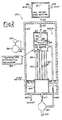
- FIG. 3 there is shown a system 20A for liquid purification utilizing the process of freezing point depression, the system 20A being obtained by modifying the system 20 of Figure 2 to accommodate the freezing point depression.
- the system 20A comprises the vessels 21-24, the condenser 36, and the pumps 50 and 54 which were described in Figure 2.
- the system 20A further comprises a feed valve 66, a recirculation valve 68, a wash valve 70, a freeze valve 72, a defrost valve 74 and a drain valve 76.
- Two pressure sensors 58A-B are coupled via a selector switch 78 to the pump 54 for providing two pressure states within the vessels 22-24.
- a timer 80 provides timing signals at terminals T1T5 for controlling respectively the operation of the valves 68, 70, 72, 74 and the switch 78 to which they are connected in a conventional manner.
- the outlet 40 is coupled by an optional drain pump 82 and pipe 84 to the bottom of the third vessel for pumping out the purified water.
- the body of residual liquid is drawn off the bottom of the chamber 44 for recirculation by intake pipe 86 and pump 50.
- Initial cool-down of the liquid in the system 20A is obtained by a chiller 88 coupled to a cooling coil 90 set within the chamber 44.
- the chiller 88 is operated in response to a sensing of the liquid temperature by a temperature sensor 92.
- the recirculating liquid is concentrated brine which is cooled down by the chiller 88 to a temperature of approximately 0°F.
- the output port of the pump 50 is coupled by a conduit system 94 to the valves 68, 70, 72 and 74.
- Conduits 97-98 coupled respectively to the valves 68 and 70, respectively, bring recirculating brine to the vessels 24 and 22 respectively.
- a heat exchanger 100 is coupled in conduit system 94 downstream of the valve 74 for heating the residual liquid by withdrawing heat from the outside atmosphere, which generally is warmer than the residual liquid as will be explained subsequently.
- the valves 72 and 74 are coupled to a second inlet conduit 102 of the vessel 21.
- the orifice 28 ( Figure 2) at the lower terminus of the conduit 26 is in the form of an optional nozzle 28A ( Figure 3).
- a nozzle 104 is provided at the upper end of the conduit 98 for directing recirculating liquid downwardly towards the vessel 24.
- a grid 106 is placed between the barrier 30 and the nozzle 28A in the vessel 22 to assist in the nucleation of ice crystals.
- a mist eliminator 108 is placed beneath the opening 34 in the vessel 22 for removing mist from water vapor exiting via the opening 34 to the vessel 23.
- the mist eliminator 108 is advantageously located between the nozzles 28A and 104 to facilitate the removal of ice from the eliminator 108, as will be described subsequently.
- phase state diagram for water showing the solid, the liquid and the gaseous states as a function of temperature and pressure.
- the phase state diagram for water exhibits the triple point.
- the triple point is dependent on the concentration of the impurity, herein salt, in the water. Since the temperature of the triple point is lowered by the introduction of salt into the water, and drops still further with increasing concentration of the salt, the triple point temperature of the residual liquid in the fourth vessel 24 is lower than that of the liquid in the first vessel 21.
- the relatively dilute solution at the nozzle 28A is held below its triple-point temperature, while, in the fourth vessel 24 the more concentrated solution is held above its triple-point temperature.
- spontaneous vaporization of the liquid occurs with a consequent separation of the impurity from the vapor.
- the vapor passes via the mist eliminator 108 and the opening 34 into the third vessel 23 for condensation at the condenser 36 due to the relatively low temperature of the residual liquid contained therein.
- the dissolving of the impurities in the residual liquid and the melting of the ice in the residual liquid reduce the temperature thereof and, upon passage of the residual liquid from the vessel 24 through the condenser 36, provides the requisite low temperature for condensation of the vapor.
- the dissolving of the impurities and the melting of the ice in the residual liquid provides the function of the temperature differential mechanism 64 of Figure 2.
- the operation of the system 20A involves the following sequence of steps, namely, the initial step of charging the vessels and conduits with an initial quantity of residual liquid with salt dissolved therein, this being followed by a reduction in temperature by the chiller 88 and then a reduction in pressure by the vacuum pump 54.
- the reduction in temperature precedes the reduction in pressure so as to avoid any boiling of the brine.
- the operation of the system 20A continues with a two-step procedure involving the alternating steps of an ice cycle and a defrost cycle.
- the cycles are implemented by operation of respective ones of the valves 68, 70, 72 and 74.
- the implementation of the foregoing steps in the operation of the system 20 will now be explained for the case of sea water as the contaminated liquid, it being understood that other contaminated liquids may be processed by the system 20A.
- the sea water is fed into the vessel 21 via the valve 66 and the inlet 38. Residual liquid is also fed into the vessel 21 via the inlet 102.
- the vessel 21 serves as a mixing chamber for mixing together the feed and residual liquids.
- the pump 50 develops sufficient pressure to force the residual liquid up to the top of the system 20A within the vessel 21 wherein the pressure is approximately at atmospheric pressure.
- an additional pump may be applied at the inlet to the feed valve 66 for pumping in the feed liquid. Since the pressure at the outlet of the pump 50 is above atmospheric pressure, excess residual liquid is readily forced out through the drain valve 76.
- the mixing of the feed and residual liquids in the vessel 21 serves to reduce the temperature of the feed liquid.
- the residual liquid has a temperature of -17.8°C (0°F)
- the sea water feed in a warm climate is at 26.7°C (80°F)
- a mixing of 3 parts of sea water to 5 parts of residual liquid will result in a net temperature of this mixture of -1.11°C (30°F).
- the concentration of typical sea water is approximately 35.8 grams of salt per liter of solution.
- the residual liquid is a saturated salt solution and would have a concentration of 256.1 grams of salt per liter of solution.
- the resulting triple point would be -3.557°C (25.6°F), at a pressure of approximately 1.9 mm of mercury.
- the pressure in vessel 22 be set at 1.5 millimeters of mercury. While the sea water and residual liquid mixture is in vessel 21 the mixture is at 30°F and atmospheric pressure; so it remains in the liquid state. As the liquid advances through the passage 26, the pressure thereof drops to the foregoing value of 1.5 millimeters of mercury. For this mixture, the concentration and the pressure is below the triple point of the mixed liquid at nozzle 28A resulting in the induced phase change of the liquid providing the vapor plus the residual ice crystals and precipitated impurities.
- the residual liquid is circulated through the condenser 36 and the pump 50 via the freeze valve 72.
- the initial charge of the brine solution of the residual liquid has a concentration of 2.14 pounds of sodium chloride per gallon of fresh water.
- the quantity of the initial charge is sufficient to raise the level of residual liquid to approximately the center of the fourth vessel 24; the water level should not rise above the barrier 30.
- further residual liquid is drawn from the chamber 44 via the intake pipe 86fortransmission by the recirculation valve 68 and the pipe 97 indirectly into the fourth vessel 24.
- the valves 66 and 72 are adjusted so as to produce the desired mixing ratio while the valve 68 is maintained fully open so as to insure an adequate flow rate in the recirculation of the residual liquid.
- the crystals adhering to the grid 106 facilitate the nucleation of additional ice in the products of the phase change from the nozzle 28A located directly above the grid 106.
- some ice and brine mixture may splash on the mist eliminator 108, resulting in an accumulation of ice thereon as well as on the grid 106. Since the residual fluid is above its freezing point of -19.16°C (-2.5°F), any buildup of ice is readily converted to liquid; and any vapor condensing on a surface cooled by the residual liquid, such as the outer surfaces of the tubes 42, is condensed to ice.
- the excess ice is periodically washed off of the eliminator 108 and the grid 106.
- the removal of the ice is accomplished by the alternate use of the recirculation valve 68 and the wash valve 70.
- the valve 68 is closed and the valve 70 is opened to direct the residual liquid via the pipe 98 and the nozzle 104 to flow through the mist eliminator 108 and the grid 106 so as to absorb the ice into the residual liquid.
- the drain valve 76 is momentarily opened to permit the pump 50 to force out the excess liquid. Thereby, during the ice cycle, any formation of ice on the eliminator 108 and the grid 106 is periodically washed off.
- the defrost cycle is initiated after a buildup of a predetermined amount of ice on the exterior surfaces of the condenser 36.
- the valves 68 and 72 close, the valve 74 opens, and the selector switch 78 is operated to allow the pressure within the vessels 22-24 to rise between 5 and 6 millimeters of mercury.
- the timer 80 is preset to provide for periodic operation of the valves 68, 72 and 74 and the switch 78 in accordance with the estimated time of buildup of the ice on the surfaces of the condenser 36.
- the flow of residual fluid through the valve 72 ceases and the residual fluid passes via the heat exchanger 100 and valve 74 to the vessel 21.
- the heat exchanger 100 transfers heat from the warmer atmosphere to the recirculating residual liquid to raise the temperature thereof to a value more nearly equal to that of the incoming sea-water feed at the inlet 38.
- the feed valve 66 may be closed during the defrost cycle to terminate the flow of the feed liquid during the defrost cycle.
- the pressure sensors 58A-B are preset at different values of pressure to activate the vacuum pump 54.
- the sensor 58A is set at the aforementioned exemplary value of 1.5 millimeters of mercury while the sensor 58B is set at a value of pressure that is higher by approximately 5 to 6 millimeters of mercury.
- activation of the switch 78 selects either the higher or lower pressure.
- the lower pressure is established during the ice cycle, and the higher pressure is established during the defrost cycle.
- the relatively warm mixed liquid entering the nozzle 28A flashes off into vapor and cold brine.
- the vapor condenses on the ice at the surface of the condenser 36 causing the ice to melt.
- the timer 80 allows sufficient time for most of the ice to melt before reverting to the next ice cycle.
- purified water builds up in the bottom of the vessel 23 and is pumped out by the pump 82 through the outlet 40.
- the timer 80 transmits timing signals via its terminals T1 and T3-T5 to the corresponding valves 68, 72 and 74 and to the switch 78 to reinstitute the ice cycle.
- FIG. 4 there is shown a system 20B which is a further embodiment of the system 20 of Figure 2 for use with the supercooling process to provide the function of the temperature differential meehanism 64 of Figure 2.
- the system 20B includes most of the structural features already described in Figure 3. The construction of the system 20B is most readily described by comparing it to the system 20A of Figure 3.
- the system 20B includes the vessels 21-24, the pump 50, the chiller 88, the pumps 50 and 82, and the heat exchanger 100 previously seen in Figure 3.
- the orifice 28 of Figure 2 includes a - nozzle 28B disposed at the lower end .of the passage 26.
- An opening 34A having inclined sides is disposed at the entrance to the second vessel 22.
- a set of plates 110 is located within the second vessel 22 between the opening 34A and the barrier 30 for receiving thin films of liquid upon which the supercooling phenomenon can take place.
- the conduit 98 providing the washing function and the fluid circulation via the valve 72 of Figure 3 are not included in the system 20B of Figure 4.
- the conduit 97 and the recirculation valve 68 coupled thereto function in the same manner in the system 20B ( Figure 4) and the system 20A ( Figure 3).
- the operation of the system 20B follows that of the system 20A except for an alternative form of the temperature differential mechanism wherein the supercooling process is utilized in the system 20B of Figure 4.
- Residual chilled liquid, the brine recirculates from the chamber 44 via the pump 50 and the conduit 97 to the fourth vessel- 24.
- the incoming feedwater is mixed in the first vessel 21 in a predetermined ratio with the residual liquid conveyed by the heat exchanger 100.
- the heat exchanger 100 transfers heat from the environment to the brine so as to provide the optimal temperature for the mixed liquid in the passage 26 for the supercooling of the mixed liquid upon its deposition on the plates 110.
- Evaporation of the liquid from the plates 110 cools the liquid well below its normal freezing point to a temperature of typically -12.32°C (10°F).
- the degree of supercooling is a function of cooling rate, water particle size or layer thickness, and concentration. Slower cooling, smaller thickness, and increased impurities all increase the amount by which the water can be supercooled.
- Vapor formed upon the evaporation of the liquid from the plates 110 passes through the opening 34A into the vessel 23 whereupon the vapor condenses at the condenser 36 to pure liquid water. The liquid water is then drawn off at the outlet 40.
- FIG. 5 there is shown a system 20C which is another embodiment of the system 20 of Figure 2.
- the system 20C includes the four vessels 21-24, the vacuum pump 54, the recirculation pump 50, the condenser 36 and the heat exchanger 100 previously seen in Figures 3-4.
- the chiller 88 of Figures 3 and 4 is used in the system 20C of Figure 5.
- the system 20C includes an additional heat exchanger 112 to perform the function of the temperature differential mechanism 64 of Figure 2 in lieu of the processes of freezing point depression ( Figure 3) and supercooling (Figure 4).
- the operation of the system 20C follows that of the system 20B of Figure 4 in that a portion of residual liquid is passed through the heat exchanger 100 for mixing in the vessel 21 in a predetermined ratio with the incoming feedwater to provide a mixed liquid in the passage 26.
- the liquid in the passage 26 passes from normal atmospheric pressure in the vessel 21 to a reduced pressure, determined by the operating temperatures of the heat exchangers 100 and 112, in the partial vacuum of the vessel as provided by the vacuum pump 54.
- the heat exchanger 100 were a solar panel delivering impure water at 60°C and heat exchanger 112 was operating at an ambient air temperature of 20°C, then the range of pressures would be from 17 to 149 with atypical value of3,996 kPa (30 millimeters of mercury).
- the induced phase change of the impure liquid exiting the nozzle 28C results in liquid with a higher concentration of impurities and of a lower temperature dropping into the fourth vessel 24 while the resulting pure vapor passes into the vessel 23 to be condensed by the condenser 36 into purified liquid.
- the pump 50 recirculates the residual liquid of the chamber 44 through the heat exchanger 112 to remove whatever heat has been added by the condensing vapor.
- concentrations of the liquids in the embodiment of the system 20C need not necessarily be the same as those utilized in the embodiment of the system 20A since no reliance is made upon the process of freezing point depression wherein solid matter, ice, melts within the liquid, water.
- the system 20C is useful in cold climates wherein the outside temperature may be utilized to withdraw heat from the residual liquid at the heat exchanger 112.
- the heat exchanger 100 assuming the cold environment, should be placed in an environment of relatively warm air for heating the recirculating liquid to a specified temperature for the mixing operation in the vessel 21. If desired, the heat exchanger 100 may be modified to receive solar energy or waste heat from some other industrial process.
- FIG. 6 there is shown a system 20D which is yet a further embodiment of the system 20 of Figure 2.
- the system 20D comprises the same elements previously disclosed with reference to the system 20C of Figure 5, except that the heat exchanger 112 has been replaced with the chiller 88.
- the chiller functions in the same manner as was previously described with reference to the systems 20A and 20B of Figures 3 and 4.
- the chiller 88 reduces the temperature of the residual liquid to the same temperature as was described with reference to the heat exchanger 112 of Figure 5.
- the mist eliminator 108 of Figure 3 can also be employed in the system 20D.
- the choice of the systems 20C or 20D is based on ambient environmental temperatures and on the nature of the liquid to be purified. While the freezing depression and supercooling processes are advantageously utilized in the desalination of water, the systems 20C and 20D also can be used for other liquids.
Claims (20)
Applications Claiming Priority (2)
| Application Number | Priority Date | Filing Date | Title |
|---|---|---|---|
| US06/305,892 US4406748A (en) | 1981-09-25 | 1981-09-25 | Liquid purification system |
| US305892 | 1981-09-25 |
Publications (3)
| Publication Number | Publication Date |
|---|---|
| EP0090004A1 EP0090004A1 (fr) | 1983-10-05 |
| EP0090004A4 EP0090004A4 (fr) | 1984-02-09 |
| EP0090004B1 true EP0090004B1 (fr) | 1989-01-18 |
Family
ID=23182823
Family Applications (1)
| Application Number | Title | Priority Date | Filing Date |
|---|---|---|---|
| EP82903023A Expired EP0090004B1 (fr) | 1981-09-25 | 1982-09-17 | Systeme de purification de liquides |
Country Status (8)
| Country | Link |
|---|---|
| US (1) | US4406748A (fr) |
| EP (1) | EP0090004B1 (fr) |
| JP (1) | JPS58501577A (fr) |
| CA (1) | CA1183487A (fr) |
| DE (1) | DE3279363D1 (fr) |
| IL (1) | IL66785A (fr) |
| IT (1) | IT1152634B (fr) |
| WO (1) | WO1983001011A1 (fr) |
Families Citing this family (21)
| Publication number | Priority date | Publication date | Assignee | Title |
|---|---|---|---|---|
| US4581052A (en) * | 1976-12-01 | 1986-04-08 | Cng Research Company | Gas separation process |
| US4880504A (en) * | 1987-02-24 | 1989-11-14 | Cellini John V | Vacumm distillation system with spiralled cold coil |
| US4770748A (en) * | 1987-02-24 | 1988-09-13 | Roncell, Inc. | Vacuum distillation system |
| US4976824A (en) * | 1988-06-16 | 1990-12-11 | Naisin Lee | Water distillation and aeration apparatus |
| US5466344A (en) * | 1994-04-11 | 1995-11-14 | Houston Fearless 76, Inc. | Method and apparatus for controlling water-based liquid waste |
| US5531887A (en) * | 1995-05-24 | 1996-07-02 | Howell Laboratories, Inc. | Manually operated reverse osmosis desalinization system |
| US6004433A (en) * | 1997-02-03 | 1999-12-21 | L'air Liquide Societe Anonyme Pour L'etude Et L'exploitation Des Procedes George Claude | Purification of electronic specialty gases by vapor phase transfilling |
| US6197162B1 (en) | 1998-09-17 | 2001-03-06 | Jose M. Quiros | Liquid purifying distillation process |
| US20020108739A1 (en) * | 1999-08-13 | 2002-08-15 | Sing-Wang Cheng | Heat temperature raising system |
| AU5558299A (en) * | 1999-08-13 | 2001-03-13 | Hsiang-Jen Cheng | Heat temperature raising system |
| US7504739B2 (en) * | 2001-10-05 | 2009-03-17 | Enis Ben M | Method of transporting and storing wind generated energy using a pipeline |
| GB0201351D0 (en) * | 2002-01-22 | 2002-03-13 | Imi Cornelius Uk Ltd | Liquid purification method and apparatus |
| ES2207388B1 (es) * | 2002-03-18 | 2005-02-01 | Gines Sanchez Gomez | Obtencion de agua dulce y sales del agua marina. |
| US20030189009A1 (en) * | 2002-04-06 | 2003-10-09 | Wurzburger Stephen R. | Method for concentrating ions in a solution |
| US8695360B2 (en) | 2006-04-05 | 2014-04-15 | Ben M. Enis | Desalination method and system using compressed air energy systems |
| US7856843B2 (en) * | 2006-04-05 | 2010-12-28 | Enis Ben M | Thermal energy storage system using compressed air energy and/or chilled water from desalination processes |
| US8863547B2 (en) * | 2006-04-05 | 2014-10-21 | Ben M. Enis | Desalination method and system using compressed air energy systems |
| US10584904B2 (en) | 2017-03-27 | 2020-03-10 | Rebound Technologies, Inc. | Cycle enhancement methods, systems, and devices |
| JP7235759B2 (ja) * | 2018-02-23 | 2023-03-08 | リバウンド テクノロジーズ,インク. | 凝固点抑制サイクル制御のシステム、方法、及び装置 |
| US11365133B1 (en) * | 2018-05-10 | 2022-06-21 | Advanced Cooling Technologies, Inc. | Vacuum freezing nucleated liquid water for purifying brackish water |
| WO2020132467A1 (fr) | 2018-12-20 | 2020-06-25 | Rebound Technologies, Inc. | Systèmes, dispositifs et procédés de récupération thermochimique |
Family Cites Families (26)
| Publication number | Priority date | Publication date | Assignee | Title |
|---|---|---|---|---|
| US3425235A (en) * | 1955-05-26 | 1969-02-04 | Robert B Cox | Solvent purification |
| US2975107A (en) * | 1957-12-06 | 1961-03-14 | Elliott A Friedman | Distillation apparatus |
| US3206380A (en) * | 1960-03-10 | 1965-09-14 | Jerome G Daviau | Hydraulic salt water conversion unit |
| US3219555A (en) * | 1962-01-12 | 1965-11-23 | American Mach & Foundry | Distillation unit with still supported condenser |
| US3236746A (en) * | 1962-01-22 | 1966-02-22 | American Mach & Foundry | Electrically heated still with air condenser |
| US3275532A (en) * | 1962-04-09 | 1966-09-27 | Ralph E Harper | Method of recovering water from sea water |
| US3282797A (en) * | 1962-05-25 | 1966-11-01 | Westinghouse Electric Corp | Thin film liquid evaporator formed of a thin corrugated sheet-like member |
| US3288685A (en) * | 1962-08-17 | 1966-11-29 | Joseph Kaye & Company | Multiple-phase ejector distillation apparatus and desalination process |
| US3214352A (en) * | 1962-11-27 | 1965-10-26 | Arthur N Wells | Distillation apparatus |
| US3214349A (en) * | 1962-12-06 | 1965-10-26 | Saline Water Conversion Corp | Recovering pure solvent by film distillation |
| US3220203A (en) * | 1963-03-07 | 1965-11-30 | Applied Science Lab | Simultaneous heat and mass transfer process |
| US3350279A (en) * | 1965-03-09 | 1967-10-31 | American Mach & Foundry | Distillation apparatus |
| US3312600A (en) * | 1965-10-04 | 1967-04-04 | Aqua Chem Inc | Heat-pump compressor type distillation apparatus for purifying water |
| US3454471A (en) * | 1966-05-10 | 1969-07-08 | Saline Water Conversion Corp | Vapor condensation system |
| US3443393A (en) * | 1967-01-17 | 1969-05-13 | Moise Levy Goldberg | Triple point desalination system utilizing a single low pressure vessel and a gravity sea water feed |
| US3450601A (en) * | 1967-04-04 | 1969-06-17 | Hydronautics | Ambient temperature vapor compression desalination system |
| US3575814A (en) * | 1969-02-24 | 1971-04-20 | Harry H Bahrenburg | Vaporization apparatus with filming and compression means |
| US3486985A (en) * | 1969-03-18 | 1969-12-30 | Carrier Corp | Flash distillation apparatus with refrigerant heat exchange circuits |
| US3674652A (en) * | 1969-08-14 | 1972-07-04 | Aluminum Co Of America | Method of water purification |
| US4209364A (en) * | 1974-04-10 | 1980-06-24 | Rothschild Herbert F | Process of water recovery and removal |
| US4181577A (en) * | 1974-07-18 | 1980-01-01 | Auscoteng Pty. Ltd. | Refrigeration type water desalinisation units |
| JPS51108679A (fr) * | 1975-03-20 | 1976-09-27 | Imaoka Kotohiro | |
| US4075063A (en) * | 1976-02-17 | 1978-02-21 | Yaw Jenn Tsay | Solar powered distilling device |
| US4236382A (en) * | 1979-02-26 | 1980-12-02 | Cheng Chen Yen | Separation of an aqueous solution by the improved vacuum freezing high pressure ice melting process |
| US4295333A (en) * | 1979-07-11 | 1981-10-20 | The United States Of America As Represented By The Secretary Of Agriculture | Melting icebergs to produce fresh water and mechanical energy |
| US4305382A (en) * | 1979-12-19 | 1981-12-15 | Technavista, Inc. | Self-contained reflux condenser solar water heater |
-
1981
- 1981-09-25 US US06/305,892 patent/US4406748A/en not_active Expired - Lifetime
-
1982
- 1982-09-13 IL IL6678582A patent/IL66785A/xx unknown
- 1982-09-17 EP EP82903023A patent/EP0090004B1/fr not_active Expired
- 1982-09-17 WO PCT/US1982/001279 patent/WO1983001011A1/fr active IP Right Grant
- 1982-09-17 DE DE8282903023T patent/DE3279363D1/de not_active Expired
- 1982-09-17 JP JP57503024A patent/JPS58501577A/ja active Pending
- 1982-09-23 CA CA000412063A patent/CA1183487A/fr not_active Expired
- 1982-09-24 IT IT2342882A patent/IT1152634B/it active
Also Published As
| Publication number | Publication date |
|---|---|
| DE3279363D1 (en) | 1989-02-23 |
| IT8223428A0 (it) | 1982-09-24 |
| WO1983001011A1 (fr) | 1983-03-31 |
| EP0090004A4 (fr) | 1984-02-09 |
| CA1183487A (fr) | 1985-03-05 |
| IL66785A0 (en) | 1982-12-31 |
| IT1152634B (it) | 1987-01-07 |
| IL66785A (en) | 1986-08-31 |
| US4406748A (en) | 1983-09-27 |
| JPS58501577A (ja) | 1983-09-22 |
| EP0090004A1 (fr) | 1983-10-05 |
Similar Documents
| Publication | Publication Date | Title |
|---|---|---|
| EP0090004B1 (fr) | Systeme de purification de liquides | |
| US7228713B2 (en) | Multi-stage vacuum distilling, cooling and freezing processes and apparatuses for solution separation and seawater desalination | |
| US4314455A (en) | Freeze concentration apparatus and process | |
| JP3117475B2 (ja) | 有機物の結晶化法とその装置 | |
| US3259181A (en) | Heat exchange system having interme-diate fluent material receiving and discharging heat | |
| EP0088468B1 (fr) | Pompe à chaleur | |
| US4341085A (en) | Freeze concentration apparatus and method | |
| US4426322A (en) | Method and apparatus for the desalination of crude tall oil | |
| US4457769A (en) | Freeze concentration apparatus and process | |
| EP0078164B1 (fr) | Séparation d'un mélange par congélation à vide d'une vapeur et l'évaporation du désublimat | |
| US3300392A (en) | Vacuum distillation including predegasification of distilland | |
| Rahman et al. | Freezing‐Melting Desalination Process | |
| CN113716780A (zh) | 一种废酸处理系统 | |
| US4735641A (en) | Apparatus and method of producing refrigeration as ice at the triple point of water | |
| US3240024A (en) | Freeze crystallization separation systems | |
| US3963619A (en) | Apparatus for the prevention of scaling in desalination apparatus | |
| EP0109822A2 (fr) | Cristallisation par dispersion | |
| US5360554A (en) | Phase separation by gas evolution | |
| JPH04250880A (ja) | 冷却水の循環方法 | |
| CN213771402U (zh) | 一种蒸发结晶制盐装置 | |
| CN212403837U (zh) | 一种从高盐废水中提取高纯硫酸铯的设备 | |
| US4405349A (en) | Indirect-direct freeze exchange concentrator and method | |
| EP0436589A1 (fr) | Procede de congelation et de separation | |
| CN213790049U (zh) | 一种强制循环蒸发结晶系统 | |
| US2261486A (en) | Method for preventing accumulation of solids on the walls of evaporators |
Legal Events
| Date | Code | Title | Description |
|---|---|---|---|
| PUAI | Public reference made under article 153(3) epc to a published international application that has entered the european phase |
Free format text: ORIGINAL CODE: 0009012 |
|
| AK | Designated contracting states |
Designated state(s): BE DE FR GB NL |
|
| 17P | Request for examination filed |
Effective date: 19830809 |
|
| GRAA | (expected) grant |
Free format text: ORIGINAL CODE: 0009210 |
|
| STAA | Information on the status of an ep patent application or granted ep patent |
Free format text: STATUS: THE PATENT HAS BEEN GRANTED |
|
| AK | Designated contracting states |
Kind code of ref document: B1 Designated state(s): BE DE FR GB NL |
|
| PG25 | Lapsed in a contracting state [announced via postgrant information from national office to epo] |
Ref country code: NL Effective date: 19890118 Ref country code: FR Free format text: THE PATENT HAS BEEN ANNULLED BY A DECISION OF A NATIONAL AUTHORITY Effective date: 19890118 Ref country code: BE Effective date: 19890118 |
|
| REF | Corresponds to: |
Ref document number: 3279363 Country of ref document: DE Date of ref document: 19890223 |
|
| EN | Fr: translation not filed | ||
| NLV1 | Nl: lapsed or annulled due to failure to fulfill the requirements of art. 29p and 29m of the patents act | ||
| PG25 | Lapsed in a contracting state [announced via postgrant information from national office to epo] |
Ref country code: GB Effective date: 19890917 |
|
| PLBE | No opposition filed within time limit |
Free format text: ORIGINAL CODE: 0009261 |
|
| 26N | No opposition filed | ||
| GBPC | Gb: european patent ceased through non-payment of renewal fee | ||
| PG25 | Lapsed in a contracting state [announced via postgrant information from national office to epo] |
Ref country code: DE Effective date: 19900601 |