EP0089561A2 - Machine tool numerical controller with an interference checking function - Google Patents
Machine tool numerical controller with an interference checking function Download PDFInfo
- Publication number
- EP0089561A2 EP0089561A2 EP83102369A EP83102369A EP0089561A2 EP 0089561 A2 EP0089561 A2 EP 0089561A2 EP 83102369 A EP83102369 A EP 83102369A EP 83102369 A EP83102369 A EP 83102369A EP 0089561 A2 EP0089561 A2 EP 0089561A2
- Authority
- EP
- European Patent Office
- Prior art keywords
- tool
- workpiece
- data
- interference
- interference space
- Prior art date
- Legal status (The legal status is an assumption and is not a legal conclusion. Google has not performed a legal analysis and makes no representation as to the accuracy of the status listed.)
- Granted
Links
Images


Classifications
-
- G—PHYSICS
- G05—CONTROLLING; REGULATING
- G05B—CONTROL OR REGULATING SYSTEMS IN GENERAL; FUNCTIONAL ELEMENTS OF SUCH SYSTEMS; MONITORING OR TESTING ARRANGEMENTS FOR SUCH SYSTEMS OR ELEMENTS
- G05B19/00—Programme-control systems
- G05B19/02—Programme-control systems electric
- G05B19/18—Numerical control [NC], i.e. automatically operating machines, in particular machine tools, e.g. in a manufacturing environment, so as to execute positioning, movement or co-ordinated operations by means of programme data in numerical form
- G05B19/406—Numerical control [NC], i.e. automatically operating machines, in particular machine tools, e.g. in a manufacturing environment, so as to execute positioning, movement or co-ordinated operations by means of programme data in numerical form characterised by monitoring or safety
- G05B19/4061—Avoiding collision or forbidden zones
-
- G—PHYSICS
- G05—CONTROLLING; REGULATING
- G05B—CONTROL OR REGULATING SYSTEMS IN GENERAL; FUNCTIONAL ELEMENTS OF SUCH SYSTEMS; MONITORING OR TESTING ARRANGEMENTS FOR SUCH SYSTEMS OR ELEMENTS
- G05B2219/00—Program-control systems
- G05B2219/30—Nc systems
- G05B2219/35—Nc in input of data, input till input file format
- G05B2219/35287—Verify, check program by drawing, display part, testpiece
-
- G—PHYSICS
- G05—CONTROLLING; REGULATING
- G05B—CONTROL OR REGULATING SYSTEMS IN GENERAL; FUNCTIONAL ELEMENTS OF SUCH SYSTEMS; MONITORING OR TESTING ARRANGEMENTS FOR SUCH SYSTEMS OR ELEMENTS
- G05B2219/00—Program-control systems
- G05B2219/30—Nc systems
- G05B2219/49—Nc machine tool, till multiple
- G05B2219/49157—Limitation, collision, interference, forbidden zones, avoid obstacles
-
- Y—GENERAL TAGGING OF NEW TECHNOLOGICAL DEVELOPMENTS; GENERAL TAGGING OF CROSS-SECTIONAL TECHNOLOGIES SPANNING OVER SEVERAL SECTIONS OF THE IPC; TECHNICAL SUBJECTS COVERED BY FORMER USPC CROSS-REFERENCE ART COLLECTIONS [XRACs] AND DIGESTS
- Y10—TECHNICAL SUBJECTS COVERED BY FORMER USPC
- Y10T—TECHNICAL SUBJECTS COVERED BY FORMER US CLASSIFICATION
- Y10T82/00—Turning
- Y10T82/25—Lathe
- Y10T82/2502—Lathe with program control
Definitions
- the present invention relates to a machine tool numerical controller which is capable of checking as to the interference of a cutting tool with a workpiece the relative movement between which is controlled in accordance with a numerical control program.
- NC program numerical control program
- a cutting tool may cause a cutting tool to be brought into engagement with the workpiece at a rapid feed rate, thus working damages on the workpiece and the cutting tool.
- an initial program debugging must practically be carried out upon completion of preparation of the NC program or in advance of first operating the machine tool in a continuous run mode in accordance with the prepared NC program.
- the program debugging is done by actually operating the machine tool in a single block mode in accordance with the NC program so as to ascertain whether or not the cutting tool is brought into engagement with the workpiece at a rapid feed rate.
- Such program debugging is however impossible to perform while the machine tool is in operation for machining another workpiece in accordance with a different NC program, and therefore, disadvantageously leads to inefficient use of the machine tool.
- a programmer or operator has to make judgement of whether or not the cutting tool will come into collision with the workpiece, before the occurrence of such collision.
- the machine tool during the program debugging must therefore be moved at a considerably slower feed rate than that given in the NC program, and a long period of time is spent for such program debugging.
- workpieces machined by machining centers have various shapes of protrusions and cavities and are more complicated in shape than those machined by lathes or turning machines.
- the programming of NC programs for the workpieces machined by machining centers is liable to involve errors, and the checking of the NC programs for such errors is practically unable to be made otherwise than actually operating the machining centers in accordance with the NC programs.
- the known interference checking technology it is designed to check as to the interference between two relatively movable objects which should normally not occur, and an interference space is set to define an area which the movable objects are absolutely inhibited to enter. Accordingly, it is impossible to use the known interference checking technology in checking an interference or a rapid feed engagement between a tool and a workpiece. This is because the known interference checking technology.if were used, makes it impossible to infeed the tool against the workpiece.
- Another object of the present invention is to provide an improved machine tool numerical controller capable of executing the debugging of an NC program in a short period of time by defining an interference space which inhibits engagement of a cutting tool with a workpiece only in rapid feed positioning movement.
- Another object of the present invention is to provide an improved machine tool numerical controller wherein without actually operating a machine tool in accordance with an NC program, the debugging of the NC program is executed by ascertaining, by calculation, whether one of a tool and a tool interference space defined outwardly of the outer periphery of the tool would interfere with a workpiece interference space defined outwardly of the outer periphery of a workpiece if relative movement between the tool and the workpiece were controlled in accordance with the NC program.
- a further object of the present invention is to provide an improved machine tool numerical controller wherein a workpiece interference space which is defined outwardly of the outer periphery of a workpiece to be machined for inhibiting entry of a cutting tool thereinto in rapid feed positioning movement is automatically defined based upon data indicating the blank shape and dimension of the workpiece and data indicating a mounting position of the workpiece on a machine tool work table.
- a machine tool numerical controller comprising a data input device, a data storage device, a calculation device and an interference detection device.
- the data input device is provided for inputting blank shape data and mounting position data for storage in the data storage device.
- the blank shape data indicates the blank shape and dimension of a workpiece to be machined by a machine tool
- the mounting position data indicates a mounting position of the workpiece on a work table of the machine tool.
- the data storage device stores an NC program in addition to the blank shape data and the mounting position data.
- the calculation device defines by calculation a workpiece interference space outwardly of the outer periphery of the workpiece, based upon the blank shape data and the mounting position data stored in the data storage device.
- the interference detection device ascertains whether one of the tool and a tool interference space defined outwardly of the outer periphery of the tool enters the workpiece interference space in rapid feed positioning movement, by calculation or through actual relative movement between a tool spindle carrying the tool and the work table in accordance with the NC program.
- the occurrence of an interference between the tool and the workpiece is determined when entry of one of the tool and the tool interference space into the workpiece interference space at a rapid feed rate is ascertained actually or in calculation. Accordingly, the tool is prevented from coming into engagement with the workpiece at the rapid feed rate when the debugging of the NC program is executed by actually operating the machine tool in accordance with the NC program or when the machine tool is operated in accordance with the NC program for the machining of the workpiece. Particularly, it is practically possible to execute the debugging of the NC program with the machine tool being operated at the feed rate as designated in the NC program.
- another calculation device for calculating a tool path along which the tool spindle would be moved relative to the work table in accordance with the NC program.
- the interference detection device in this aspect detects whether or not one of the tool and the tool interference space would be engaged with the workpiece interference space in any rapid feed positioning movement if the relative movement between the tool spindle and the work table were controlled in accordance with the NC program. Since the detection by the interference detection device is done by calculation based upon the tool path and the tool and workpiece interference spaces, the debugging of the NC program can be executed- without actually operating the machine tool in accordance with the NC program.
- the processing unit 10 is composed of a microprocessor MPU, a read-only memory ROM, a battery-supported random access memory RAM1 free from volatility, and a random access memory RAM2 for data buffer.
- a key board 11 used as data input means
- a CRT display unit 12 serving as data display means
- a pulse generating circuit 13 for distributing command pulses to servomotor drive circuits DUX, DUY and DUZ
- a machining center 20 controllable by the numerical controller is provided with servomotors 21-23 respectively connected to the drive circuits DUY, DUX and DUZ.
- the relative position betweeen a work table 25 for supporting a workpiece W and a spindle head 24 rotatably carrying a tool spindle 26 is altered in three directions each perpendicular to one another when the servomotors 21-23 are rotated.
- the machining center 20 is also provided with a tool magazine 27 for removably storing a plurality of diverse tools and an automatic tool exchanger 28.
- the tool exchanger 28 exchanges a tool in the tool spindle 26 with one of the tools selectively presented by a magazine indexing device, not shown, to a tool change position in the tool magazine 27. whereby the workpiece W can be machined with the diverse tools selectively received in the tool spindle 26.
- the central processing unit 10 is operated in accordance with a system control program stored in the read-only memory ROM to selectively perform an automatic programming function and a numerical control function.
- the processing uint 10, in the automatic programming function prepares a numerical control program (hereafter referred to as NC program) based upon required machining information or data which is input by the kev board 11 in a conversational mode, and in the numerical control fuction, controls the machine tool 20, i.e., the servomotors 21-23, the magazine indexing device, the tool exchanger 28, a tool spindle drive motor, not shown, and the like, in accordance with the prepared NC program.
- the automatic programming function and the numerical control function are performed by the single microprocessor MPU as follows:
- the microprocessor MPU when executing the numerical control routine, reads out the NC data constituting the NC program, from the random access memory RAMI block by block and in accordance with each read-out NC data block, enables the pulse generating circuit 13 to distribute feed pulses to any of the servomotor drive circuits DUX, DUY and DUZ and simultaneously, enables the sequence control circuit 15 to perform an auxiliary control operation such as , for example, a magazine indexing operation, a tool exchange operation, a spindle stop or the like.
- Such numerical control operation of the microprocessor MPU is the same as that of a conventional computerized numerical controller known as "CNC". Accordingly, the details of the numerical control operation the micropocessor MPU performs is omitted herein, and the automatic programming function of the micropocessor MPU will be described hereafter in detail.
- processings that the microprocessor MPU executes in the automatic programming function are roughly classified into five steps (i-v) of defining the shape of an unfinished workpiece, of defining the mounting position of the workpiece relative to a machine origin, of defining machinings, of preparing an NC program and of checking interferences.
- the microprocessor MPU when detecting an interference in the interfernce checking step (v), returns it processing to the machining definition step (iii) and enables the operator to revise the defined machining or machinings concerned.
- the foregoing five steps are executed in order as described hereafter.
- This step is to define the blank shape of a workpiece to be machined on the machine tool 20.
- FIGURE 3(a) shows specific processings executed in this step.
- machining center workpieces machined by a machine tool called 4 "machining center" have a number of protrusions and cavities.
- the blank shapes of such workpieces are usually a combination of a number of rectangular parallelepipeds and circular cylinders and are formed with a number of round holes and square holes.
- one rectangular parallelepiped or one circular cylinder is used to define any basic blank shape
- one rectangular parallelepiped, one circular cylinder, one round hole or one square hole is used to define any additional blank shape.
- the entire shape of anv workpiece W can be defined by a combination of one basic blank shape and one or more additional blank shapes.
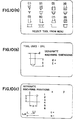
- the microprocessor MPU first executes step 40 of FIGURE 3(a), wherein one rectangular parallelepiped and one circular cylinder as the menu of the basic blank shape are simultaneously displayed by their plan views and front or elevational views on a screen 12a of the CRT display unit 12. as shown in FIGURE 8(a).
- Such display directs an operator to make by the key boad 11 a response stating that the general blank shape of the workpiece W is a rectangular parallelepiped or a circular cylinder.
- the CRT screen 12a also displays selection marks "(A)" and "(B)” respectively over the plan view of the rectangular parallelepiped and the circular cylinder, along with a message "SELECT BASIC BLANK SHAPE".
- the operator depresses an A-imprinted character key of the key board 11 when the general blank shape of the workpiece W is a rectangular parallelepiped or a B-imprinted character key of the key board 11 when it is a circular cylinder.
- the microprocessor MPU stores in a predetermined area of the random access memory RAMI data indicating that the selected basic blank shape is a rectangular parallelepiped. Then, the microprocessor MPU executes step 41 to erase the screen image shown in FIGURE 8(a) and to display the plan and elevational views of a rectangular parallelepiped respectively at upper and lower portions of a scaling zone 12b which occupies the left half of the screen 12a. A message is also displayed at the right portion of the screen 12a for requesting the operator to input data which indicate dimensions (a, b and h) of the workpiece W in the X, Y and Z-axis directions.
- Step 42 When the operator inputs the dimension data xa, b and h) in response to the message, the micropocessor MPU reads and stores these data in the random access memory RAM 2 for temporal storage. Step 42 then follows, wherein the plan and elevational views of a rectangular parallelepiped having the dimensions so input in longitudinal, transverse and height directions are displayed on the scaling zone 12b of the CRT screen 12a, as shown in FIGURE 8(c).
- the operator depresses an N-imprinted character key of the key board 11, which advances the routine of the microprocessor MPU from step 43 to step 50 of FICURE 3(b) without executing the processing for any additional blank shape.
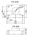
- the workpiece W has a vertical cylindrical boss as exemplified in FIGURES 12(a) and 12(b), however, the operator depresses a B-imprinted character key of the key board 11 in correspondence to a selection mark "B)" which is put on the left of the plan and elevational views of the general circular cylinder displayed on the CRT screen 12a.
- This manipulation by the operator causes the microprocessor MPU to store data indicating that the selected additional blank shape is a circular cylinder and then, to execute step 45, whereby an image shown in FIGURE 8(d) is displayed on the CRT screen 12a.
- the image includes illustrations in which lengths in X and Y-axis directions between the a:;is of the cylindrical boss and a reference point of the basic blank shape and the diameter and the height of the cylindrical boss are respectively represented by x, y, d and h.
- the image further includes a message directing that the operator designate these dimentions (x, y, d and h).
- the reference point thereof in an X-Y plane uses the left-lower conner of the basic blank shape as viewd in the plan view, and that in the case of the basic blank shape being a circular cylinder, the reference point thereof in the X-Y plane uses the axis of the circular cylinder.
- the operator In response to the message, the operator successively inputs the designated dimensions (x, y, d and h) by a set of numeric keys of of the key board 11.
- the routine is returned from step 45 to step 42, in which the microprocessor MPU generates a blank shape incorporating the cylindrical boss as an additional blank shape into the rectangular parallelepiped as a basic blank shape, based upon the input data indicative of the dimensions and position of the cylindrical boss and displays plan and elevational views of the generated blank shape at the scaling zone 12b.
- step 50 of FIGURE 3(b) the microprocessor MPU displays general shapes of the machine tool work table 25 and the basic blank shape as input at the scaling zone 12b of the CRT screen 12a, as shown in FIGURE 9. Simultaneously displyed at this time are symbols >: and y respectively indicating distances in the X and Y-axis directions between the machine origin in the X-Y plane and the reference point of the workpiece W and another Symbol Z indicating the distance between the upper surface of the work table 25 and the lower surface of the workpiece W. A message is further displayed to request that the operator designate dimensions respctively corresponding to symbols x, y and z.
- the operator inputs dimension data respectively corresponding to the symbols x, y and z by manipulating the key board 11.
- the microprocessor MPU then executes setp 51 to store these data in the random access memory RAM1 before advancing its processing to step 60 of FIGURE 3(c).
- the microprocessor MPU displays on the CRT screen 12a a menu of tools used in the machine tool 20. This display can be done by displaying on the CRT screen 12a general images of a centering tool, a drilling tool, a tapping tool, a boring tool and the like, as shown in FIGURE 10(a), so as to question the operator which tool is to be used for machinings.
- Step 61 is next executed, wherein the microprocessor MPU dislays on the CRT screen 12a the general image of a drilling hole along with a message directing the operator to input data indicative of the diameter (d) and depth (1) of the drilling hole, as shown in FIGURE 10(b).
- the microprocessor MPU When the diameter (d) and the depth (1) of the drilling hole are input in response to the message, the microprocessor MPU then displays on the CRT screen 12a a general image illustrating the relative positons (x , y) in the X and Y-axis directions between the center of the drilling hole and the reference point of the workpiece W. Another general image is simultaneously displayed to illustrate an air-cut feed amount (a) and a retraction feed amount (c) from the upper surface of the workpiece W.
- the CRT screen image at this time also includes a message directing the operator to input these necessary data (x, y, a and c).
- Step 63 is next executed, wherein the microprocessor MPU displays at the scaling zone 12b of the CRT screen 12a the figures of holes respectively superposed on portions of the figure of the workpiece blank shape which are designated by the input hole position data, as shown in FIGURE 10(d).
- a message is simultaneously displayed to question the operator as to whether a further machining is required on the workpiece W.
- the operator at this stage depresses the 2-imprinted key to instruct the microprocessor MPU that no additional machining is required.
- the microprocessor MPU completes the processings for definition of machinings and advances its routine from step 65 to step 70 of FIGURE 3(d).
- step 70 a tool which is suitable to the kind of a machining and the shape to be made by the machining is selected from a plurality of tools which are registered in a tool data file, not shown, stored in the random access memory RAMI, and a tool number of the selected tool is identified by reference to the tool data file.
- step 70 the routine of the microprocessor MPU is moved from step 70 to step 71, wherein the microprocessor MPU prepares NC data blocks for instructing that a tool to be used in a first machining step be indexed to a tool exchange position and then be attached to the tool spindle 26.
- the NC data blocks prepared in this step can be seen at, for example, block numbers "N001" and "N002" of an NC program shown in FIGURE 13.
- step 72 it is checked in step 72 what the kind of the machining is, and in step 73, an NC program, that is a number of NC data blocks are prepared in the order which depends upon the kind of the machining.
- the kind of the machining is a drilling operation, and the NC program is prepared to prescribe that the axis of the tool is successively positioned at the machining positions P1-P4 and that the tool is moved downwardly and then, upwardly along the Z-axis at each of the machining positions P1-P4.
- program portions each for a drilling cycle are successively prepared with respect to the four machining positions Pl-P4.
- Each of the program portion prescribes that after the tool is positioned right over the machining position concerned through rapid feed movement in the X-Y plane, the tool be downwardly moved to an air-cut feed starting position at a rapid feed rate.
- the program portion further prescribes that the tool then be downwardly moved to a position which is determined by the position of an upper surface of the workpiece W and the input data indicative of the drilling depth ( 1 ), at a predetermined cutting feed rate, and that subsequently, the tool be upwardly moved by the retraction feed amount (c) beyond the upper surface of the workpiece W.
- the NC program including such program portions is prepared block by block, and a plurality of NC data blcks so prepared are successively stored in an NC data area of the random access memory RAM1.
- the routine of the microprocessor MPU is moved from step 73 to 75, wherein it is ascertained whether an additional machining has been instructed or not. Since in this particular instance, the definition of machinings has been made only with respect to the drilling operations at the four machining positions P1-P4, it is determined that no additional machining has been instructed. Consequently, the microprocessor MPU discontinues the processings for NC program preparation by advancing its routine from step 75 to step 80 of FIGURE 3(e).
- step 80 Processings in step 80 and other steps successive thereto are executed for ascertaining, by simulating the prepared NC program, whether a tool which would be presently in the tool spindle 26 or the spindle head 24 would come into engagement with a workpiece W at a rapid feed rate in any positioning feed movement if the tool or the spindle head 24 were actually moved in accordance with the prepared NC program.
- step 80 is executed, wherein an interference space which depends upon the previously defined blank shape is determined as a workpiece barrier.
- step 81 and other steps successive thereto are executed to perform the interference checking.
- the processings for interference checking involve calculating a path along which the tool would be moved in accordance with a plurality of feed command data included in the prepared NC program, and when each of the feed command data under processing includes a rapid feed command, also involve checking whether the tool would come into engagement with the workpiece W or not, each time the tool would be moved a prededetermined distance.
- an interference i.e., engagement of the tool with the workpiece W at the rapid feed rate
- the routine of the microprocessor MPU is returned from step 90 to step 60 of FIGURE 3(c), in which the previously defined machinings are revised.
- FIGURE 4 shows specific processings that the microprocessor MPU executes in step 80 for generating the workpiece barrier.
- the workpiece barrier may be determined taking the bore into consideration. However, the determination of the workpiece barrier will be described hereinafter without taking any bore into consideration for the sake of brevity.
- step 100 data indicating the first input blank shape or the basic blank shape is read out in step 100, and a boundary of an interference space for the basic blank shape in a vertical direction is obtained by calculation in step 101.
- the interference space boundary in the vertical direction is set to be higher by a clearnce (S) than the upper surface of the workpiece W.
- the clearance (S) is the sum of the air-cut feed amount (a) already input in the definition of machinings and a predetermined distance ( ⁇ ).
- a Z-axis coordinate value (Zn) of the interference space boundary is calculated based upon a height dimension of the basic blank shape, a vertical space between the work table 25 and the basic blank shape (workpiece W) mounted thereon, the air-cut feed amount (a) and a Z-axis coordinate value of the upper surfance of the work table 25.
- Step 102 is then reached, wherein it is ascertained whether the basic blank shape is a circular cylinder or a rectangular parallelepiped.
- step 103 is followed, wherein absolute coordinate values (Xw, Yw) of the center of the circular cylinder in the X-Y plane are calculated based upon the workpiece mounting position data and other data.
- a workpiece barrier radius (Rw) is further calculated by adding the aforementioned clearance (S) to a radius of the circular cylinder.
- Step 105 is executed after step 102 in the case where the basic blank shape is a rectangular parallelepiped, like in this particular embodiment.
- absolute coordinate values (Xwl, Ywl), (Xwl, Yw2), (Xw2, Ywl) and (Xw2, Yw2) of the points which are respectively outwardly offset by the clearance (S) from four corners of the upper surface of the rectangular parallelepiped in the X and Y-axis directions are calculated based upon the workpiece mounting position data and the blank shape dimension data.
- the center of the work table 25 constitutes an origin of the machine tool coordiante system in the X-Y plane, and thus, distances in the X and Y-axis directions between the left-lower corner WRP as viewed in FIGURE 15(b) and the center of the work table 25 are input as the workpiece mounting position data.
- the coordinate value (Xwl) is calculated by subtracting the clearance (S) from the position data (x) already input as a part of the workpiece mounting position data, and the coordianate value (Yw1) is ealeulated by adding the clearance (S) to the position data (y) also already input as another part of the workpiece mounting position data.
- the value (Xw2) is calculated by adding the length of the basic blank shape in the X-axis direction and the double of the clearance (S) to the calculated coordinate value (Xwl), and the value (Yw2) is calculated by subtracting the length of the basic blank shape in the Y-axis direction and the double of the clearance (S) from the calculated coordinate value (Ywl).
- step 106 the microprocessor MPU ascertains in step 106 whether an additional blank shape has been input or not. If it has been input, return is made from step 106 to step 100, whereby a boudary of an interference space for the additional blank shape is obtained in the same mode of procedure as described above. Data which indicate the position of the additional blank shape relative to the reference point of the basic blank shape are utilized in setting a boundary for the additional blank shape. Since the embodiment disclosed includes a circular cylinder defined as an additional blank shape, a boundary of an interference space for the additional blank shape is also set over and around the circular cylinder portion protruding upwardly from the workpiece W, as shown in FIGURE 14.
- steps 81-91 of FIGURE 3(e) are executed to simulate the prepared NC program and to perform an interference checking in step 88 each time the tool would be moved by a predetermined distance at the rapid feed, as mentioned earlier.
- checking is made not only with the interference between the tool and the workpice, but also with the interference betweeen the spindle head 24 and the workpiece W, as specifically indicated at steps 112 and 115 in FIGURE 5.
- step 110 is first executed, wherein tool barrier data corresponding to a tool which would presently be in use in the tool spindle 26 is selected from a plurality of tool barrier data stored in the random access memorv RAM1.
- the plurality of tool barrier data are defined respectively for tools stored in the tool magazine 27 and respectively represent interference spaces of the tools.
- it is ascertained in step 111 whether or note the lower end surface SA of the tool barrier Bt for the tool would be positioned below the interference space boundary Zn in the Z-axis direction which has been set over a top end surface of the workpiece W. This ascertainment is carried out based upon the position that the spindle head 24 would occupy, data indicative of a tool length included in the selected tool barrier data and the like.
- step 112. When it is ascertained that the lower end surface SA would be below the interference space boundary Zn, an interference between the tool barrier Bt and the workpiece barrier Bw is checked in step 112. Subsequently, it is ascertained in step 113 whether the lower end surface SB of a spindle head barrier Bh would be positioned below the interference space boundary Zn or not. The position that the spindle head 24 would occupy and data indicative of the spindle head barrier Bh which defines an interference space for the spindle head 24 are taken into consideration for this ascertainment.
- step 115 is ne>:t executed to check as to an interference between the workpiece barrier Bw and the spindle head barrier Bh.
- the above-noted tool barrier Bt is defined by a length (lt) between a lower end surfance of the tool spindle 26 and a lower end of each tool T received in the tool spindle 26 and a tool barrier radius (r ) coinciding with the tool radius.
- the tool barrier radius (r ) for each tool T whose cutting portion is smaller in diameter than a grip portion thereof is chosen to coincide with the radius of the grip portion, while the tool barrier radius for each tool T whose cutting portion is larger in diameter than a grip portion thereof is chosen to conincide with the radius of the cutting portion.
- the spindle head barrier Bh is defined by an X-Y plane including the lower end surface of the tool spindle 26 and four vertical planes encompassing the spindle head 24.
- the tool barrier Bt has a circular cross-section taken along the X-Y plane although the spindle head barrier Bh has a rectangular cross-section taken along the X-Y plane. This gives a slight difference in way of processing between interference checkings respectively executed in steps 112 and 115. However, these interference checkings are substantially the same, and for the sake of brevity, only the interference checking which using the tool barrier Bt. is executed in step 112 will be described in detail hereafter.
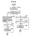
- FIGURE 6 shows specific processings for the interference checking using the tool barrier Bt.
- Step 120 is first executed to find out which sapce region in the X-axis direction the lower end surface SA of the tool barrier Bt is located at. That is, it is ascertained in this particular embodiment whether the position of the lower end surface SA in the Z-axis direction would be in the barrier defined for the basic blank shape or in the barrier defined for the additional blank shape. Determination is then made in step 121 as to whether the blank shape having the barrier in which the lower end surface SA resides is a rectangular parallelepiped or a circular cylinder, and interference processings depending upon such determination are thereafter executed,
- an interference is expected to occur between a circle and another circle, as schematically illustrated in FIGURE 15(a).
- the occurrence of an interference is detected when a distance (Is) between the axes of the tool and the additional blank shape would becomes smaller than a value which is made by the addition of the tool barrier radius (r.) to the workpiece barrier radius (Rw).
- the blank shape is a rectangular parallelepiped, on the other hand, an interference is expected to occur between a circle and a rectangular in the X-Y plane, as schematically illustrated in FIGURE 15(b).
- Steps 126-128 are executed to ascertain whether or not, the tool barrier Bt would have entered into the workpiece barrier Bw generated in step 80, and this results in checking the occurrence of the interference.
- This interference checking uses the absolulte coordinate values (Xwl, Ywl), (Xwl, Yw2), (Xw2, Ywl) and (Xw2, Yw2) which have been calculated in the foregoing step 105 for the four corner points of a square or rectangular defining a part of the workpiece barrier Bw in the X-Y plane.
- the workpiece W exemplified herein has a shape which is made by building up a circular cylinder blank shape on a rectangular blank shape.
- the interference checking according to the processings in steps 122 and 123 is executed when the lower end surface SA of the tool barrier Bt would come down beyond the highest level of the barrier defined for the additional blank shape.
- the interference checking according to the processings in steps 126-128 is then executed when the lower end surface SA of the tool barrier Bt further would come down beyond the highest level of the barrier defined for the basic blank shape.
- the moving path of the tool concerned is displayed on the screen 12a of the CRT display unit 12, with itself being superposed on each of plan and elevational views which are simultaneously displayed to show the workpiece blank shape.
- an interference is detected in this course, the occurrence of an interference is informed to the operator. This is done as shown in FIGURE 11, by displaying at the right portion of the CRT screen 12a a message indicating the occurrence of the interference and by further displaying an interference indication mark (*) at a part of each of the displyed plan and elevational views at which part the interference occurs.
- step 90 depresses the 1-imprinted numeric kev of the kev board 11 in step 90 to instruct the microprocessor MPU that the defined machininq data be revised.
- the microprocessor MPU returns its operation to step 60 of FIGURE 3(c) to execute the machining definition routine again.
- the tool retraction amount (c) must be increased in order to avoid the interference. Accordingly, when step 62 is executed, the operator changes the previously set tool retraction amount (c) to a larger one, whereby the revision of the defined machining data is completed.
- the interference checking is executed by simulating an NC program immediately after completion of an automatic programming processing, it may be executed in parallel time relation with the execution of the numerical control operation in which the machine tool 20 is actually operated in accordance with the NC program.
- the positions of the tool and the workpiece are detected at predtermined time intervals, and the checking of an interference is executed based upon the detected positions of the tool and the workpiece.
- the operation of the machine tool 20 is discontinued when the occurrence of the interference is detected.
- the above-described particular embodiment is designed to execute the interference checking processing only when any positioning feed movement would be performed at a rapid feed rate. It is however possible to execute the interference checking also when any positioning feed movement would be performed at any slower feed rate than the rapid feed rate.
- the microprocessor MPU regards any feed movement as a positioning feed movement when such any feed movement is executed at any higher feed rate than a predetermined feed rate, and executes the interf- erece checking processing during such any feed movement.
Landscapes
- Engineering & Computer Science (AREA)
- Human Computer Interaction (AREA)
- Manufacturing & Machinery (AREA)
- Physics & Mathematics (AREA)
- General Physics & Mathematics (AREA)
- Automation & Control Theory (AREA)
- Numerical Control (AREA)
Abstract
Description
- The present invention relates to a machine tool numerical controller which is capable of checking as to the interference of a cutting tool with a workpiece the relative movement between which is controlled in accordance with a numerical control program.
- Generally, when a workpiece is machined in a numerically controlled machine tool called a "machining center". programming erros involved in a numerical control program (hereafter referred to as "NC program") may cause a cutting tool to be brought into engagement with the workpiece at a rapid feed rate, thus working damages on the workpiece and the cutting tool. To avoid this, an initial program debugging must practically be carried out upon completion of preparation of the NC program or in advance of first operating the machine tool in a continuous run mode in accordance with the prepared NC program. The program debugging is done by actually operating the machine tool in a single block mode in accordance with the NC program so as to ascertain whether or not the cutting tool is brought into engagement with the workpiece at a rapid feed rate.
- Such program debugging is however impossible to perform while the machine tool is in operation for machining another workpiece in accordance with a different NC program, and therefore, disadvantageously leads to inefficient use of the machine tool. Further, in the program debugging, a programmer or operator has to make judgement of whether or not the cutting tool will come into collision with the workpiece, before the occurrence of such collision. The machine tool during the program debugging must therefore be moved at a considerably slower feed rate than that given in the NC program, and a long period of time is spent for such program debugging. Particularly, workpieces machined by machining centers have various shapes of protrusions and cavities and are more complicated in shape than those machined by lathes or turning machines. Thus, the programming of NC programs for the workpieces machined by machining centers is liable to involve errors, and the checking of the NC programs for such errors is practically unable to be made otherwise than actually operating the machining centers in accordance with the NC programs.
- By the way, there has been used a technology for checking as to whether or not a workpiece interferes with other machine tool components such as, for example, a spindle head, a tool support and the like than a tool which is infed against the workpiece to effect machinings thereon.
- However, in the known interference checking technology, it is designed to check as to the interference between two relatively movable objects which should normally not occur, and an interference space is set to define an area which the movable objects are absolutely inhibited to enter. Accordingly, it is impossible to use the known interference checking technology in checking an interference or a rapid feed engagement between a tool and a workpiece. This is because the known interference checking technology.if were used, makes it impossible to infeed the tool against the workpiece.
- It is therefore a primary object of the present invention to provide an improved machine tool numerical controller capable of preventing a cutting tool from coming into engagement with a workpiece at any higher feed rate such as a rapid feed rate than various cutting feed rates.
- Another object of the present invention is to provide an improved machine tool numerical controller capable of executing the debugging of an NC program in a short period of time by defining an interference space which inhibits engagement of a cutting tool with a workpiece only in rapid feed positioning movement.
- Another object of the present invention is to provide an improved machine tool numerical controller wherein without actually operating a machine tool in accordance with an NC program, the debugging of the NC program is executed by ascertaining, by calculation, whether one of a tool and a tool interference space defined outwardly of the outer periphery of the tool would interfere with a workpiece interference space defined outwardly of the outer periphery of a workpiece if relative movement between the tool and the workpiece were controlled in accordance with the NC program.
- A further object of the present invention is to provide an improved machine tool numerical controller wherein a workpiece interference space which is defined outwardly of the outer periphery of a workpiece to be machined for inhibiting entry of a cutting tool thereinto in rapid feed positioning movement is automatically defined based upon data indicating the blank shape and dimension of the workpiece and data indicating a mounting position of the workpiece on a machine tool work table.
- Briefly, according to the present invention, there is provided a machine tool numerical controller comprising a data input device, a data storage device, a calculation device and an interference detection device. The data input device is provided for inputting blank shape data and mounting position data for storage in the data storage device.
- The blank shape data indicates the blank shape and dimension of a workpiece to be machined by a machine tool, and the mounting position data indicates a mounting position of the workpiece on a work table of the machine tool.
- The data storage device stores an NC program in addition to the blank shape data and the mounting position data.
- The calculation device defines by calculation a workpiece interference space outwardly of the outer periphery of the workpiece, based upon the blank shape data and the mounting position data stored in the data storage device. The interference detection device ascertains whether one of the tool and a tool interference space defined outwardly of the outer periphery of the tool enters the workpiece interference space in rapid feed positioning movement, by calculation or through actual relative movement between a tool spindle carrying the tool and the work table in accordance with the NC program.
- With this configuration, since the workpiece interference space is automatically defined, a manual data input by an operator is unnecessary for the definition of the workpiece interference space, and errors can be prevented from being involved in such a manual data input. Consequently, the debugging of the NC program can be reliably executed in a short period of time. Particularly, since not only the blank shape data but also the mounting position data is used to define the workpiece interference space, a position on the work table where the workpiece interference space is generated can be automatically shifted with a change in the mounting position of the workpiece on the work table.
- Furthermore, the occurrence of an interference between the tool and the workpiece is determined when entry of one of the tool and the tool interference space into the workpiece interference space at a rapid feed rate is ascertained actually or in calculation. Accordingly, the tool is prevented from coming into engagement with the workpiece at the rapid feed rate when the debugging of the NC program is executed by actually operating the machine tool in accordance with the NC program or when the machine tool is operated in accordance with the NC program for the machining of the workpiece. Particularly, it is practically possible to execute the debugging of the NC program with the machine tool being operated at the feed rate as designated in the NC program.
- In another aspect of the present invention, another calculation device is provided for calculating a tool path along which the tool spindle would be moved relative to the work table in accordance with the NC program. The interference detection device in this aspect detects whether or not one of the tool and the tool interference space would be engaged with the workpiece interference space in any rapid feed positioning movement if the relative movement between the tool spindle and the work table were controlled in accordance with the NC program. Since the detection by the interference detection device is done by calculation based upon the tool path and the tool and workpiece interference spaces, the debugging of the NC program can be executed- without actually operating the machine tool in accordance with the NC program.
- The foregoing and various other objects and many of the attendant advantages of the present invention will be readily appreciated as the same becomes better understood by reference to the following detailed description of a preferred embodiment when considered in connection with the accompanying drawings, wherein like reference numerals designate identical or corresponding parts throughout the several views, and in which:
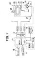
- FIGURE 1 is a general block diagram of a machine tool numerical controller according to the present invention. also showing a schematic elevational view of a machine tool controllable by the numerical controller:
- FIGURE 2 is a general flow chart of a part of system control program executed by a microprocessor shown in FIGURE 1;
- FIGURES 3(a)-3(e) are specific flow charts of a blank shape definition routine, a mounting position definition routine, a machining definition routine, an NC program preparation routine and an interference checking routine which are executed by the microprocessor respectively in steps (i), (ii), (iii), (iv) and (v) of FIGURE 2;
- FIGURE 4 is a specific flow chart of a workpiece barrier setting routine executed by the microprocessor in
step 80 of FIGURE 3(e); - FIGURE 5 is a specific flow chart of a routine executed by the microprocessor in
step 88 of FIGURE 3(e); - FIGURE 6 is a specific flow chart of a routine executed by the microprocessor in
step 112 of FIGURE 5; - FIGURE 7 is a specific flow chart of a numerical control execution routine executed by the microprocessor to numerically control the machine tool in accordance with an NC program;
- FIGURES 8(a)-8(e) are explanatory views showing images selectively generated on a screen of a CRT display device shown in FIGURE 1 when the blank shape definition routine is e>:ecuted;
- FIGURE 9 is an explanatory view showing an image generated on the CRT screen when the mounting position definition routine is executed:
- FIGURES 10(a)-10(d) are explanatory views showing images selectively generated on the CRT screen when the machining definition routine is executed;
- FIGURE 11 is an explanatory view showing an image generated on the CRT screen in
step 125 orstep 128 of FIGURE 6; - FIGURES 12(a) and 12(b) are explanatory views showing one example of the finished shape of a workpiece;
- FIGURE 13 is an explanatory view showing an NC program prepared and used for machining the workpiece shwon in FIGURES 12(a) and 12(b); FIGURE 14 is an expanatory view showing a workpiece barrier, a tool barrier and a spindle head barrier; and
- FIGURES 15(a) and 15(b) are explanatory views respectively showing a relative positional relation between the tool barrier and a workpiece barrier and another relative positional relation between the tool barrier and a different workpiece barrier.
- Referring now to FIGURE 1, there is illustrated a central processing unit 10, which constitutes a main component of a nemerical controller. The processing unit 10 is composed of a microprocessor MPU, a read-only memory ROM, a battery-supported random access memory RAM1 free from volatility, and a random access memory RAM2 for data buffer. Connected to the microprocessor MPU through interface circuits, not shown, are a
key board 11 used as data input means, aCRT display unit 12 serving as data display means, apulse generating circuit 13 for distributing command pulses to servomotor drive circuits DUX, DUY and DUZ, and asequence control circuit 15. - A
machining center 20 controllable by the numerical controller is provided with servomotors 21-23 respectively connected to the drive circuits DUY, DUX and DUZ. The relative position betweeen a work table 25 for supporting a workpiece W and aspindle head 24 rotatably carrying atool spindle 26 is altered in three directions each perpendicular to one another when the servomotors 21-23 are rotated. Themachining center 20 is also provided with atool magazine 27 for removably storing a plurality of diverse tools and anautomatic tool exchanger 28. The tool exchanger 28 exchanges a tool in thetool spindle 26 with one of the tools selectively presented by a magazine indexing device, not shown, to a tool change position in thetool magazine 27. whereby the workpiece W can be machined with the diverse tools selectively received in thetool spindle 26. - The central processing unit 10 is operated in accordance with a system control program stored in the read-only memory ROM to selectively perform an automatic programming function and a numerical control function. The processing uint 10, in the automatic programming function, prepares a numerical control program (hereafter referred to as NC program) based upon required machining information or data which is input by the
kev board 11 in a conversational mode, and in the numerical control fuction, controls themachine tool 20, i.e., the servomotors 21-23, the magazine indexing device, thetool exchanger 28, a tool spindle drive motor, not shown, and the like, in accordance with the prepared NC program. In this particular embodiment, the automatic programming function and the numerical control function are performed by the single microprocessor MPU as follows: - That is, the microprocessor MPU first executes an automatic programming routine generally shown in FIGURE 2 to prepare an NC program for use in machining a workpiece W and to store it in an NC data area of the random access memory RAM1. Thereafter, the microprocessor MPU executes a numerical control routine shown in FIGURE 7 to control the operation of the
machine tool 20 in accordance with the NC program stored in the NC data area in the memory RAM1. - The microprocessor MPU. when executing the numerical control routine, reads out the NC data constituting the NC program, from the random access memory RAMI block by block and in accordance with each read-out NC data block, enables the
pulse generating circuit 13 to distribute feed pulses to any of the servomotor drive circuits DUX, DUY and DUZ and simultaneously, enables thesequence control circuit 15 to perform an auxiliary control operation such as , for example, a magazine indexing operation, a tool exchange operation, a spindle stop or the like. Such numerical control operation of the microprocessor MPU is the same as that of a conventional computerized numerical controller known as "CNC". Accordingly, the details of the numerical control operation the micropocessor MPU performs is omitted herein, and the automatic programming function of the micropocessor MPU will be described hereafter in detail. - As shown in FIGURE 2, processings that the microprocessor MPU executes in the automatic programming function are roughly classified into five steps (i-v) of defining the shape of an unfinished workpiece, of defining the mounting position of the workpiece relative to a machine origin, of defining machinings, of preparing an NC program and of checking interferences. The microprocessor MPU, when detecting an interference in the interfernce checking step (v), returns it processing to the machining definition step (iii) and enables the operator to revise the defined machining or machinings concerned. The foregoing five steps are executed in order as described hereafter.
- This step is to define the blank shape of a workpiece to be machined on the
machine tool 20. FIGURE 3(a) shows specific processings executed in this step. - Generally, workpieces machined by a machine tool called 4 "machining center" have a number of protrusions and cavities. However, the blank shapes of such workpieces are usually a combination of a number of rectangular parallelepipeds and circular cylinders and are formed with a number of round holes and square holes. For this reason, in this particular embodiment, one rectangular parallelepiped or one circular cylinder is used to define any basic blank shape, and one rectangular parallelepiped, one circular cylinder, one round hole or one square hole is used to define any additional blank shape. Accordingly, the entire shape of anv workpiece W can be defined by a combination of one basic blank shape and one or more additional blank shapes.
- In order to define the blank shape of a workpiece, the microprocessor MPU first executes
step 40 of FIGURE 3(a), wherein one rectangular parallelepiped and one circular cylinder as the menu of the basic blank shape are simultaneously displayed by their plan views and front or elevational views on a screen 12a of theCRT display unit 12. as shown in FIGURE 8(a). Such display directs an operator to make by the key boad 11 a response stating that the general blank shape of the workpiece W is a rectangular parallelepiped or a circular cylinder. For this purpose, the CRT screen 12a also displays selection marks "(A)" and "(B)" respectively over the plan view of the rectangular parallelepiped and the circular cylinder, along with a message "SELECT BASIC BLANK SHAPE". In response to this, the operator depresses an A-imprinted character key of thekey board 11 when the general blank shape of the workpiece W is a rectangular parallelepiped or a B-imprinted character key of thekey board 11 when it is a circular cylinder. - Assuming now that the operator depresses the A-imprinted character key for selection of the rectangular parallelepiped, the microprocessor MPU stores in a predetermined area of the random access memory RAMI data indicating that the selected basic blank shape is a rectangular parallelepiped. Then, the microprocessor MPU executes step 41 to erase the screen image shown in FIGURE 8(a) and to display the plan and elevational views of a rectangular parallelepiped respectively at upper and lower portions of a scaling zone 12b which occupies the left half of the screen 12a. A message is also displayed at the right portion of the screen 12a for requesting the operator to input data which indicate dimensions (a, b and h) of the workpiece W in the X, Y and Z-axis directions.
- When the operator inputs the dimension data xa, b and h) in response to the message, the micropocessor MPU reads and stores these data in the random
access memory RAM 2 for temporal storage.Step 42 then follows, wherein the plan and elevational views of a rectangular parallelepiped having the dimensions so input in longitudinal, transverse and height directions are displayed on the scaling zone 12b of the CRT screen 12a, as shown in FIGURE 8(c). At the same time, respective plan and elevational views of four additional blank shapes including one general rectangular parallelepiped, one general circular cylinder, one general round hole and one general square hole are also displayed at the right half of theCRT screen 12, along with a message given at the right-lower portion of theCRT screen 12 to instruct that the operator select one of the four addtional blank shapes. - If the workpiece W is a simple rectangular parallelepiped having no additional blank shape, the operator depresses an N-imprinted character key of the
key board 11, which advances the routine of the microprocessor MPU fromstep 43 to step 50 of FICURE 3(b) without executing the processing for any additional blank shape. If the workpiece W has a vertical cylindrical boss as exemplified in FIGURES 12(a) and 12(b), however, the operator depresses a B-imprinted character key of thekey board 11 in correspondence to a selection mark "B)" which is put on the left of the plan and elevational views of the general circular cylinder displayed on the CRT screen 12a. This manipulation by the operator causes the microprocessor MPU to store data indicating that the selected additional blank shape is a circular cylinder and then, to executestep 45, whereby an image shown in FIGURE 8(d) is displayed on the CRT screen 12a. The image includes illustrations in which lengths in X and Y-axis directions between the a:;is of the cylindrical boss and a reference point of the basic blank shape and the diameter and the height of the cylindrical boss are respectively represented by x, y, d and h. The image further includes a message directing that the operator designate these dimentions (x, y, d and h). It is to be noted herein that in the case of the basic blank shape being a rectangular parallelepiped, the reference point thereof in an X-Y plane uses the left-lower conner of the basic blank shape as viewd in the plan view, and that in the case of the basic blank shape being a circular cylinder, the reference point thereof in the X-Y plane uses the axis of the circular cylinder. - In response to the message, the operator successively inputs the designated dimensions (x, y, d and h) by a set of numeric keys of of the
key board 11. Upon completion of this data input, the routine is returned fromstep 45 to step 42, in which the microprocessor MPU generates a blank shape incorporating the cylindrical boss as an additional blank shape into the rectangular parallelepiped as a basic blank shape, based upon the input data indicative of the dimensions and position of the cylindrical boss and displays plan and elevational views of the generated blank shape at the scaling zone 12b. - The addition of another additional blank shape can be done in succession by repeating manipulations similar to those described above. Exemplifying the workpiece shown in FIGURES 12(a) and 12(b), reference characters PI-P4 denote holes to be machined, of which no additional blank shape is thus required to be defined. Accordingly, when
step 42 is executed after the addtional blank shape of the cylindrical boss is defined, an N-imprinted key of thekey board 11 is depressed because of no further additional blank shape provided. This causes the microprocessor MPU to advance its processing fromstep 43 to step 50 of FIGURE 3(b) with the result of completing the foregoing processings for definition of a blank shape. - Definition of Workpiece Mounting Position When
step 50 of FIGURE 3(b)is reached, the microprocessor MPU displays general shapes of the machine tool work table 25 and the basic blank shape as input at the scaling zone 12b of the CRT screen 12a, as shown in FIGURE 9. Simultaneously displyed at this time are symbols >: and y respectively indicating distances in the X and Y-axis directions between the machine origin in the X-Y plane and the reference point of the workpiece W and another Symbol Z indicating the distance between the upper surface of the work table 25 and the lower surface of the workpiece W. A message is further displayed to request that the operator designate dimensions respctively corresponding to symbols x, y and z. - In response to the message, the operator inputs dimension data respectively corresponding to the symbols x, y and z by manipulating the
key board 11. The microprocessor MPU then executessetp 51 to store these data in the random access memory RAM1 before advancing its processing to step 60 of FIGURE 3(c). - Completing the processings for definitions of the blank shape and mounting positon of the workpiece W in the above-described manner, the microprocessor MPU displays on the CRT screen 12a a menu of tools used in the
machine tool 20. This display can be done by displaying on the CRT screen 12a general images of a centering tool, a drilling tool, a tapping tool, a boring tool and the like, as shown in FIGURE 10(a), so as to question the operator which tool is to be used for machinings. - Assuming now that in the machining of the workpiece W shown in FIGURES 12(a) and 12(b), through holes each having the same diameter as one another are to be made respectively at four conner portions P1-P4 of the workpiece W, the operator inputs a numeral "2" by depressing the 2-imprinted numeric key corresponding to data "(2)" over the drilling tool on the CRT screen 12a. The microprocessor MPU thus recognizes that the kind of a machining to be performed is a drilling operation.
Step 61 is next executed, wherein the microprocessor MPU dislays on the CRT screen 12a the general image of a drilling hole along with a message directing the operator to input data indicative of the diameter (d) and depth (1) of the drilling hole, as shown in FIGURE 10(b). - When the diameter (d) and the depth (1) of the drilling hole are input in response to the message, the microprocessor MPU then displays on the CRT screen 12a a general image illustrating the relative positons (x , y) in the X and Y-axis directions between the center of the drilling hole and the reference point of the workpiece W. Another general image is simultaneously displayed to illustrate an air-cut feed amount (a) and a retraction feed amount (c) from the upper surface of the workpiece W. The CRT screen image at this time also includes a message directing the operator to input these necessary data (x, y, a and c).
- In response to the message, the operator successively inputs the positions of holes at the four conner portions of the workpiece W by reference to the part drawing and further inputs the retraction feed amount (c) and the air-cut feed amount (a).
Step 63 is next executed, wherein the microprocessor MPU displays at the scaling zone 12b of the CRT screen 12a the figures of holes respectively superposed on portions of the figure of the workpiece blank shape which are designated by the input hole position data, as shown in FIGURE 10(d). A message is simultaneously displayed to question the operator as to whether a further machining is required on the workpiece W. Since in this particular instance, only the four through holes Pl-P4 should be machined on the workpiece W, the operator at this stage depresses the 2-imprinted key to instruct the microprocessor MPU that no additional machining is required. In response to this, the microprocessor MPU completes the processings for definition of machinings and advances its routine fromstep 65 to step 70 of FIGURE 3(d). - When the definition of machinings is completed in the foregoing manner, the microprocessor MPU then executes
step 70 to initiate the prepartion of an NC program. First of all, instep 70, a tool which is suitable to the kind of a machining and the shape to be made by the machining is selected from a plurality of tools which are registered in a tool data file, not shown, stored in the random access memory RAMI, and a tool number of the selected tool is identified by reference to the tool data file. When the selection of the tool is completed, the routine of the microprocessor MPU is moved fromstep 70 to step 71, wherein the microprocessor MPU prepares NC data blocks for instructing that a tool to be used in a first machining step be indexed to a tool exchange position and then be attached to thetool spindle 26. The NC data blocks prepared in this step can be seen at, for example, block numbers "N001" and "N002" of an NC program shown in FIGURE 13. - Upon completion of these processings, it is checked in
step 72 what the kind of the machining is, and instep 73, an NC program, that is a number of NC data blocks are prepared in the order which depends upon the kind of the machining. In the machining example employed herein, the kind of the machining is a drilling operation, and the NC program is prepared to prescribe that the axis of the tool is successively positioned at the machining positions P1-P4 and that the tool is moved downwardly and then, upwardly along the Z-axis at each of the machining positions P1-P4. - More specifically, program portions each for a drilling cycle are successively prepared with respect to the four machining positions Pl-P4. Each of the program portion prescribes that after the tool is positioned right over the machining position concerned through rapid feed movement in the X-Y plane, the tool be downwardly moved to an air-cut feed starting position at a rapid feed rate. The program portion further prescribes that the tool then be downwardly moved to a position which is determined by the position of an upper surface of the workpiece W and the input data indicative of the drilling depth (1), at a predetermined cutting feed rate, and that subsequently, the tool be upwardly moved by the retraction feed amount (c) beyond the upper surface of the workpiece W. The NC program including such program portions is prepared block by block, and a plurality of NC data blcks so prepared are successively stored in an NC data area of the random access memory RAM1. When the entire NC program for effecting drilling operations at the four machining positions P1-P4, the routine of the microprocessor MPU is moved from
step 73 to 75, wherein it is ascertained whether an additional machining has been instructed or not. Since in this particular instance, the definition of machinings has been made only with respect to the drilling operations at the four machining positions P1-P4, it is determined that no additional machining has been instructed. Consequently, the microprocessor MPU discontinues the processings for NC program preparation by advancing its routine fromstep 75 to step 80 of FIGURE 3(e). - Processings in
step 80 and other steps successive thereto are executed for ascertaining, by simulating the prepared NC program, whether a tool which would be presently in thetool spindle 26 or thespindle head 24 would come into engagement with a workpiece W at a rapid feed rate in any positioning feed movement if the tool or thespindle head 24 were actually moved in accordance with the prepared NC program. First of all, step 80 is executed, wherein an interference space which depends upon the previously defined blank shape is determined as a workpiece barrier. - Thereafter, step 81 and other steps successive thereto are executed to perform the interference checking. The processings for interference checking involve calculating a path along which the tool would be moved in accordance with a plurality of feed command data included in the prepared NC program, and when each of the feed command data under processing includes a rapid feed command, also involve checking whether the tool would come into engagement with the workpiece W or not, each time the tool would be moved a prededetermined distance. When an interference (i.e., engagement of the tool with the workpiece W at the rapid feed rate) is detected by the simulation of the NC program and the definition of machinings has to therefore be revised, the routine of the microprocessor MPU is returned from
step 90 to step 60 of FIGURE 3(c), in which the previously defined machinings are revised. - FIGURE 4 shows specific processings that the microprocessor MPU executes in
step 80 for generating the workpiece barrier. In the case where a workpiece blank shape includes a bore, the workpiece barrier may be determined taking the bore into consideration. However, the determination of the workpiece barrier will be described hereinafter without taking any bore into consideration for the sake of brevity. - At the begining, data indicating the first input blank shape or the basic blank shape is read out in
step 100, and a boundary of an interference space for the basic blank shape in a vertical direction is obtained by calculation instep 101. As can be seen in FIGURE 14, the interference space boundary in the vertical direction is set to be higher by a clearnce (S) than the upper surface of the workpiece W. The clearance (S) is the sum of the air-cut feed amount (a) already input in the definition of machinings and a predetermined distance (α). A Z-axis coordinate value (Zn) of the interference space boundary is calculated based upon a height dimension of the basic blank shape, a vertical space between the work table 25 and the basic blank shape (workpiece W) mounted thereon, the air-cut feed amount (a) and a Z-axis coordinate value of the upper surfance of the work table 25. - Step 102 is then reached, wherein it is ascertained whether the basic blank shape is a circular cylinder or a rectangular parallelepiped. In the case of the basic blank shape being a circular cylinder,
step 103 is followed, wherein absolute coordinate values (Xw, Yw) of the center of the circular cylinder in the X-Y plane are calculated based upon the workpiece mounting position data and other data. A workpiece barrier radius (Rw) is further calculated by adding the aforementioned clearance (S) to a radius of the circular cylinder. Step 105 is executed afterstep 102 in the case where the basic blank shape is a rectangular parallelepiped, like in this particular embodiment. As shown in FIGURE 15(b), absolute coordinate values (Xwl, Ywl), (Xwl, Yw2), (Xw2, Ywl) and (Xw2, Yw2) of the points which are respectively outwardly offset by the clearance (S) from four corners of the upper surface of the rectangular parallelepiped in the X and Y-axis directions are calculated based upon the workpiece mounting position data and the blank shape dimension data. - More specifically, in this embodiment, the center of the work table 25 constitutes an origin of the machine tool coordiante system in the X-Y plane, and thus, distances in the X and Y-axis directions between the left-lower corner WRP as viewed in FIGURE 15(b) and the center of the work table 25 are input as the workpiece mounting position data. Furthermore, since positive-going directions of the X and Y-axes respectively head for the right and the lower side as viewed in FIGURE 15(b), the coordinate value (Xwl) is calculated by subtracting the clearance (S) from the position data (x) already input as a part of the workpiece mounting position data, and the coordianate value (Yw1) is ealeulated by adding the clearance (S) to the position data (y) also already input as another part of the workpiece mounting position data. Of the coordinate values (Xw2) and (Yw2) which define the four corner points together with the coordinate values (Xw1) and (Yw1), the value (Xw2) is calculated by adding the length of the basic blank shape in the X-axis direction and the double of the clearance (S) to the calculated coordinate value (Xwl), and the value (Yw2) is calculated by subtracting the length of the basic blank shape in the Y-axis direction and the double of the clearance (S) from the calculated coordinate value (Ywl).
- Upon completion of these processings, the microprocessor MPU ascertains in
step 106 whether an additional blank shape has been input or not. If it has been input, return is made fromstep 106 to step 100, whereby a boudary of an interference space for the additional blank shape is obtained in the same mode of procedure as described above. Data which indicate the position of the additional blank shape relative to the reference point of the basic blank shape are utilized in setting a boundary for the additional blank shape. Since the embodiment disclosed includes a circular cylinder defined as an additional blank shape, a boundary of an interference space for the additional blank shape is also set over and around the circular cylinder portion protruding upwardly from the workpiece W, as shown in FIGURE 14. - After the boudaries of the workpice interference space are set in this manner, processings in steps 81-91 of FIGURE 3(e) are executed to simulate the prepared NC program and to perform an interference checking in
step 88 each time the tool would be moved by a predetermined distance at the rapid feed, as mentioned earlier. In this step, checking is made not only with the interference between the tool and the workpice, but also with the interference betweeen thespindle head 24 and the workpiece W, as specifically indicated atsteps - More specifically,
step 110 is first executed, wherein tool barrier data corresponding to a tool which would presently be in use in thetool spindle 26 is selected from a plurality of tool barrier data stored in the random access memorv RAM1. The plurality of tool barrier data are defined respectively for tools stored in thetool magazine 27 and respectively represent interference spaces of the tools. Then, it is ascertained in step 111 whether or note the lower end surface SA of the tool barrier Bt for the tool would be positioned below the interference space boundary Zn in the Z-axis direction which has been set over a top end surface of the workpiece W. This ascertainment is carried out based upon the position that thespindle head 24 would occupy, data indicative of a tool length included in the selected tool barrier data and the like. When it is ascertained that the lower end surface SA would be below the interference space boundary Zn, an interference between the tool barrier Bt and the workpiece barrier Bw is checked instep 112. Subsequently, it is ascertained instep 113 whether the lower end surface SB of a spindle head barrier Bh would be positioned below the interference space boundary Zn or not. The position that thespindle head 24 would occupy and data indicative of the spindle head barrier Bh which defines an interference space for thespindle head 24 are taken into consideration for this ascertainment. When it is ascertained that the lower end surface SB of the spindle head barrier Bh would be below the workpiece interference space boundary Zn,step 115 is ne>:t executed to check as to an interference between the workpiece barrier Bw and the spindle head barrier Bh. - As can be seen in FIGURE 14, the above-noted tool barrier Bt is defined by a length (lt) between a lower end surfance of the
tool spindle 26 and a lower end of each tool T received in thetool spindle 26 and a tool barrier radius (r ) coinciding with the tool radius. The tool barrier radius (r ) for each tool T whose cutting portion is smaller in diameter than a grip portion thereof is chosen to coincide with the radius of the grip portion, while the tool barrier radius for each tool T whose cutting portion is larger in diameter than a grip portion thereof is chosen to conincide with the radius of the cutting portion. Further, as can be seen also in FIGURE 14, the spindle head barrier Bh is defined by an X-Y plane including the lower end surface of thetool spindle 26 and four vertical planes encompassing thespindle head 24. - The tool barrier Bt has a circular cross-section taken along the X-Y plane although the spindle head barrier Bh has a rectangular cross-section taken along the X-Y plane. This gives a slight difference in way of processing between interference checkings respectively executed in
steps step 112 will be described in detail hereafter. - FIGURE 6 shows specific processings for the interference checking using the tool barrier Bt. Step 120 is first executed to find out which sapce region in the X-axis direction the lower end surface SA of the tool barrier Bt is located at. That is, it is ascertained in this particular embodiment whether the position of the lower end surface SA in the Z-axis direction would be in the barrier defined for the basic blank shape or in the barrier defined for the additional blank shape. Determination is then made in
step 121 as to whether the blank shape having the barrier in which the lower end surface SA resides is a rectangular parallelepiped or a circular cylinder, and interference processings depending upon such determination are thereafter executed, - Where the blank shape is a circular cylinder, an interference is expected to occur between a circle and another circle, as schematically illustrated in FIGURE 15(a). As noted by reference to
steps step 80, and this results in checking the occurrence of the interference. This interference checking uses the absolulte coordinate values (Xwl, Ywl), (Xwl, Yw2), (Xw2, Ywl) and (Xw2, Yw2) which have been calculated in the foregoingstep 105 for the four corner points of a square or rectangular defining a part of the workpiece barrier Bw in the X-Y plane. - The workpiece W exemplified herein has a shape which is made by building up a circular cylinder blank shape on a rectangular blank shape. In the embodiment described herein, therefore, the interference checking according to the processings in
steps - As the simulation of the prepared NC program is executed in the foregoing manner for interference checking, the moving path of the tool concerned is displayed on the screen 12a of the
CRT display unit 12, with itself being superposed on each of plan and elevational views which are simultaneously displayed to show the workpiece blank shape. When an interference is detected in this course, the occurrence of an interference is informed to the operator. This is done as shown in FIGURE 11, by displaying at the right portion of the CRT screen 12a a message indicating the occurrence of the interference and by further displaying an interference indication mark (*) at a part of each of the displyed plan and elevational views at which part the interference occurs. - The operator, when so informed, depresses the 1-imprinted numeric kev of the
kev board 11 instep 90 to instruct the microprocessor MPU that the defined machininq data be revised. In response to this. the microprocessor MPU returns its operation to step 60 of FIGURE 3(c) to execute the machining definition routine again. The tool retraction amount (c) must be increased in order to avoid the interference. Accordingly, whenstep 62 is executed, the operator changes the previously set tool retraction amount (c) to a larger one, whereby the revision of the defined machining data is completed. - Although in the above-described particular embodiment, the interference checking is executed by simulating an NC program immediately after completion of an automatic programming processing, it may be executed in parallel time relation with the execution of the numerical control operation in which the
machine tool 20 is actually operated in accordance with the NC program. In this case, during the execution of the numerical control operation, the positions of the tool and the workpiece are detected at predtermined time intervals, and the checking of an interference is executed based upon the detected positions of the tool and the workpiece. The operation of themachine tool 20 is discontinued when the occurrence of the interference is detected. - Furthermore, the above-described particular embodiment is designed to execute the interference checking processing only when any positioning feed movement would be performed at a rapid feed rate. It is however possible to execute the interference checking also when any positioning feed movement would be performed at any slower feed rate than the rapid feed rate. In this case, the microprocessor MPU regards any feed movement as a positioning feed movement when such any feed movement is executed at any higher feed rate than a predetermined feed rate, and executes the interf- erece checking processing during such any feed movement.
- Obviously, numerous modifications and variations of the present invention are possible in light of the above teachings. It is therefore to be understood that within the scope of the appended claims, the invention may be practiced otherwise than as specifically described herein.
Claims (4)
Applications Claiming Priority (2)
| Application Number | Priority Date | Filing Date | Title |
|---|---|---|---|
| JP45945/82 | 1982-03-23 | ||
| JP57045945A JPS58163001A (en) | 1982-03-23 | 1982-03-23 | Numerical controller equipped with interference checking function |
Publications (3)
| Publication Number | Publication Date |
|---|---|
| EP0089561A2 true EP0089561A2 (en) | 1983-09-28 |
| EP0089561A3 EP0089561A3 (en) | 1985-11-13 |
| EP0089561B1 EP0089561B1 (en) | 1990-06-13 |
Family
ID=12733408
Family Applications (1)
| Application Number | Title | Priority Date | Filing Date |
|---|---|---|---|
| EP83102369A Expired - Lifetime EP0089561B1 (en) | 1982-03-23 | 1983-03-10 | Machine tool numerical controller with an interference checking function |
Country Status (4)
| Country | Link |
|---|---|
| US (1) | US4513366A (en) |
| EP (1) | EP0089561B1 (en) |
| JP (1) | JPS58163001A (en) |
| DE (1) | DE3381652D1 (en) |
Cited By (13)
| Publication number | Priority date | Publication date | Assignee | Title |
|---|---|---|---|---|
| EP0104409A2 (en) * | 1982-09-07 | 1984-04-04 | General Electric Company | A method of establishing safe zones in a numerically controlled machine |
| EP0144585A2 (en) * | 1983-10-26 | 1985-06-19 | Dr. Johannes Heidenhain GmbH | Method for the perspective visualisation of changeable shapes |
| EP0144426A1 (en) * | 1983-05-17 | 1985-06-19 | Fanuc Ltd. | Method of checking tool interference |
| EP0150217A1 (en) * | 1983-06-17 | 1985-08-07 | Fanuc Ltd. | Numerical control apparatus with function for checking stored stroke limit of drawing |
| EP0113682A3 (en) * | 1983-01-11 | 1986-08-27 | Mitsubishi Denki Kabushiki Kaisha | Numerical control system and method of displaying images therein |
| EP0192822A2 (en) * | 1985-02-22 | 1986-09-03 | Hitachi, Ltd. | Method of preparing numerical control data for inserting components |
| US4653108A (en) * | 1983-12-08 | 1987-03-24 | Dr. Johannes Heidenhain Gmbh | Electrical circuit for a microprocessor graphic system |
| DE3706291A1 (en) * | 1986-02-27 | 1987-09-03 | Mitsubishi Electric Corp | WORK PROGRAM TEST DEVICE |
| DE3707579A1 (en) * | 1986-03-10 | 1987-09-24 | Mitsubishi Electric Corp | NUMERIC CONTROL DEVICE |
| FR2600790A1 (en) * | 1986-06-26 | 1987-12-31 | Toshiba Machine Co Ltd | METHOD FOR GENERATING TOOL PATHS |
| EP0257099A1 (en) * | 1986-01-24 | 1988-03-02 | Fanuc Ltd. | Device for detecting various errors in set values for injection molding machine |
| WO1995008142A1 (en) * | 1993-09-13 | 1995-03-23 | Grundig Aktiengesellschaft | Process for the two-dimensional determination of a work-area contour for lathes |
| EP0697639A1 (en) * | 1994-08-15 | 1996-02-21 | Toshiba Kikai Kabushiki Kaisha | Method for checking interference, method for checking processing program, and method for checking processing propriety |
Families Citing this family (63)
| Publication number | Priority date | Publication date | Assignee | Title |
|---|---|---|---|---|
| JPS59216208A (en) * | 1983-05-23 | 1984-12-06 | Mitsubishi Electric Corp | Numerical control device |
| KR890001314B1 (en) * | 1983-05-23 | 1989-04-29 | Mitsubishi Electric Corp | Numbering control apparatus |
| DE3324951A1 (en) * | 1983-07-11 | 1985-01-24 | M.A.N.- Roland Druckmaschinen AG, 6050 Offenbach | DEVICE FOR DETERMINING AND EVALUATING COLOR MEASURING FIELDS ON A PRINT SHEET LYING ON A MEASURING TABLE WITH A DENSITOMETER |
| JPS6044293A (en) * | 1983-08-18 | 1985-03-09 | 株式会社日立製作所 | Control system of industrial robot |
| JPS60101608A (en) * | 1983-11-07 | 1985-06-05 | Mitsubishi Electric Corp | Numerical controller |
| JPS60126710A (en) * | 1983-12-14 | 1985-07-06 | Fanuc Ltd | Method for determining working process in automatic programming |
| US4636938A (en) * | 1984-08-31 | 1987-01-13 | Cincinnati Milacron Inc. | Method and apparatus for producing numerical control programs |
| US4618924A (en) * | 1984-09-28 | 1986-10-21 | General Electric Company | Automatic machining using constructive solid geometry with Boolean combinations of primitives including tool offsets to form a machining pattern |
| US4799408A (en) * | 1985-02-21 | 1989-01-24 | General Electric Company | Automatic cutting bit recovery |
| JPH0611458B2 (en) * | 1985-06-27 | 1994-02-16 | ファナック株式会社 | Tool shape display device |
| JPS6222107A (en) * | 1985-07-22 | 1987-01-30 | Fanuc Ltd | Nc data preparing method |
| JPS6257852A (en) * | 1985-09-04 | 1987-03-13 | Toyoda Mach Works Ltd | Automatic programming device |
| US4727473A (en) * | 1986-01-02 | 1988-02-23 | Fischer & Porter Company | Self-learning mechanism for a set of nested computer graphics |
| JPS62199338A (en) * | 1986-02-27 | 1987-09-03 | Fanuc Ltd | Automatic prevention device for tool collision |
| US4758961A (en) * | 1986-07-10 | 1988-07-19 | Yamazaki Machinery Works, Ltd. | Tool move control method and apparatus for preventing tool interference with an object. |
| US4953075A (en) * | 1986-12-16 | 1990-08-28 | Spectra Physics, Inc. | Control system for a sample preparation system |
| US4833617A (en) * | 1987-08-14 | 1989-05-23 | General Electric Company | Solid modeling based adaptive feedrate control for NC machining |
| JPS6462706A (en) * | 1987-09-03 | 1989-03-09 | Fanuc Ltd | Nc program output system |
| US4979121A (en) * | 1987-09-25 | 1990-12-18 | Yamazaki Mazak Corporation | Control method and apparatus for controlling machining operations in a machine tool having a plurality of coordinate systems |
| JPH01159705A (en) * | 1987-12-17 | 1989-06-22 | Fanuc Ltd | Parts shape inputting method |
| US4935865A (en) * | 1988-06-02 | 1990-06-19 | The United States Of America As Represented By The Secretary Of The Air Force | Computer controlled electropolishing system |
| JPH02122304A (en) * | 1988-10-31 | 1990-05-10 | Fanuc Ltd | Executing method for part program |
| JPH0688191B2 (en) * | 1988-11-15 | 1994-11-09 | オ−クマ株式会社 | A method for determining a machining part in a numerical control information creation device |
| IL89484A (en) * | 1989-03-03 | 1992-08-18 | Nct Ltd Numerical Control Tech | System for automatic finishing of machined parts |
| DE4027987A1 (en) * | 1989-09-04 | 1991-03-21 | Brother Ind Ltd | NUMERICALLY CONTROLLED MACHINE TOOL WITH AUTOMATIC TOOL CHANGING DEVICE AND AN INDEX DEVICE |
| US5144740A (en) * | 1989-09-04 | 1992-09-08 | Brother Kogyo Kabushiki Kaisha | Numerically controlled machine tool with automatic tool exchange device and indexing device |
| US5122966A (en) * | 1989-09-18 | 1992-06-16 | Northern Research & Engineering | Computer generated tool path interference check method |
| US5121319A (en) * | 1989-10-23 | 1992-06-09 | International Business Machines Corporation | Method and apparatus for selective suspension and resumption of computer based manufacturing processes |
| US5043906A (en) * | 1989-11-24 | 1991-08-27 | Ford Motor Company | Absolute gouge avoidance for computer-aided control of cutter paths |
| US5293106A (en) * | 1989-12-11 | 1994-03-08 | Murata Kikai Kabushiki Kaisha | Program reviewing device in numerical control processing apparatus |
| JP3019398B2 (en) * | 1990-01-21 | 2000-03-13 | ソニー株式会社 | Free-form surface machining data creation method |
| KR950001058B1 (en) * | 1990-04-23 | 1995-02-08 | 마쯔시다덴기산교 가부시기가이샤 | Apparatus for supporting the development of sequence software to be used in automatic equipment and method thereof |
| US5097602A (en) * | 1990-07-09 | 1992-03-24 | Westinghouse Electric Corp. | Apparatus and method for automated inspection of a surface contour on a workpiece |
| WO1992004665A1 (en) * | 1990-09-04 | 1992-03-19 | Fellows Corporation | Control graphics system for gear shaping machines |
| JPH04122543A (en) * | 1990-09-10 | 1992-04-23 | Mitsubishi Electric Corp | Numerical control device and tool replacing position changing method |
| JP2757590B2 (en) * | 1991-07-04 | 1998-05-25 | 三菱電機株式会社 | Numerical control unit |
| EP0539179B1 (en) * | 1991-10-24 | 1999-06-16 | Canon Kabushiki Kaisha | Kinematic-simulation apparatus and kinematic-simulation method |
| JP2974183B2 (en) * | 1991-11-07 | 1999-11-08 | オークマ株式会社 | Interference check device for numerically controlled machine tools |
| US5970769A (en) * | 1992-03-19 | 1999-10-26 | Laser Products, Inc. | Apparatus for bending sheet stock |
| JPH06114679A (en) * | 1992-10-06 | 1994-04-26 | Fanuc Ltd | Processing program checking method of numerical control device |
| US5526272A (en) * | 1993-01-18 | 1996-06-11 | Canon Kabushiki Kaisha | Data preparation device and method for preparing data for machining work |
| JPH09325804A (en) * | 1996-06-06 | 1997-12-16 | Toshiba Mach Co Ltd | Automatic nc program generation device for roll machining |
| US6128546A (en) * | 1996-09-30 | 2000-10-03 | Cincinnati Incorporated | Method and apparatus for a cutting system for avoiding pre-cut features |
| US6311100B1 (en) * | 1998-09-14 | 2001-10-30 | Mass. Institute Of Technology | Tool path generator for computer aided manufacturing |
| DE19846426A1 (en) * | 1998-10-08 | 2000-04-13 | Open Mind Software Technologie | Multi axis machining center with independent control of the axes of the cutting tool |
| SG96615A1 (en) * | 2000-05-01 | 2003-06-16 | Gen Electric | Method for machining a workpiece |
| DE10039970B4 (en) * | 2000-08-16 | 2007-06-21 | Homag Maschinenbau Ag | Machining center and method for processing multiple workpieces |
| US6665580B1 (en) * | 2000-09-18 | 2003-12-16 | Thermwood Corporation | Automatic cutting tool management system for a computer numeric controlled machining system |
| JP2006004275A (en) * | 2004-06-18 | 2006-01-05 | Fanuc Ltd | Numerical control device |
| JP4362095B2 (en) * | 2004-08-20 | 2009-11-11 | オークマ株式会社 | Numerical controller |
| US7318767B2 (en) * | 2004-10-05 | 2008-01-15 | Ruger, Barthelt & Abel | Device and method for machine control |
| JP4221016B2 (en) * | 2006-07-25 | 2009-02-12 | ファナック株式会社 | Numerical control device for interference check |
| US7909690B2 (en) * | 2006-08-08 | 2011-03-22 | Igt | Gaming device and method providing calculated reel symbol evaluation |
| US8577655B2 (en) * | 2008-06-26 | 2013-11-05 | Siemens Product Lifecycle Management Software Inc. | System and method for constructing virtual NC controllers for machine tool simulation |
| JP5142880B2 (en) * | 2008-08-06 | 2013-02-13 | 株式会社豊田中央研究所 | Machining parameter optimization device, machining parameter optimization method and program |
| CN102439525B (en) * | 2009-05-20 | 2014-03-05 | 三菱电机株式会社 | Method and device for machining simulation |
| TWI402130B (en) * | 2011-01-12 | 2013-07-21 | Ind Tech Res Inst | Interference preventing method and device |
| JP6102185B2 (en) | 2012-10-31 | 2017-03-29 | 株式会社ジェイテクト | Machine tool operation restriction device |
| JP6290835B2 (en) * | 2015-08-27 | 2018-03-07 | ファナック株式会社 | Numerical control device and machine learning device |
| US10384347B2 (en) | 2016-03-25 | 2019-08-20 | Seiko Epson Corporation | Robot control device, robot, and simulation device |
| JP6743453B2 (en) * | 2016-03-30 | 2020-08-19 | セイコーエプソン株式会社 | Robot controller, robot and simulation device |
| JP6747916B2 (en) * | 2016-08-31 | 2020-08-26 | ファナック株式会社 | Numerical control device with tool retract function to avoid interference |
| JP7303405B1 (en) * | 2022-10-31 | 2023-07-04 | ヤマザキマザック株式会社 | MACHINING SIMULATION DEVICE, MACHINE TOOL, MACHINE TOOL SYSTEM, MACHINING SIMULATION METHOD AND PROGRAM |
Citations (3)
| Publication number | Priority date | Publication date | Assignee | Title |
|---|---|---|---|---|
| US4131836A (en) * | 1976-09-10 | 1978-12-26 | Okuma Machinery Works Ltd. | Interference prevention system for machine tool movable members |
| GB2008287A (en) * | 1977-11-21 | 1979-05-31 | Fmc Corp | Apparatus for sensing the position of an articulated arm |
| DE3118065A1 (en) * | 1981-05-07 | 1982-11-25 | Stute, Gottfried, Prof. Dr.-Ing., 7000 Stuttgart | Process for preventing collisions in grinding machines, and device for this purpose |
Family Cites Families (6)
| Publication number | Priority date | Publication date | Assignee | Title |
|---|---|---|---|---|
| US4150326A (en) * | 1977-09-19 | 1979-04-17 | Unimation, Inc. | Trajectory correlation and error detection method and apparatus |
| JPS54155378A (en) * | 1978-05-29 | 1979-12-07 | Toyoda Mach Works Ltd | Operating area limiter for numerical control device |
| JPS5624608A (en) * | 1979-08-07 | 1981-03-09 | Fanuc Ltd | Numerical value control system |
| JPS56164405A (en) * | 1980-05-21 | 1981-12-17 | Mitsubishi Electric Corp | Conversation type numerical control method |
| JPS5719809A (en) * | 1980-07-10 | 1982-02-02 | Fanuc Ltd | Numerical control information generating system |
| JPS57144638A (en) * | 1981-02-26 | 1982-09-07 | Koichiro Kitamura | Protective device for automatic tool changing device |
-
1982
- 1982-03-23 JP JP57045945A patent/JPS58163001A/en active Granted
-
1983
- 1983-03-10 EP EP83102369A patent/EP0089561B1/en not_active Expired - Lifetime
- 1983-03-10 DE DE8383102369T patent/DE3381652D1/en not_active Expired - Fee Related
- 1983-03-15 US US06/475,509 patent/US4513366A/en not_active Expired - Fee Related
Patent Citations (3)
| Publication number | Priority date | Publication date | Assignee | Title |
|---|---|---|---|---|
| US4131836A (en) * | 1976-09-10 | 1978-12-26 | Okuma Machinery Works Ltd. | Interference prevention system for machine tool movable members |
| GB2008287A (en) * | 1977-11-21 | 1979-05-31 | Fmc Corp | Apparatus for sensing the position of an articulated arm |
| DE3118065A1 (en) * | 1981-05-07 | 1982-11-25 | Stute, Gottfried, Prof. Dr.-Ing., 7000 Stuttgart | Process for preventing collisions in grinding machines, and device for this purpose |
Non-Patent Citations (1)
| Title |
|---|
| PROCEEDINGS OF THE FOURTEENTH ANNUAL MEETING AND TECHNICAL CONFERENCE OF THE NUMERICAL CONTROL SOCIETY, Pittsburgh, 13th-16th March 1977, pages 37-51, Numerical Control Society, Inc., Glenview, Illinois, US; R.G. DREWRY: "NC graphics for program debugging and tape verification" * |
Cited By (23)
| Publication number | Priority date | Publication date | Assignee | Title |
|---|---|---|---|---|
| EP0104409A2 (en) * | 1982-09-07 | 1984-04-04 | General Electric Company | A method of establishing safe zones in a numerically controlled machine |
| EP0104409A3 (en) * | 1982-09-07 | 1985-10-30 | General Electric Company | A method of establishing safe zones in a numerically controlled machine |
| EP0113682A3 (en) * | 1983-01-11 | 1986-08-27 | Mitsubishi Denki Kabushiki Kaisha | Numerical control system and method of displaying images therein |
| EP0144426A1 (en) * | 1983-05-17 | 1985-06-19 | Fanuc Ltd. | Method of checking tool interference |
| EP0144426A4 (en) * | 1983-05-17 | 1986-11-04 | Fanuc Ltd | Method of checking tool interference. |
| EP0150217A1 (en) * | 1983-06-17 | 1985-08-07 | Fanuc Ltd. | Numerical control apparatus with function for checking stored stroke limit of drawing |
| EP0150217A4 (en) * | 1983-06-17 | 1987-10-19 | Fanuc Ltd | Numerical control apparatus with function for checking stored stroke limit of drawing. |
| EP0144585A2 (en) * | 1983-10-26 | 1985-06-19 | Dr. Johannes Heidenhain GmbH | Method for the perspective visualisation of changeable shapes |
| EP0144585A3 (en) * | 1983-10-26 | 1987-01-28 | Dr. Johannes Heidenhain Gmbh | Method for the perspective visualisation of changeable shapes |
| US4791579A (en) * | 1983-10-26 | 1988-12-13 | Dr. Johannes Heidenhain Gmbh | Process and apparatus for graphically representing a variable structure in perspective |
| US4653108A (en) * | 1983-12-08 | 1987-03-24 | Dr. Johannes Heidenhain Gmbh | Electrical circuit for a microprocessor graphic system |
| EP0192822A2 (en) * | 1985-02-22 | 1986-09-03 | Hitachi, Ltd. | Method of preparing numerical control data for inserting components |
| EP0192822A3 (en) * | 1985-02-22 | 1989-04-26 | Hitachi, Ltd. | Method of and apparatus for preparing numerical control data for inserting conponents |
| EP0257099A4 (en) * | 1986-01-24 | 1990-04-09 | Fanuc Ltd | Device for detecting various errors in set values for injection molding machine. |
| EP0257099A1 (en) * | 1986-01-24 | 1988-03-02 | Fanuc Ltd. | Device for detecting various errors in set values for injection molding machine |
| DE3706291A1 (en) * | 1986-02-27 | 1987-09-03 | Mitsubishi Electric Corp | WORK PROGRAM TEST DEVICE |
| US4788481A (en) * | 1986-03-10 | 1988-11-29 | Mitsubishi Denki Kabushiki Kaisha | Numerical control apparatus |
| DE3707579A1 (en) * | 1986-03-10 | 1987-09-24 | Mitsubishi Electric Corp | NUMERIC CONTROL DEVICE |
| FR2600790A1 (en) * | 1986-06-26 | 1987-12-31 | Toshiba Machine Co Ltd | METHOD FOR GENERATING TOOL PATHS |
| WO1995008142A1 (en) * | 1993-09-13 | 1995-03-23 | Grundig Aktiengesellschaft | Process for the two-dimensional determination of a work-area contour for lathes |
| US5654618A (en) * | 1993-09-13 | 1997-08-05 | Dr. Johannes Heidenhain Gmbh | Process for the two-dimensional determination of a work-area contour for lathes |
| EP0697639A1 (en) * | 1994-08-15 | 1996-02-21 | Toshiba Kikai Kabushiki Kaisha | Method for checking interference, method for checking processing program, and method for checking processing propriety |
| US5751584A (en) * | 1994-08-15 | 1998-05-12 | Toshiba Kikai Kabushiki Kaisha | Method for checking interference, method for checking processing program, and method for checking processing propriety |
Also Published As
| Publication number | Publication date |
|---|---|
| JPH0471202B2 (en) | 1992-11-13 |
| JPS58163001A (en) | 1983-09-27 |
| US4513366A (en) | 1985-04-23 |
| EP0089561A3 (en) | 1985-11-13 |
| DE3381652D1 (en) | 1990-07-19 |
| EP0089561B1 (en) | 1990-06-13 |
Similar Documents
| Publication | Publication Date | Title |
|---|---|---|
| US4513366A (en) | Menu programmed machine tool numerical controller with an interference checking function | |
| US4530046A (en) | Method of inputting machining information to a machine tool numerical controller and apparatus therefor | |
| US4750105A (en) | Automatic programming system including machining accuracy optimization | |
| EP0129091B1 (en) | Numerical control system, graphics display unit and machine tool | |
| US4739488A (en) | Machine tool with tool selection and work sequence determination | |
| US4636938A (en) | Method and apparatus for producing numerical control programs | |
| KR860002004B1 (en) | The processing method for numerical control | |
| JPH0158018B2 (en) | ||
| WO2000012258A1 (en) | Method and apparatus for optimizing nc programs in nc machining | |
| US4972322A (en) | Method for preparing numerical control data for a machine tool | |
| JPH0375885B2 (en) | ||
| JP2005288563A (en) | Method and device for creating working program | |
| EP0529239B1 (en) | Numerical control unit with position counter control and display | |
| JPH08263116A (en) | Interference checking method for nc lathe | |
| US5029068A (en) | NC data creation method | |
| KR920006233Y1 (en) | Machine tool | |
| EP0144435B1 (en) | Numerical control apparatus with automatic tool determination function | |
| JPH03220604A (en) | Device and method for plotting tool locus in numerical controller | |
| JPH0611456B2 (en) | Calculation method of machining route | |
| JP3711629B2 (en) | Counterboring method | |
| Spur et al. | Dynamic simulation system for NC-turning programs | |
| KR920008796B1 (en) | Machine tool with tool selection and work sequence determination | |
| JPS61203251A (en) | Tool interference check system | |
| JP2949730B2 (en) | Tool interference check device of numerical control processing machine | |
| JPH0248384B2 (en) | SUCHISEIGYOKOSAKUKIKAINIOKERUANAAKEKAKOJOKYOHYOJISEIGYOHOHO |
Legal Events
| Date | Code | Title | Description |
|---|---|---|---|
| PUAI | Public reference made under article 153(3) epc to a published international application that has entered the european phase |
Free format text: ORIGINAL CODE: 0009012 |
|
| 17P | Request for examination filed |
Effective date: 19830310 |
|
| AK | Designated contracting states |
Designated state(s): DE FR GB SE |
|
| PUAL | Search report despatched |
Free format text: ORIGINAL CODE: 0009013 |
|
| AK | Designated contracting states |
Designated state(s): DE FR GB SE |
|
| 17Q | First examination report despatched |
Effective date: 19870624 |
|
| GRAA | (expected) grant |
Free format text: ORIGINAL CODE: 0009210 |
|
| AK | Designated contracting states |
Kind code of ref document: B1 Designated state(s): DE FR GB SE |
|
| REF | Corresponds to: |
Ref document number: 3381652 Country of ref document: DE Date of ref document: 19900719 |
|
| ET | Fr: translation filed | ||
| PLBI | Opposition filed |
Free format text: ORIGINAL CODE: 0009260 |
|
| 26 | Opposition filed |
Opponent name: ROBERT BOSCH GMBH Effective date: 19910208 |
|
| PLBN | Opposition rejected |
Free format text: ORIGINAL CODE: 0009273 |
|
| STAA | Information on the status of an ep patent application or granted ep patent |
Free format text: STATUS: OPPOSITION REJECTED |
|
| 27O | Opposition rejected |
Effective date: 19920930 |
|
| PGFP | Annual fee paid to national office [announced via postgrant information from national office to epo] |
Ref country code: FR Payment date: 19940310 Year of fee payment: 12 Ref country code: DE Payment date: 19940310 Year of fee payment: 12 |
|
| PGFP | Annual fee paid to national office [announced via postgrant information from national office to epo] |
Ref country code: SE Payment date: 19940316 Year of fee payment: 12 |
|
| EAL | Se: european patent in force in sweden |
Ref document number: 83102369.2 |
|
| PG25 | Lapsed in a contracting state [announced via postgrant information from national office to epo] |
Ref country code: SE Effective date: 19950311 |
|
| PG25 | Lapsed in a contracting state [announced via postgrant information from national office to epo] |
Ref country code: FR Free format text: LAPSE BECAUSE OF NON-PAYMENT OF DUE FEES Effective date: 19951130 |
|
| PG25 | Lapsed in a contracting state [announced via postgrant information from national office to epo] |
Ref country code: DE Effective date: 19951201 |
|
| EUG | Se: european patent has lapsed |
Ref document number: 83102369.2 |
|
| PGFP | Annual fee paid to national office [announced via postgrant information from national office to epo] |
Ref country code: GB Payment date: 19960301 Year of fee payment: 14 |
|
| REG | Reference to a national code |
Ref country code: FR Ref legal event code: ST |
|
| PG25 | Lapsed in a contracting state [announced via postgrant information from national office to epo] |
Ref country code: GB Effective date: 19970310 |
|
| GBPC | Gb: european patent ceased through non-payment of renewal fee |
Effective date: 19970310 |