EP0089277A1 - Ladeeinrichtung für den Hauptkörper einer Trägerplattform, der wenigstens einen Lese-/Schreibumformer aufweist - Google Patents
Ladeeinrichtung für den Hauptkörper einer Trägerplattform, der wenigstens einen Lese-/Schreibumformer aufweist Download PDFInfo
- Publication number
- EP0089277A1 EP0089277A1 EP83400470A EP83400470A EP0089277A1 EP 0089277 A1 EP0089277 A1 EP 0089277A1 EP 83400470 A EP83400470 A EP 83400470A EP 83400470 A EP83400470 A EP 83400470A EP 0089277 A1 EP0089277 A1 EP 0089277A1
- Authority
- EP
- European Patent Office
- Prior art keywords
- main body
- platform
- arm
- flexible
- disc
- Prior art date
- Legal status (The legal status is an assumption and is not a legal conclusion. Google has not performed a legal analysis and makes no representation as to the accuracy of the status listed.)
- Granted
Links
- 238000013459 approach Methods 0.000 claims description 5
- 239000000725 suspension Substances 0.000 claims description 5
- 230000015654 memory Effects 0.000 description 9
- 238000005452 bending Methods 0.000 description 4
- 229910000831 Steel Inorganic materials 0.000 description 3
- 239000010959 steel Substances 0.000 description 3
- 238000006243 chemical reaction Methods 0.000 description 2
- 239000000956 alloy Substances 0.000 description 1
- 229910045601 alloy Inorganic materials 0.000 description 1
- 238000005266 casting Methods 0.000 description 1
- 230000007423 decrease Effects 0.000 description 1
- 238000006073 displacement reaction Methods 0.000 description 1
- 230000000694 effects Effects 0.000 description 1
- 239000000463 material Substances 0.000 description 1
- 239000002184 metal Substances 0.000 description 1
- 239000004033 plastic Substances 0.000 description 1
- 239000004417 polycarbonate Substances 0.000 description 1
- 229920000515 polycarbonate Polymers 0.000 description 1
- 230000001052 transient effect Effects 0.000 description 1
Images


Classifications
-
- G—PHYSICS
- G11—INFORMATION STORAGE
- G11B—INFORMATION STORAGE BASED ON RELATIVE MOVEMENT BETWEEN RECORD CARRIER AND TRANSDUCER
- G11B5/00—Recording by magnetisation or demagnetisation of a record carrier; Reproducing by magnetic means; Record carriers therefor
- G11B5/48—Disposition or mounting of heads or head supports relative to record carriers ; arrangements of heads, e.g. for scanning the record carrier to increase the relative speed
- G11B5/54—Disposition or mounting of heads or head supports relative to record carriers ; arrangements of heads, e.g. for scanning the record carrier to increase the relative speed with provision for moving the head into or out of its operative position or across tracks
-
- G—PHYSICS
- G11—INFORMATION STORAGE
- G11B—INFORMATION STORAGE BASED ON RELATIVE MOVEMENT BETWEEN RECORD CARRIER AND TRANSDUCER
- G11B21/00—Head arrangements not specific to the method of recording or reproducing
- G11B21/02—Driving or moving of heads
- G11B21/12—Raising and lowering; Back-spacing or forward-spacing along track; Returning to starting position otherwise than during transducing operation
Definitions
- the present invention relates to a device for loading main bodies of a platform comprising at least one read / write transducer for an information medium.
- the invention relates to the technical field of magnetic disk memories.
- Memories of this type are well known in the field of data processing. They usually include one or more magnetically coated disks which are mounted on a control unit to record data on their surface, and then to read and update this data as appropriate. When the memory comprises several disks, they are superimposed and have the same axis of rotation.
- the information is written on concentric tracks by read / write transducers which move on their surface.
- transducers are arranged on a platform which is moved radially above the surface of the disc by means of a linear or rotary actuator so that the transducers can access any information contained therein.
- the platform itself consists of two essential parts, namely on the one hand, a part called “main body” of the platform which includes the transducers and on the other hand, a suspension device of which one end is secured to the main body and the other end secured to a rigid removable arm.
- the transducers have electrical input and / or output wires connected to the electronic write and / or read circuits of the disk memory to which they belong.
- the main body of a pla te-forme has the shape of a relatively flat rectangular parallelepiped, the underside of which comprises the transducers for capturing and / or recording information.
- the large upper face contains the ends of the electrical input and / or output wires to transducers and the means making it possible to connect these wires to the electronic circuits for reading and / or writing from the disk memory.
- the underside of the main body has one or more grooves, the depth of which can reach up to a few tenths of a millimeter. This results in the existence on this face of several projecting parts which are called “skates” and which generally have the shape of skis.
- the rotation of the discs causes the existence between the underside of the main body of the platform and the face of the disc associated with the latter of a compressed air cushion which prevents the main body from touching the disc and consequently to deteriorate it. It is then said that the main body, and by extension the platform, flies above the face of the disc associated with it at a distance of a few tenths of a micron. This distance between the face of the main body looking at the disc and the disc itself is called the flight height.
- the air cushion exerts pressure on the face of the skids normally thereon and directed from the lower face to the upper face of the main body of the platform.
- the dynamic balance of platform in flight is obtained by opposing the force created by the pressure of the air cushion on the surface of the skids a force called "loading force" directed in opposite direction, applied to the upper face of the main body and module equal to that of the pressing force.
- the loading force is generally provided by a pre-stressed spring secured to the rigid arm of the actuator which carries the platform. This loading force is relatively low, of the order of 10 to 20 grams.
- flight phase is meant the transient stage during which the main body moves from its rest position until it is in stable flight, a few tenths of a micron in height above the disc surface.
- the flight phase is delicate mainly due to the turbulence of the air in the vicinity of the surface of the disc, particularly when the memory comprises several discs.
- the area delimited by two circles concentric with the disc passing one by the rest position of the main body of the platform and the other by the point on the surface of the disc where this main body is in stable flight is called the area d approach, or flight zone. It is in this area that the main body lowers towards the plane of the disc until it reaches its flight height.
- the problem to be resolved then consists in bending the flexible blade which carries the head while the actuator moves, radially or angularly as the case may be, to the reading zone of the disc and to gradually release this bending until the loading force exerted by the flexible spring blade is balanced by the compressed air cushion which forms dynamically under the pads of the read head.
- the flexible spring leaf comprises two symmetrical ramps. These ramps cooperate with fixed supports mounted on the frame which act as a cam profile with respect to the symmetrical ramps, so as to raise or lower the flexible blade when the removable arm is moved relative to the disc. This performs the loading or unloading of the read / write head.
- the present invention relates precisely to a device for loading the main body of pla te-form comprising at least one reading transducer /. writing of an information medium which can be miniaturized more easily than the known prior devices.
- This device comprises at least one rigid removable arm, a flexible spring leaf fixed to the rigid arm at one of its ends and supporting at its other end, a platform, this platform being superposed on a main body and suspension, the flexible blade producing a load force of the main body on the support.
- 11 is characterized in that it comprises means for deforming at least one wire allowing the latter to exert on the first end of the blade a force parallel to the surface of the support causing the other end to bend so that the latter moves substantially perpendicular to the information carrier.
- This loading device is applicable to both a rotary actuator and a linear actuator.
- a rotary actuator it finds a preferential application to a rotary actuator. Indeed, with a rotary actuator, it is necessary to provide for the displacement of the removable arm and we don't have the space necessary to install the fixed supports mounted on the frame. We could of course use a single ramp, but the lightness and elasticity of the flexible blade make this solution impossible, because the torque torsion thus exerted on the flexible blade would cause it to twist.
- FIG. 1 shows a perspective view of a device for loading the magnetic heads of the prior art. It consists of a support 8 secured to a rigid arm 9 (see Figures 2a and 2b). The rigid arm is itself moved in translation by means of a linear actuator driven by an electric motor. A flexible blade 10 is fixed to the support 8. The flexible blade 10 has two symmetrical ramps 5. At its end, it carries a platform 12.
- the platform 12 consists of a main body 12a and a suspension 12b.
- the main body 12a contains at least one read / write transducer making it possible to read or write data on the magnetic disc 14.
- the device also includes two fixed supports 7 mounted on the frame. These supports cooperate with the ramps 5.
- FIG. 2a illustrates the operation of this device.
- the head 12 is in flight.
- the blade 10 exerts a bearing force of the head 12 on the disc 14. There is no contact between the blade 10 and the two supports 7.
- FIG. 2B illustrates the raising of the read head.
- the rigid support arm is moved in translation in the direction of the arrow 11 and therefore the support 8 which carries the flexible blade 10.
- the two symmetrical ramps 5 forming a cam profile then mount on the fixed supports 7, which lifts the platform 12 in the direction of the arrow f above the plane of the disc 14.
- the read head is flown in the opposite direction, advancing the linear carriage towards the disc.
- the two symmetrical ramps 5 then descend on the supports 7.
- the platform 12 approaches the face of the disc 14, the lift of the platform gradually increases.
- the loading force given by the flexible blade 10 is fully balanced by the lift of the platform or read head. At this time, there is no longer contact between the flexible blade and the two supports 7.
- the rotary actuator shown in Figure 3 has been designated by the general reference 2. It consists of an arm 4 and a drive motor M (see Figure 4). The arm 4 pivots around a vertical axis 6.
- a rotary arm such as arm 4 makes it possible to reduce the inertia of the actuator by a factor of 10 compared to that of a linear actuator.
- the arm has a perforated box structure of thin alloy casting. This gives a very light and very rigid structure.
- At the end of the arm 4 is fixed at least one support 8 which carries two blades 10, mounted on either side, of which only one, the upper blade, is visible in the figure.
- At the end of the flexible blade 10 finds a head similar to that of FIGS. 1 and 2, the main body 12a of which comprises at least one transducer for reading / writing the information contained on the magnetic disc 14.
- Each face 15 of a disc is associated with a transducer.
- the expression "face of the disc” will imply the association of the latter with a transducer.
- the main body is mounted on a gimbal formed by a central ball. It positions itself relative to the air cushion that exists between it and the disc.
- the disk 14 is removable, as shown diagrammatically by the arrow 16.
- the external contour of the disk 14 during its introduction or removal has been shown diagrammatically by the line 14a, in dashed lines.
- the disc 14 is made integral with a drive device around the vertical axis 18 in the direction of the arrow 20.
- the constant speed of rotation of the disc is for example 3600 revolutions per minute.
- the flight zone in which the main body starts from its rest position and then lowers towards the plane of the disc until it reaches its flight height, has been designated by the reference 22.
- the main body 12 includes pads (not shown) under which engages the air set in motion by the rotation of the disc, which keeps the main body at a determined height above the plane of the disc. This height is called the flight height. In the case of the embodiment shown, it is 0.3 microns.
- the arm 10 is a flexible metal blade which acts as a spring. It exerts a determined bearing force of the main body on the disc. This bearing force, which varies depending on the application, can vary from 10 to 30 g.
- the actuator is mounted in a counter-inertia stirrup composed of an upper plate 24 and a thick lower steel plate 26.
- This stirrup is provided with permanent magnets 28 and polar masses 30 of the motor M.
- the two pole masses 30 determine its air gap.
- the coils 34 of the motor M are flooded by inclusion of polycarbonate under vacuum. They move in the air gap.
- the bearing which constitutes the pivot axis 6 of the loading device consists of two deep groove bearings 32 charged with a prestress in order to cancel all untimely games.
- the arm 4 comprises several main bodies, the transducers of which make it possible to write down information or to read it on several tracks.
- Platforms and the flexible arms 10 are introduced between the discs during the pivoting of the rotary arm 14. This rotary arm has been shown in reading position in FIG. 3 and. shown schematically in phantom in spread position in 4 '.
- the flexible blades 10 When the arm is in the retracted position 4 ′, the flexible blades 10 are at rest. When they are introduced between the discs, they exert a predetermined bearing force on the main body 12 on the plane of the disc. To allow the introduction of the main bodies between the discs, it is therefore necessary to bring them together so that they can penetrate between the discs without hitting them.
- the known devices in particular those which include a linear actuator, are equipped with two symmetrical ramps arranged at opposite ends of the flexible arms. These ramps apply the main body against the surface of the disc.
- the invention provides a device for loading main bodies of platforms of a different type which can be used with a rotary arm such as arm 4 (or a linear arm).
- the invention uses means of deformation of at least one wire (40) exerting on the first end of at least one blade (10) a force parallel to the surface of the support causing the bending of the other end so as to that it moves substantially perpendicular to the information carrier.
- the flexible blades being arranged in pairs, as can be seen in FIG. 4, one acts simultaneously on the ends of two flexible blades so as to bring them closer to one another. In this way the reactions perpendicular to the plane of the slide are balanced and the need to have a fixed support such as support 7 of the prior art.
- the means for acting simultaneously on the ends of two flexible blades are constituted in accordance with the invention, by two cam profiles inclined which act on a flange of each flexible blade and by means for moving these cam profiles relative to the flanges of the flexible blades.
- the cam profile exerts an action on the flexible blade which can be broken down into a component directed along the flexible blade and a component perpendicular to the flexible blade.
- the first component is balanced by the reaction of the support 8.
- the second component produces the desired effect of bringing the two flexible blades together.
- the profiles of the inclined cams are constituted by a thin steel wire 40 which forms a loop.
- the wire 40 is arranged in the axis of the flexible blade.
- the end 40a of the loop is passed through two buttonholes 43 formed in the axis of the flexible blades 10.
- the end 40a acts as a cam by pressing on the edges 44 of the buttonhole 43.
- any other means playing the same role such as a belt or hooks.
- the two blades 10 When a pull is exerted on the ends 40b of the steel wire 40, the two blades 10 are bent, which brings the main bodies 12 and 12 'closer to each other. In this way, they can be introduced into the space which separates the two discs 14 and 14 'with which they are associated.
- This space is called the inter-disk space e. In the example described, it is 5 mm.
- the main bodies 12 and 12 ′ can be introduced into the inter-disc space e without hitting the periphery of the disc at the time of their introduction.
- the traction is gradually released on the ends 40b if although they gradually approach the faces of the disc 15 and 15 'with which they are associated.
- the loading device also applies to the upper face 15a of the disc placed above the stack and to the lower face of the disc 15b placed below the stack.
- These two faces 15a and 15b constitute a special case because the main body 12 which is associated with them is not part of a pair like the main bodies 12 and 12 '.
- the flexible blades 10a and 10b which carry these transducers are not part of a couple. This is why two flexible blades 10'a and 10'b are provided, associated respectively with the blades 10a and 10b. These blades are shorter because they do not carry a main body.
- the loading device which has just been described can be miniaturized much more easily than a device of the prior art comprising two symmetrical ramps.
- a device of the prior art comprising two symmetrical ramps.
- the loading device of the invention comprises means for acting on the ends of the blades which are arranged in the axis of each blade 10 which requires much less space than the ramps of the prior art.
- these means consist of a thread passed in a loop through two buttonholes in the axis of each blade, the dimensions of the blades can be reduced considerably without particular difficulty. This allows the dimensions of the loading device and therefore the inter-disk space to be reduced, and as a result of the size of the memory itself.
- the invention also relates to means for exerting traction on the ends 40b of the loops 40.
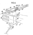
- These means consist of a jumper 47 visible in perspective on the 4.
- the jumper 47 is mounted at the end of the arm 40. It pivots around a vertical axis 44.
- the jumper 47 comprises a plurality of horizontal levers 46 fixed perpendicular to its vertical branch 48 (see FIG. 3). There are as many levers 46 as there are loops 40. In the example shown in FIGS. 3 to 5, there are therefore five levers 46.
- the ends 40b of each loop 40 are fixed to the lever 46 located at their level.
- the jumper 47 also includes a lever 50 whose end cooperates with a cam profile secured to the actuator support. This lever 50 pivots the jumper 47 during the passage of the rotary arm 4 in the flight zone 22 so as to exert traction on the ends 40b of the loops 40.
- the jumper 47 is of a very light design, made of material / plastic.
- the lever 50 carries at its end a stud 52.
- the cam profile then consists of a groove 54, the shape of which can be appreciated in FIG. 1.
- the stud 52 moves in this groove.
- the shape of the groove 54 gives control over the speed of approach of the main bodies 12 to the face of the disc by means of the movement of the jumper 47 and the speed of opening of the loops 40.
- the main bodies are unloaded in reverse order.
- the recoil of the arm 4 engages the stud 52 in the groove 54.
- the pivoting movement which results therefrom exerts traction on the loops 40 which flatten out, and consequently raise the main bodies above the surface of the disc.
- a rotational movement in the opposite direction of the jumper occurs. This movement relaxes the traction on the wires.
- the flexible blades 10 and 10 'return to their rest position.
Landscapes
- Moving Of Heads (AREA)
- Supporting Of Heads In Record-Carrier Devices (AREA)
Applications Claiming Priority (2)
| Application Number | Priority Date | Filing Date | Title |
|---|---|---|---|
| FR8204349 | 1982-03-15 | ||
| FR8204349A FR2523346B1 (fr) | 1982-03-15 | 1982-03-15 | Dispositif de chargement de corps principal de plate-forme comportant au moins un transducteur de lecture/ecriture d'un support d'informations |
Publications (2)
| Publication Number | Publication Date |
|---|---|
| EP0089277A1 true EP0089277A1 (de) | 1983-09-21 |
| EP0089277B1 EP0089277B1 (de) | 1987-02-04 |
Family
ID=9272013
Family Applications (1)
| Application Number | Title | Priority Date | Filing Date |
|---|---|---|---|
| EP83400470A Expired EP0089277B1 (de) | 1982-03-15 | 1983-03-07 | Ladeeinrichtung für den Hauptkörper einer Trägerplattform, der wenigstens einen Lese-/Schreibumformer aufweist |
Country Status (5)
| Country | Link |
|---|---|
| US (1) | US4571648A (de) |
| EP (1) | EP0089277B1 (de) |
| JP (1) | JPS58159274A (de) |
| DE (1) | DE3369763D1 (de) |
| FR (1) | FR2523346B1 (de) |
Cited By (5)
| Publication number | Priority date | Publication date | Assignee | Title |
|---|---|---|---|---|
| EP0127058A2 (de) * | 1983-05-21 | 1984-12-05 | BASF Aktiengesellschaft | Vorrichtung zum Positionieren von Gegenständen, insbesondere von Magnetköpfen |
| FR2597251A1 (fr) * | 1986-04-15 | 1987-10-16 | Mitsubishi Electric Corp | Appareil a disque magnetique |
| EP0658882A1 (de) * | 1993-12-16 | 1995-06-21 | Sony Corporation | Plattengerät |
| US5625514A (en) * | 1993-12-14 | 1997-04-29 | Sony Corporation | Disk Device |
| US8063239B2 (en) | 2006-05-09 | 2011-11-22 | Basf Se | Process for preparing aminoalkylnitriles and diamines from such nitriles |
Families Citing this family (14)
| Publication number | Priority date | Publication date | Assignee | Title |
|---|---|---|---|---|
| KR920006641B1 (ko) * | 1984-04-20 | 1992-08-10 | 가부시기가이샤 히다찌세이사꾸쇼 | 자기헤드의 위치결정장치 |
| FR2573903B1 (fr) * | 1984-11-29 | 1987-01-02 | Bull Sa | Procede pour deplacer un systeme mobile mu par un moteur electrique suivant une trajectoire donnee et dispositif de mise en oeuvre de ce procede |
| FR2573904B1 (fr) * | 1984-11-29 | 1987-01-02 | Bull Sa | Procede pour deplacer un systeme mobile mu par un moteur electrique suivant une trajectoire donnee |
| JPS63106974A (ja) * | 1986-10-16 | 1988-05-12 | インタ−ナショナル・ビジネス・マシ−ンズ・コ−ポレ−ション | デイスク記憶装置 |
| FR2609201B1 (fr) * | 1986-12-30 | 1989-10-27 | Bull Sa | Tete d'ecriture magnetique et de lecture optique d'un support d'informations |
| JP2539075B2 (ja) * | 1990-04-18 | 1996-10-02 | 株式会社東芝 | 磁気記録再生装置 |
| US5585980A (en) * | 1994-06-09 | 1996-12-17 | International Business Machines Corporation | Low friction device for an actuator arm of a disk drive |
| US6151190A (en) * | 1996-08-26 | 2000-11-21 | Sony Corporation | Removable disk storage apparatus and device for accessing the recording medium supported therein |
| US5826325A (en) * | 1997-07-10 | 1998-10-27 | International Business Machines Corporation | Method of merging heads |
| US5973886A (en) * | 1997-11-14 | 1999-10-26 | Castlewood Systems | Adjustable head load ramp for digital video disk drive system |
| US6208489B1 (en) * | 1998-04-16 | 2001-03-27 | Seagate Technology Llc | Head stack-level load/unload mechanism for rigid disk drives |
| JP2000163899A (ja) * | 1998-11-30 | 2000-06-16 | Fujitsu Ltd | 記録ディスク駆動装置 |
| US6826018B2 (en) * | 2001-03-06 | 2004-11-30 | Matsushita Electric Industrial Co., Ltd. | Disk drive with head supporting device |
| US11875830B2 (en) * | 2021-02-10 | 2024-01-16 | Seagate Technology Llc | Adjusting HGA z-height via HSA elevator using head/actuator feedback |
Citations (2)
| Publication number | Priority date | Publication date | Assignee | Title |
|---|---|---|---|---|
| FR2089595A5 (de) * | 1970-05-25 | 1972-01-07 | Ibm | |
| FR2284952A1 (fr) * | 1974-09-16 | 1976-04-09 | Information Storage Systems | Appareil d'entrainement en rotation de disques de memoires magnetiques |
Family Cites Families (2)
| Publication number | Priority date | Publication date | Assignee | Title |
|---|---|---|---|---|
| US3646536A (en) * | 1969-12-04 | 1972-02-29 | Sli Ind | Head-positioning apparatus |
| JPS5846783B2 (ja) * | 1976-05-27 | 1983-10-18 | 日本電信電話株式会社 | 磁気デイスク装置の浮動形ヘッド支持装置 |
-
1982
- 1982-03-15 FR FR8204349A patent/FR2523346B1/fr not_active Expired
-
1983
- 1983-02-16 JP JP58024530A patent/JPS58159274A/ja active Granted
- 1983-02-16 US US06/467,202 patent/US4571648A/en not_active Expired - Fee Related
- 1983-03-07 DE DE8383400470T patent/DE3369763D1/de not_active Expired
- 1983-03-07 EP EP83400470A patent/EP0089277B1/de not_active Expired
Patent Citations (2)
| Publication number | Priority date | Publication date | Assignee | Title |
|---|---|---|---|---|
| FR2089595A5 (de) * | 1970-05-25 | 1972-01-07 | Ibm | |
| FR2284952A1 (fr) * | 1974-09-16 | 1976-04-09 | Information Storage Systems | Appareil d'entrainement en rotation de disques de memoires magnetiques |
Non-Patent Citations (2)
| Title |
|---|
| ELEKTRONISCHE RUNDSCHAU, vol. 11, no 4, 1957, pages 109-118, Berlin DE * |
| IBM TECHNICAL DISCLOSURE BULLETIN, vol 15, no. 9, février 1973, page 2750, New York US * |
Cited By (11)
| Publication number | Priority date | Publication date | Assignee | Title |
|---|---|---|---|---|
| EP0127058A2 (de) * | 1983-05-21 | 1984-12-05 | BASF Aktiengesellschaft | Vorrichtung zum Positionieren von Gegenständen, insbesondere von Magnetköpfen |
| EP0127058A3 (en) * | 1983-05-21 | 1986-03-05 | Basf Aktiengesellschaft | Positioning device for objects, particularly magnetic heads |
| FR2597251A1 (fr) * | 1986-04-15 | 1987-10-16 | Mitsubishi Electric Corp | Appareil a disque magnetique |
| US5625514A (en) * | 1993-12-14 | 1997-04-29 | Sony Corporation | Disk Device |
| EP0658882A1 (de) * | 1993-12-16 | 1995-06-21 | Sony Corporation | Plattengerät |
| EP0959455A1 (de) * | 1993-12-16 | 1999-11-24 | Sony Corporation | Plattenlaufwerk |
| EP0959458A1 (de) * | 1993-12-16 | 1999-11-24 | Sony Corporation | Plattenlaufwerk |
| EP0959457A1 (de) * | 1993-12-16 | 1999-11-24 | Sony Corporation | Plattenlaufwerk |
| EP0959456A1 (de) * | 1993-12-16 | 1999-11-24 | Sony Corporation | Plattenlaufwerk |
| US8063239B2 (en) | 2006-05-09 | 2011-11-22 | Basf Se | Process for preparing aminoalkylnitriles and diamines from such nitriles |
| US8497399B2 (en) | 2006-05-09 | 2013-07-30 | Basf Se | Process for preparing aminoalkyl nitriles and diamines from such nitriles |
Also Published As
| Publication number | Publication date |
|---|---|
| EP0089277B1 (de) | 1987-02-04 |
| JPS6222196B2 (de) | 1987-05-16 |
| FR2523346A1 (fr) | 1983-09-16 |
| JPS58159274A (ja) | 1983-09-21 |
| DE3369763D1 (en) | 1987-03-12 |
| FR2523346B1 (fr) | 1988-06-10 |
| US4571648A (en) | 1986-02-18 |
Similar Documents
| Publication | Publication Date | Title |
|---|---|---|
| EP0089277B1 (de) | Ladeeinrichtung für den Hauptkörper einer Trägerplattform, der wenigstens einen Lese-/Schreibumformer aufweist | |
| EP0222647B1 (de) | Hebungseinrichtung für magnetische Schreib- und/oder Lesekopfgleiter in einem Plattenspeichergerät | |
| FR2488764A1 (fr) | Appareil reproducteur de supports d'enregistrement rotatifs, comportant un dispositif de serrage du support d'enregistrement | |
| FR2551578A1 (fr) | Appareil d'enregistrement et/ou de lecture de disque souple | |
| FR2482350A1 (fr) | Dispositif d'aide a la platine dans un tourne-videodisque | |
| EP0210693A1 (de) | Audio- oder Videoapparat mit zwei Zahnstangen | |
| FR2728378A1 (fr) | Dispositif de mise en rotation pour la lecture d'un disque optique | |
| EP0184500B1 (de) | Verfahren zur Verschiebung eines beweglichen Systems, das durch einen elektrischen Motor in einer gegebenen Bahn angetrieben wird und Anordnung zur Realisierung dieses Verfahrens | |
| FR2552577A1 (fr) | Appareil d'enregistrement et de reproduction magnetique a cassette de bande | |
| FR2597251A1 (fr) | Appareil a disque magnetique | |
| EP0177529B1 (de) | Wiedergabegerät für mehrseitig-vielfältige videoplatten | |
| FR2539547A1 (fr) | Appareil de reproduction pour des supports d'enregistrement tournants | |
| CH628456A5 (fr) | Appareil automatique de changement de disques. | |
| FR2525796A1 (fr) | Dispositif automatique pour tourne-disques de mise en position operative d'un disque | |
| US3972533A (en) | Signal pickup lifting/lowering apparatus | |
| FR2460024A1 (fr) | Tourne-disques pour videodisque comportant un dispositif de centrage et de blocage du disque | |
| FR2472809A1 (fr) | Mecanisme d'enregistrement electromecanique de signaux d'information dans un substrat | |
| FR2472808A1 (fr) | Mecanisme d'enregistrement electromecanique de signaux d'information dans un substrat | |
| CH332874A (fr) | Mécanisme d'entraînement du support de sons pour appareil enregistreur et reproducteur de sons | |
| CH274899A (fr) | Gramophone. | |
| FR2536569A1 (fr) | Tourne-disque | |
| WO2000072229A1 (fr) | Connecteur a atterrissage | |
| BE504296A (de) | ||
| FR2590396A1 (fr) | Appareil d'enregistrement et/ou de reproduction | |
| CH362239A (fr) | Bras de pick-up pour machine parlante |
Legal Events
| Date | Code | Title | Description |
|---|---|---|---|
| PUAI | Public reference made under article 153(3) epc to a published international application that has entered the european phase |
Free format text: ORIGINAL CODE: 0009012 |
|
| AK | Designated contracting states |
Designated state(s): DE GB IT NL SE |
|
| 17P | Request for examination filed |
Effective date: 19830907 |
|
| ITF | It: translation for a ep patent filed |
Owner name: FUMERO BREVETTI S.N.C. |
|
| GRAA | (expected) grant |
Free format text: ORIGINAL CODE: 0009210 |
|
| RAP1 | Party data changed (applicant data changed or rights of an application transferred) |
Owner name: BULL S.A. |
|
| AK | Designated contracting states |
Kind code of ref document: B1 Designated state(s): DE GB IT NL SE |
|
| REF | Corresponds to: |
Ref document number: 3369763 Country of ref document: DE Date of ref document: 19870312 |
|
| PLBE | No opposition filed within time limit |
Free format text: ORIGINAL CODE: 0009261 |
|
| STAA | Information on the status of an ep patent application or granted ep patent |
Free format text: STATUS: NO OPPOSITION FILED WITHIN TIME LIMIT |
|
| 26N | No opposition filed | ||
| PGFP | Annual fee paid to national office [announced via postgrant information from national office to epo] |
Ref country code: SE Payment date: 19890126 Year of fee payment: 7 |
|
| ITTA | It: last paid annual fee | ||
| PGFP | Annual fee paid to national office [announced via postgrant information from national office to epo] |
Ref country code: NL Payment date: 19890331 Year of fee payment: 7 Ref country code: GB Payment date: 19890331 Year of fee payment: 7 |
|
| PGFP | Annual fee paid to national office [announced via postgrant information from national office to epo] |
Ref country code: DE Payment date: 19890407 Year of fee payment: 7 |
|
| PG25 | Lapsed in a contracting state [announced via postgrant information from national office to epo] |
Ref country code: GB Effective date: 19900307 |
|
| PG25 | Lapsed in a contracting state [announced via postgrant information from national office to epo] |
Ref country code: SE Effective date: 19900308 |
|
| PG25 | Lapsed in a contracting state [announced via postgrant information from national office to epo] |
Ref country code: NL Effective date: 19901001 |
|
| GBPC | Gb: european patent ceased through non-payment of renewal fee | ||
| NLV4 | Nl: lapsed or anulled due to non-payment of the annual fee | ||
| PG25 | Lapsed in a contracting state [announced via postgrant information from national office to epo] |
Ref country code: DE Effective date: 19901201 |
|
| EUG | Se: european patent has lapsed |
Ref document number: 83400470.7 Effective date: 19910110 |