EP0089009A1 - Process for the removal of the slag from molten mixtures of slag and silicon - Google Patents
Process for the removal of the slag from molten mixtures of slag and silicon Download PDFInfo
- Publication number
- EP0089009A1 EP0089009A1 EP83102340A EP83102340A EP0089009A1 EP 0089009 A1 EP0089009 A1 EP 0089009A1 EP 83102340 A EP83102340 A EP 83102340A EP 83102340 A EP83102340 A EP 83102340A EP 0089009 A1 EP0089009 A1 EP 0089009A1
- Authority
- EP
- European Patent Office
- Prior art keywords
- slag
- silicon
- partition
- melt
- graphite
- Prior art date
- Legal status (The legal status is an assumption and is not a legal conclusion. Google has not performed a legal analysis and makes no representation as to the accuracy of the status listed.)
- Granted
Links
Images
Classifications
-
- C—CHEMISTRY; METALLURGY
- C01—INORGANIC CHEMISTRY
- C01B—NON-METALLIC ELEMENTS; COMPOUNDS THEREOF; METALLOIDS OR COMPOUNDS THEREOF NOT COVERED BY SUBCLASS C01C
- C01B33/00—Silicon; Compounds thereof
- C01B33/02—Silicon
- C01B33/037—Purification
-
- C—CHEMISTRY; METALLURGY
- C22—METALLURGY; FERROUS OR NON-FERROUS ALLOYS; TREATMENT OF ALLOYS OR NON-FERROUS METALS
- C22B—PRODUCTION AND REFINING OF METALS; PRETREATMENT OF RAW MATERIALS
- C22B9/00—General processes of refining or remelting of metals; Apparatus for electroslag or arc remelting of metals
- C22B9/02—Refining by liquating, filtering, centrifuging, distilling, or supersonic wave action including acoustic waves
-
- C—CHEMISTRY; METALLURGY
- C22—METALLURGY; FERROUS OR NON-FERROUS ALLOYS; TREATMENT OF ALLOYS OR NON-FERROUS METALS
- C22B—PRODUCTION AND REFINING OF METALS; PRETREATMENT OF RAW MATERIALS
- C22B9/00—General processes of refining or remelting of metals; Apparatus for electroslag or arc remelting of metals
- C22B9/10—General processes of refining or remelting of metals; Apparatus for electroslag or arc remelting of metals with refining or fluxing agents; Use of materials therefor, e.g. slagging or scorifying agents
- C22B9/106—General processes of refining or remelting of metals; Apparatus for electroslag or arc remelting of metals with refining or fluxing agents; Use of materials therefor, e.g. slagging or scorifying agents the refining being obtained by intimately mixing the molten metal with a molten salt or slag
-
- F—MECHANICAL ENGINEERING; LIGHTING; HEATING; WEAPONS; BLASTING
- F27—FURNACES; KILNS; OVENS; RETORTS
- F27D—DETAILS OR ACCESSORIES OF FURNACES, KILNS, OVENS, OR RETORTS, IN SO FAR AS THEY ARE OF KINDS OCCURRING IN MORE THAN ONE KIND OF FURNACE
- F27D3/00—Charging; Discharging; Manipulation of charge
- F27D3/15—Tapping equipment; Equipment for removing or retaining slag
- F27D3/1545—Equipment for removing or retaining slag
-
- Y—GENERAL TAGGING OF NEW TECHNOLOGICAL DEVELOPMENTS; GENERAL TAGGING OF CROSS-SECTIONAL TECHNOLOGIES SPANNING OVER SEVERAL SECTIONS OF THE IPC; TECHNICAL SUBJECTS COVERED BY FORMER USPC CROSS-REFERENCE ART COLLECTIONS [XRACs] AND DIGESTS
- Y02—TECHNOLOGIES OR APPLICATIONS FOR MITIGATION OR ADAPTATION AGAINST CLIMATE CHANGE
- Y02P—CLIMATE CHANGE MITIGATION TECHNOLOGIES IN THE PRODUCTION OR PROCESSING OF GOODS
- Y02P10/00—Technologies related to metal processing
- Y02P10/20—Recycling
Definitions
- the invention relates to a process for removing the slag fraction from melt mixtures of slag and silicon.
- silicon-based solar cells are currently far too expensive for a broad terrestrial application. This is mainly due to the costly production of elemental silicon by thermal decomposition of gaseous silanes on heated support bodies. Less costly elemental silicon manufacturing processes are therefore becoming increasingly popular in order to reduce costs. Such processes are, for example, the aluminothermic reduction of quartz in a slag system serving as the reaction medium or the purification of elemental silicon by slag extraction.
- Such processes are, for example, the aluminothermic reduction of quartz in a slag system serving as the reaction medium or the purification of elemental silicon by slag extraction.
- the silicon is usually mixed with the slag in the form of melting drops of different sizes. Because of the low density differences, the separation of slag and silicon, which is essential for further processing, is slow; Accordingly, the silicon can then be isolated and worked up only with a great deal of time.
- the object of the invention was therefore • to provide a process which allows the rapid removal of the slag portion from melt mixtures of silicon and slag.
- melt mixtures have a hydrostatic pressure difference compared to one of are subjected to them through one or more, partially permeable partition walls made of graphite or silicon carbide and provided with polygonal, circular to slit-shaped openings of up to 10 mm inside width.
- slags based on the silicates and fluorides of the alkaline earth metals magnesium, calcium, strontium and barium can be separated off individually or in a mixture of silicon. This also applies if the slag contains other components, such as aluminum oxide formed in the aluminothermic reduction of quartz or contaminants extracted from silicon.
- sulfidic slags in particular aluminum sulfide in melt mixtures with Si-Al mixed melts.
- the working temperature is expediently chosen, at least before and during the separation process, in such a way that freezing-out of slag components or the silicon from the melt mixture and the formation of undesirable deposits in the openings of the partition wall are prevented.
- the lower limit of the suitable temperature range is close to the melting point of silicon, that is, around 1420 ° C.
- the slag can be made to freeze out in a region below the slag melting point and above the silicon melting point in a particularly favorable manner, while the still liquid silicon phase can be easily separated off, for example by pouring or siphoning off.
- the upper limit of the working temperature is basically only determined by the temperature resistance and volatility of the slag and the material from which the melt container and the partition walls are made. For example, when using a slag made of 85% by weight calcium silicate / 15% by weight calcium fluoride in a graphite container with a graphite partition, a working temperature range from 1560 to 1600 ° C. has proven to be favorable.
- the openings in the partition walls made of graphite or silicon carbide only permit the passage of the slag, but not of the silicon, in the case of melt mixtures of silicon and slag.
- These openings can have different geometries; For example, circular, oval, elliptical, but also triangular and polygonal, but above all slit-shaped cross sections are possible. Regardless of their longitudinal extension, for example with slot-like geometry, these openings remain impermeable to silicon if their clear width does not exceed 10 mm. The range of 2 to 8 mm clear width has proven to be particularly advantageous.
- the clear width of the openings can be reduced to around 100 ⁇ m, although the phase separation then slows down considerably due to the slower passage speed of the slag.
- the wall thickness of the partition walls remains largely without influence in the usual range of 10 to 30 mm with regard to the partially permeable effect and can thus be adapted to the requirements of stability without difficulty.
- the space separated from the melt mixture by the partition wall or a plurality of partition walls and the partition walls themselves can be designed in a variety of ways, depending on the manner in which the hydrostatic pressure difference with respect to the melt mixture is generated.
- the following exemplary embodiments are therefore used only to illustrate the inventive concept and are not to be understood as a limitation.
- a space can be divided by a graphite partition provided with holes, in which there is a drainage possibility on the side or in the bottom.
- a partition drawn between two side walls, but also, for example, by a cylindrical attachment located above the outlet, or by a partition covering the outlet.
- an outflow regulator is expediently provided which, by controlling the amount of slag flowing off, prevents the slag level from dropping too rapidly and thus prevents the risk of silicon flowing away prematurely.
- Suitable for this purpose is, for example, a slide which is expediently attached to the outside of the container and which can close the drainage facility after the entire amount of slag has drained away, so that only silicon remains in the container.
- a stopper rod that is immersed in the slag and that is suitable for closing off the drainage option, but also for metering the amount of slag that flows out.
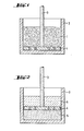
- FIG. 1 Another principle is shown in Figures 1 and 2. It consists in making the partitions movable in appropriate containers. If, as shown in FIG. 1, the melt mixture 1 is located, for example, in a container 2, on the bottom of which there is initially a partition 4, which can be moved upwards, for example by means of a graphite rod 3, and covers the base of the container, and this partition is then moved upwards, thus, as shown in FIG. 2, the slag portion 5 of the melt mixture will pass through the partition wall and remain below it, while the silicon 6 collects above it. After phase separation has been completed, the slag can be frozen out, for example by lowering the working temperature, so that only the silicon phase located above the partition remains liquid and e.g.
- an arrangement with a horizontally movable partition wall covering a side wall can also be used for phase separation.
- a partition wall rotating about the cylinder axis for example of the size of the area between the cylinder axis and the side wall, can be used in a cylindrical container, for example.
- the silicon in the melt mixture then collects in front of the rotating partition and can be poured off or siphoned off, for example, after stopping and removing the rotating partition and freezing out the slag.
- Another possibility is to use hollow displacement bodies constructed from the partition walls according to the invention immerse the melt mixture. Then the slag penetrates into the displacement bodies and can be removed with them, for example after freezing out, leaving molten silicon for further processing.
- the temperature of the crucible was then raised again to above the melting point of the remaining slag and poured out of the crucible.
- the crucible was then available for phase separation of another batch of the melt mixture. The process was carried out in a nitrogen-filled smelting plant.
Abstract
Aus Schmelzmischungen, die aus Schlacke und Silicium bestehen, läßt sich der Schlackenanteil leicht entfernen, wenn derartige Mischungen einer hydrostatischen Druckdifferenz gegenüber einem von ihnen durch eine oder mehrere, mit kreis- bis schlitzförmigen Öffnungen versehene Trennwände aus Graphit oder Siliciumcarbid abgetrennten Raum unterworfen werden. Solche Trennwände werden dann nur von der Schlacke durchdrungen, während das Silicium zurückgehalten wird.The slag portion can easily be removed from melt mixtures consisting of slag and silicon if such mixtures are subjected to a hydrostatic pressure difference compared to one of them by one or more partition walls made of graphite or silicon carbide and provided with circular to slit-shaped openings. Such partition walls are then only penetrated by the slag while the silicon is retained.
Description
Gegenstand der Erfindung ist ein Verfahren zur Entfernung des Schlackenanteils aus Schmelzmischungen von Schlacke und Silicium.The invention relates to a process for removing the slag fraction from melt mixtures of slag and silicon.
Auf dem Gebiet der photovoltaischen Stromerzeugung sind derzeit die Solarzellen auf Siliciumbasis für eine breite terrestrische Anwendung viel zu teuer. Dies liegt hauptsächlich an der kostspieligen Herstellung von.elementarem Silicium durch thermische Zersetzung gasförmiger Silane auf erhitzten Trägerkörpern. Zur Verringerung der Kosten finden daher weniger aufwendige Herstellungsverfahren von elementarem Silicium steigendes Interesse. Solche Verfahren sind beispielsweise die aluminothermische Reduktion von Quarz in einem als Reaktionsmedium dienenden Schlackensystem oder die Reinigung von elementarem Silicium durch Schlackenextraktion. Dabei liegt jedoch ein Nachteil darin, daß das Silicium gewöhnlich in Form von Schmelztropfen unterschiedlicher Größe mit der Schlacke vermischt ist. Wegen der geringen Dichteunterschiede verläuft die für die Weiterverarbeitung unerläßliche Trennung von Schlacke und Silicium nur langsam; entsprechend läßt sich das Silicium dann nur unter großem Zeitaufwand isolieren und aufarbeiten.In the field of photovoltaic power generation, silicon-based solar cells are currently far too expensive for a broad terrestrial application. This is mainly due to the costly production of elemental silicon by thermal decomposition of gaseous silanes on heated support bodies. Less costly elemental silicon manufacturing processes are therefore becoming increasingly popular in order to reduce costs. Such processes are, for example, the aluminothermic reduction of quartz in a slag system serving as the reaction medium or the purification of elemental silicon by slag extraction. However, there is a disadvantage in that the silicon is usually mixed with the slag in the form of melting drops of different sizes. Because of the low density differences, the separation of slag and silicon, which is essential for further processing, is slow; Accordingly, the silicon can then be isolated and worked up only with a great deal of time.
Aufgabe der Erfindung war•es daher, ein Verfahren anzugeben, das die rasche Entfernung des Schlackenanteils aus Schmelzmischungen von Silicium und Schlacke gestattet.The object of the invention was therefore • to provide a process which allows the rapid removal of the slag portion from melt mixtures of silicon and slag.
Gelöst wird diese Aufgabe durch ein Verfahren, welches dadurch gekennzeichnet ist, daß derartige Schmelzmischungen einer hydrostatischen Druckdifferenz gegenüber einem von ihnen durch eine oder mehrere, mit polygon-, kreis- bis schlitzförmigen Öffnungen von bis zu 10 mm lichter Weite versehene, teildurchlässige Trennwände aus Graphit oder Siliciumcarbid abgetrennten Raum unterworfen werden.This object is achieved by a method which is characterized in that such melt mixtures have a hydrostatic pressure difference compared to one of are subjected to them through one or more, partially permeable partition walls made of graphite or silicon carbide and provided with polygonal, circular to slit-shaped openings of up to 10 mm inside width.
Unerwartet wurde nämlich gefunden, daß derartige Trennwände bei Schmelzmischungen aus Silicium und Schlacke nur für die Schlacke durchlässig sind, während das Silicium zurückgehalten wird. Hingegen werden bei Abwesenheit von Schlacke die Trennwände leicht auch von Silicium benetzt und ungehindert durchdrungen.It has been found unexpectedly that such partition walls are only permeable to the slag in melt mixtures of silicon and slag, while the silicon is retained. On the other hand, in the absence of slag, the partitions are easily wetted by silicon and penetrated unhindered.
Ein solches Verhalten ist bei vielen der bei der Siliciumherstellung und -aufbereitung beispielsweise als Schutzschmelze, als Reaktionsmedium oder als Extraktionsmittel gebräuchlichen Schlackenmaterialien festzustellen. So lassen sich nach dem erfindungsgemäßen Verfahren besonders gut Schlacken auf Basis der Silikate und Fluoride der Erdalkalimetalle Magnesium, Kalzium, Strontium und Barium einzeln oder im Gemisch von Silicium abtrennen. Dies gilt auch dann, wenn die Schlacke weitere Komponenten, wie etwa bei der aluminothermischen Reduktion von Quarz entstandenes Aluminiumoxid oder aus Silicium extrahierte Verunreinigungen gelöst enthält. Das gleiche Verhalten zeigen auch sulfidische Schlacken, insbesondere Aluminiumsulfid in Schmelzmischungen mit Si-Al-Mischschmelzen.Such behavior can be observed in many of the slag materials commonly used in silicon production and processing, for example as a protective melt, as a reaction medium or as an extractant. Thus, according to the process of the invention, slags based on the silicates and fluorides of the alkaline earth metals magnesium, calcium, strontium and barium can be separated off individually or in a mixture of silicon. This also applies if the slag contains other components, such as aluminum oxide formed in the aluminothermic reduction of quartz or contaminants extracted from silicon. The same behavior is also shown by sulfidic slags, in particular aluminum sulfide in melt mixtures with Si-Al mixed melts.
Die Arbeitstemperatur wird zweckmäßig zumindest vor und während des Trennprozesses so gewählt, daß ein Ausfrieren von Schlackenkomponenten oder des Siliciums aus der Schmelzmischung und die Bildung unerwünschter Ablagerungen in den Öffnungen der Trennwand verhindert wird. Dementsprechend liegt die Untergrenze des geeigneten Temperaturbereiches in der Nähe des Schmelzpunktes von Silicium, also bei ca. 1420 °C. In der Regel wird man jedoch eine Schlacke verwenden, deren Schmelzpunkt oberhalb dem des Siliciums liegt, so daß die Arbeitstemperatur dementsprechend höher zu wählen ist. Dann kann nämlich in besonders günstiger Weise nach abgeschlossener Phasentrennung durch Absenken der'Arbeitstemperatur in einen Bereich unterhalb des Schlackenschmelzpunktes und oberhalb des Siliciumschmelzpunktes die Schlacke zum Ausfrieren gebracht werden, während sich die noch flüssige Siliciumphase beispielsweise durch Abgießen oder Abhebern leicht abtrennen läßt. Die Obergrenze der Arbeitstemperatur wird im Grunde nur durch die Temperaturbeständigkeit und Flüchtigkeit der Schlacke und des Materials bestimmt, aus dem der Schmelzenbehälter und die Trennwände gefertigt sind. Beispielsweise hat sich bei Verwendung einer Schlacke aus 85 Gew.% 'Kalziumsilikat/15 Gew.% Kalziumfluorid in einem Behältnis aus Graphit mit Graphittrennwand ein Arbeitstemperaturbereich von 1560 bis 1600 °C,als günstig erwiesen.The working temperature is expediently chosen, at least before and during the separation process, in such a way that freezing-out of slag components or the silicon from the melt mixture and the formation of undesirable deposits in the openings of the partition wall are prevented. Accordingly, the lower limit of the suitable temperature range is close to the melting point of silicon, that is, around 1420 ° C. In general, however, you will use a slag whose melting point is above that of the silicon, so that the Ar accordingly, the working temperature should be chosen higher. Then, after the phase separation has ended, the slag can be made to freeze out in a region below the slag melting point and above the silicon melting point in a particularly favorable manner, while the still liquid silicon phase can be easily separated off, for example by pouring or siphoning off. The upper limit of the working temperature is basically only determined by the temperature resistance and volatility of the slag and the material from which the melt container and the partition walls are made. For example, when using a slag made of 85% by weight calcium silicate / 15% by weight calcium fluoride in a graphite container with a graphite partition, a working temperature range from 1560 to 1600 ° C. has proven to be favorable.
Die in den Trennwänden aus Graphit oder Siliciumcarbid befindlichen Öffnungen gestatten bei Schmelzmischungen aus Silicium und Schlacke nur den Durchtritt der Schlacke, nicht aber des Siliciums. Diese Öffnungen können verschiedene Geometrie aufweisen; beispielsweise kommen kreisförmige, ovale, elliptische, aber auch drei- und mehreckige, vor allem aber auch schlitzförmige Querschnitte in Frage. Unabhängig von ihrer Längsausdehnung etwa bei schlitzartiger Geometrie bleiben diese Öffnungen für Silicium undurchlässig, wenn ihre lichte Weite 10 mm nicht übersteigt. Als besonders vorteilhaft hat sich der Bereich von 2 bis 8 mm lichter Weite erwiesen. Prinzipiell kann jedoch wegen des hohen Durchdringungsvermögens insbesondere der Erdalkalisilikat/Fluorid-Mischschlacken die lichte Weite der Öffnungen bis in den Bereich von ca. 100 um reduziert werden, obwohl sich dann wegen der geringeren Durchtrittsgeschwindigkeit der Schlacke die Phasentrennung deutlich verlangsamt. Die Wandstärke der Trennwände bleibt beispielsweise in dem gebräuchlichen Bereich von 10 bis 30 mm im Hinblick auf die teildurchlässige Wirkung weitgehend ohne Einfluß und läßt sich somit ohne Schwierigkeit den Erfordernissen der Stabilität anpassen.The openings in the partition walls made of graphite or silicon carbide only permit the passage of the slag, but not of the silicon, in the case of melt mixtures of silicon and slag. These openings can have different geometries; For example, circular, oval, elliptical, but also triangular and polygonal, but above all slit-shaped cross sections are possible. Regardless of their longitudinal extension, for example with slot-like geometry, these openings remain impermeable to silicon if their clear width does not exceed 10 mm. The range of 2 to 8 mm clear width has proven to be particularly advantageous. In principle, however, due to the high penetration capacity of the alkaline earth silicate / fluoride mixed slags in particular, the clear width of the openings can be reduced to around 100 μm, although the phase separation then slows down considerably due to the slower passage speed of the slag. The wall thickness of the partition walls, for example, remains largely without influence in the usual range of 10 to 30 mm with regard to the partially permeable effect and can thus be adapted to the requirements of stability without difficulty.
Der von der Schmelzmischung durch die Trennwand oder mehrere Trennwände abgeteilte Raum sowie die Trennwände selbst können in vielfältiger Weise gestaltet werden, je nachdem, auf welche Art die hydrostatische Druckdifferenz gegenüber der Schmelzmischung erzeugt wird. Die nachstehenden Ausführungsbeispiele dienen daher lediglich der Illustration des Erfindungsgedankens und sind nicht im Sinne einer Beschränkung zu verstehen.The space separated from the melt mixture by the partition wall or a plurality of partition walls and the partition walls themselves can be designed in a variety of ways, depending on the manner in which the hydrostatic pressure difference with respect to the melt mixture is generated. The following exemplary embodiments are therefore used only to illustrate the inventive concept and are not to be understood as a limitation.
Beispielsweise kann in einem Behältnis, etwa einem Graphittiegel, durch eine mit Löchern versehene Trennwand aus Graphit ein Raum abgeteilt sein, in dem sich seitlich oder im Boden eine Abflußmöglichkeit befindet. Dies kann z.B. durch eine zwischen zwei Seitenwände eingezogene Trennwand geschehen, aber auch etwa durch einen zylinderförmigen, über der Ausflußmöglichkeit befindlichen Aufsatz, oder durch eine die Ausflußmöglichkeit abdeckende Trennwand. Zweckmäßig wird bei derartigen Anordnungen ein Abflußregulans vorgesehen, das durch Steuerung der abfließenden Schlackenmenge ein zu rasches Absinken des Schlackenspiegels und damit die Gefahr des vorzeitigen Abfließens von Silicium verhindert. Geeignet ist für diesen Zweck beispielsweise ein - zweckmäßig an der Außenseite des Behältnisses angebrachter - Schieber, der die Abflußmöglichkeit nach Abfließen der gesamten Schlackenmenge verschließen kann, so daß in dem Behältnis nur noch Silicium zurückbleibt. Ebenso läßt sich z.B. eine in die Schlacke eintauchende Stopfenstange verwenden, die zum Verschließen der Abflußmöglichkeit, aber auch zum Dosieren der abfließenden Schlackenmenge geeignet ist.For example, in a container, such as a graphite crucible, a space can be divided by a graphite partition provided with holes, in which there is a drainage possibility on the side or in the bottom. This can e.g. done by a partition drawn between two side walls, but also, for example, by a cylindrical attachment located above the outlet, or by a partition covering the outlet. In such arrangements, an outflow regulator is expediently provided which, by controlling the amount of slag flowing off, prevents the slag level from dropping too rapidly and thus prevents the risk of silicon flowing away prematurely. Suitable for this purpose is, for example, a slide which is expediently attached to the outside of the container and which can close the drainage facility after the entire amount of slag has drained away, so that only silicon remains in the container. Likewise, e.g. Use a stopper rod that is immersed in the slag and that is suitable for closing off the drainage option, but also for metering the amount of slag that flows out.
Wird bei derartigen Anordnungen eine Schmelzmischung aus Silicium und Schlacke in den abflußlosen Teil des Behältnisses eingefüllt, so wird die Schlacke aufgrund der hydrostatischen Druckdifferenz durch die Trennwand durchtreten und durch die Abflußmöglichkeit abfließen, während das Silicium im Behältnis zurückgehalten wird. Nachdem die gesamte Schlackenmenge abgeflossen ist und das Silicium durch die Trennwand durchzutreten und abzufließen beginnt - dies ist z.B. wegen des Farbunterschiedes zwischen Silicium- und Schlackenschmelze mit bloßem Auge zu erkennen - kann beispielsweise durch Schließen des Abflusses das nahezu schlackenfreie Silicium im Behältnis zurückgehalten und weiterverarbeitet werden.If a melt mixture of silicon and slag is poured into the drainless part of the container in such arrangements, the slag will pass through the partition due to the hydrostatic pressure difference and flow away through the drainage possibility, while the silicon is retained in the container. After all of the slag has drained and the silicon through the Partition begins to pass through and flow away - this can be seen with the naked eye, for example because of the color difference between silicon and slag melt - the almost slag-free silicon can be retained in the container and further processed, for example, by closing the drain.
Ein anderes Prinzip ist in den Figuren 1 und 2 dargestellt. Es besteht darin, die Trennwände in entsprechenden Behältnissen beweglich zu gestalten. Befindet sich, wie in Figur 1 gezeigt, die Schmelzmischung 1 beispielsweise in einem Behältnis 2, auf dessen Boden zunächst eine beispielsweise mittels einer Graphitstange 3 nach oben bewegliche, die Grundfläche des Behältnisses bedeckende Trennwand 4 aufliegt, und wird diese Trennwand dann nach oben bewegt, so wird, wie in Figur 2 dargestellt, der Schlackenanteil 5 der Schmelzmischung durch die Trennwand hindurchtreten und unterhalb von ihr verbleiben, während sich darüber das Silciium 6 ansammelt. Nach abgeschlossener Phasentrennung kann beispielsweise durch Senken der Arbeitstemperatur die Schlacke ausgefroren werden, so daß nur die oberhalb der Trennwand befindliche Siliciumphase flüssig bleibt und z.B. durch Abgießen, Abschöpfen oder Abhebern abgetrennt werden kann. Nach dem selben Prinzip kann auch eine Anordnung mit einer eine Seitenwand bedeckenden, horizontal beweglichen Trennwand zur Phasentrennung eingesetzt werden. Als Grenzfall einer beweglichen Trennwand kann beispielsweise in einem zylinderförmigen Behältnis eine um die Zylinderachse rotierende Trennwand, etwa von der Größe der Fläche`zwischen Zylinderachse und Seitenwand, eingesetzt werden. Das in der Schmelzmischung befindliche Silicium sammelt sich dann vor der rotierenden Trennwand an und kann beispielsweise nach Anhalten und Entfernen der rotierenden Trennwand und Ausfrieren der Schlacke abgegossen oder abgehebert werden.Another principle is shown in Figures 1 and 2. It consists in making the partitions movable in appropriate containers. If, as shown in FIG. 1, the melt mixture 1 is located, for example, in a
Eine weitere Möglichkeit besteht darin, aus den erfindungsgemäßen Trennwänden aufgebaute, hohle Verdrängungskörper in die Schmelzmischung einzutauchen. Dann dringt die Schlacke in die Verdrängungskörper ein und kann mit ihnen, beispielsweise nach Ausfrieren, entfernt werden, wobei schmelzflüssTges Silicium zur Weiterverarbeitung zurückbleibt.Another possibility is to use hollow displacement bodies constructed from the partition walls according to the invention immerse the melt mixture. Then the slag penetrates into the displacement bodies and can be removed with them, for example after freezing out, leaving molten silicon for further processing.
Weiterhin gibt es auch die Möglichkeit, das Silicium mit Hilfe von die erfindungsgemäßen Trennwände enthaltenden Schöpfgeräten aus der Schmelzmischung abzuschöpfen. Besonders bewährt hat sich dabei die Verwendung von doppelwandigen Schöpfgeräten, beispielsweise Schöpfkellen, bei denen die Innenwand aus den erfindungsgemäßen Trennwänden besteht, während die durch einen den Abfluß der Schlacke ermöglichenden Zwischenraum davon getrennte Außenwand sowohl für die Schlacke als auch für Silicium undurchlässig ist. Beim Schöpfvorgang verbleibt dann im Innenraum der Schöpfkelle das Silicium, während der zwischen Außenwand und Trennwand befindliche Zwischenraum sich mit Schlacke füllt und so ein Ausfließen des Siliciums aus dem Innenraum verhindert. Nach Ausfrieren dieses Schlackenteils kann das schmelzflüssig gebliebene Silicium dann nahezu schlackenfrei aus dem Innenraum der Schöpfkelle abgegossen werden.Furthermore, there is also the possibility of skimming the silicon from the melt mixture with the aid of scoops containing the partition walls according to the invention. The use of double-walled ladles, for example ladles, in which the inner wall consists of the partition walls according to the invention, has proven particularly useful, while the outer wall separated by a space that allows the slag to drain away is impermeable both to the slag and to silicon. During the scooping process, the silicon then remains in the interior of the ladle, while the space between the outer wall and the partition wall fills with slag and thus prevents the silicon from flowing out of the interior. After this slag part freezes out, the molten silicon can then be poured from the interior of the ladle almost without slag.
Diese hier aufgezeigten Ausführungsformen des erfindungsgemäßen Verfahrens bieten somit, auch in anderen denkbaren Ausgestaltungen, eine einfache und rasche Möglichkeit zur Abtrennung des Schlackenanteils aus Schmelzmischungen von Schlacke und Silicium.These embodiments of the method according to the invention shown here thus offer, even in other conceivable configurations, a simple and rapid possibility of separating the slag portion from melt mixtures of slag and silicon.
In einer Figur 1 entsprechenden Anordnung, bestehend aus einem Schmelztiegel aus Feinstkorngraphit und einer dessen Boden bedeckenden, 10 mm dicken, nach oben beweglichen Trennwand aus Feinstkorngraphit, die in Form von zwei konzentrischen Kreisen 6 bzw. 8 Löcher mit 5 mm Durchmesser aufwies, wurde eine Schmelzmischung aus gleichen Teilen Silicium und Schlacke der Zusammensetzung CaO·SiO2 auf einer Temperatur von 1580 °C gehalten. Nun wurde mit einer Ge4 schwindigkeit von 10 mm/sec die an einer Graphitstange befestigte Trennwand nach oben bewegt, bis die gesamte Schlackenmenge durch sie durchgetreten und oberhalb von ihr ausschließlich Silicium vorhanden war. Nun wurde die Temperatur auf 1450 °C erniedrigt und die Schlacke ausgefroren. Das oberhalb der Trennwand befindliche, schmelzflüssige Silicium wurde durch Abgießen abgetrennt. Anschließend wurde die Temperatur des Schmelztiegels wieder bis über den Schmelzpunkt der verbliebenen Schlacke erhöht und diese aus dem Tiegel abgegossen. Der Tiegel stand anschließend für die Phasentrennung einer weiteren Charge der Schmelzmischung zur Verfügung. Das Verfahren wurde in einer stickstoffgefüllten Schmelzanlage durchgeführt.In an arrangement corresponding to FIG. 1, consisting of a crucible made of fine grain graphite and a 10 mm thick, upwardly movable partition made of fine grain graphite covering its bottom, which had 6 or 8 holes with 5 mm diameter in the form of two concentric circles Melt mixture of equal parts of silicon and slag of the composition CaO · SiO 2 on one Temperature kept at 1580 ° C. Now the partition wall attached to a graphite rod was moved upwards at a speed of 10 mm / sec until the entire amount of slag passed through it and only silicon was present above it. Now the temperature was lowered to 1450 ° C and the slag was frozen out. The molten silicon located above the partition was separated by pouring. The temperature of the crucible was then raised again to above the melting point of the remaining slag and poured out of the crucible. The crucible was then available for phase separation of another batch of the melt mixture. The process was carried out in a nitrogen-filled smelting plant.
Claims (2)
Applications Claiming Priority (2)
| Application Number | Priority Date | Filing Date | Title |
|---|---|---|---|
| DE3208877 | 1982-03-11 | ||
| DE19823208877 DE3208877A1 (en) | 1982-03-11 | 1982-03-11 | METHOD FOR REMOVING THE SLAG PART FROM MELT MIXTURES OF SLAG AND SILICON |
Publications (2)
| Publication Number | Publication Date |
|---|---|
| EP0089009A1 true EP0089009A1 (en) | 1983-09-21 |
| EP0089009B1 EP0089009B1 (en) | 1986-01-15 |
Family
ID=6157972
Family Applications (1)
| Application Number | Title | Priority Date | Filing Date |
|---|---|---|---|
| EP83102340A Expired EP0089009B1 (en) | 1982-03-11 | 1983-03-10 | Process for the removal of the slag from molten mixtures of slag and silicon |
Country Status (6)
| Country | Link |
|---|---|
| US (1) | US4515600A (en) |
| EP (1) | EP0089009B1 (en) |
| JP (1) | JPS58156519A (en) |
| CA (1) | CA1192378A (en) |
| DE (2) | DE3208877A1 (en) |
| NO (1) | NO158615C (en) |
Cited By (2)
| Publication number | Priority date | Publication date | Assignee | Title |
|---|---|---|---|---|
| CN101623695B (en) * | 2009-08-13 | 2011-05-04 | 合肥景坤新能源有限公司 | Method for cleaning graphitic silicon materials |
| WO2020221419A1 (en) * | 2019-04-29 | 2020-11-05 | Wacker Chemie Ag | Method for the removal of silicon from slag |
Families Citing this family (6)
| Publication number | Priority date | Publication date | Assignee | Title |
|---|---|---|---|---|
| US4643833A (en) * | 1984-05-04 | 1987-02-17 | Siemens Aktiengesellschaft | Method for separating solid reaction products from silicon produced in an arc furnace |
| NO316020B1 (en) * | 2001-10-10 | 2003-12-01 | Elkem Materials | Device for continuous slag treatment of silicon |
| NO318092B1 (en) * | 2002-05-22 | 2005-01-31 | Elkem Materials | Calcium-silicate-based slag, process for the preparation of calcium-silicate-based slag, and application for slag treatment of molten silicon |
| JP4966560B2 (en) * | 2005-03-07 | 2012-07-04 | 新日鉄マテリアルズ株式会社 | Manufacturing method of high purity silicon |
| CN101511731B (en) * | 2006-09-14 | 2012-02-22 | 希利贝坎库公司 | Process and apparatus for purifying low-grade silicon material |
| CN113336255B (en) * | 2021-08-05 | 2021-10-29 | 天津包钢稀土研究院有限责任公司 | Purification method of rare earth halide molten salt |
Citations (2)
| Publication number | Priority date | Publication date | Assignee | Title |
|---|---|---|---|---|
| US2355130A (en) * | 1942-12-18 | 1944-08-08 | Leland A Yerkes | Separation of molten magnesium from molten salt baths |
| US3281238A (en) * | 1963-11-13 | 1966-10-25 | Aluminum Co Of America | Treatment of molten aluminous metal |
Family Cites Families (6)
| Publication number | Priority date | Publication date | Assignee | Title |
|---|---|---|---|---|
| US2355980A (en) * | 1942-07-03 | 1944-08-15 | Iowa Mfg Company | Spare wheel carrier |
| US4113241A (en) * | 1977-09-22 | 1978-09-12 | Swiss Aluminium Ltd. | Apparatus for the filtration of molten metal in a crucible type furnace |
| US4394271A (en) * | 1981-04-23 | 1983-07-19 | Groteke Daniel E | Apparatus and method for filtration of molten metal |
| US4388286A (en) * | 1982-01-27 | 1983-06-14 | Atlantic Richfield Company | Silicon purification |
| DE3208878A1 (en) * | 1982-03-11 | 1983-09-22 | Heliotronic Forschungs- und Entwicklungsgesellschaft für Solarzellen-Grundstoffe mbH, 8263 Burghausen | SEMICONTINUOUS PROCESS FOR PRODUCING PURE SILICON |
| US4398931A (en) * | 1982-05-19 | 1983-08-16 | Minnesota Mining And Manufacturing Company | Ceramic fabric filter |
-
1982
- 1982-03-11 DE DE19823208877 patent/DE3208877A1/en not_active Withdrawn
-
1983
- 1983-01-11 JP JP58001838A patent/JPS58156519A/en active Granted
- 1983-03-01 CA CA000422637A patent/CA1192378A/en not_active Expired
- 1983-03-01 US US06/470,980 patent/US4515600A/en not_active Expired - Fee Related
- 1983-03-10 DE DE8383102340T patent/DE3361823D1/en not_active Expired
- 1983-03-10 NO NO830841A patent/NO158615C/en unknown
- 1983-03-10 EP EP83102340A patent/EP0089009B1/en not_active Expired
Patent Citations (2)
| Publication number | Priority date | Publication date | Assignee | Title |
|---|---|---|---|---|
| US2355130A (en) * | 1942-12-18 | 1944-08-08 | Leland A Yerkes | Separation of molten magnesium from molten salt baths |
| US3281238A (en) * | 1963-11-13 | 1966-10-25 | Aluminum Co Of America | Treatment of molten aluminous metal |
Cited By (2)
| Publication number | Priority date | Publication date | Assignee | Title |
|---|---|---|---|---|
| CN101623695B (en) * | 2009-08-13 | 2011-05-04 | 合肥景坤新能源有限公司 | Method for cleaning graphitic silicon materials |
| WO2020221419A1 (en) * | 2019-04-29 | 2020-11-05 | Wacker Chemie Ag | Method for the removal of silicon from slag |
Also Published As
| Publication number | Publication date |
|---|---|
| DE3361823D1 (en) | 1986-02-27 |
| NO830841L (en) | 1983-09-12 |
| JPS58156519A (en) | 1983-09-17 |
| DE3208877A1 (en) | 1983-09-22 |
| NO158615C (en) | 1988-10-12 |
| CA1192378A (en) | 1985-08-27 |
| EP0089009B1 (en) | 1986-01-15 |
| US4515600A (en) | 1985-05-07 |
| JPS6126490B2 (en) | 1986-06-20 |
| NO158615B (en) | 1988-07-04 |
Similar Documents
| Publication | Publication Date | Title |
|---|---|---|
| DE2543340C2 (en) | ||
| DE2228913B2 (en) | Method and device for rapid cooling and solidification of a melt of refractory oxide material | |
| DE2527156B2 (en) | Process for the pretreatment of molten steel in continuous casting | |
| DE1960999A1 (en) | Process for cleaning metals in the melt and suitable device for this | |
| EP0089009B1 (en) | Process for the removal of the slag from molten mixtures of slag and silicon | |
| DE4106537A1 (en) | METHOD FOR PARTLY CONTINUOUS MELTING OF CERAMIC MATERIALS IN INDUCTION MELTING OVENS WITH SINTER-CRUSTED POT, A FURNISHED OVEN AND DEVICE FOR PERIODIC MELTING | |
| EP0258818A2 (en) | Process for melting silicium powders in a crucible, and crucible used in the process | |
| DE3049053C2 (en) | Method and device for separating slag and for pouring molten steel from a container | |
| EP0390742A1 (en) | Arrangement and method for the filtration of molten metals | |
| DE1927973C3 (en) | Method and device for removing non-metallic inclusions from aluminum melts | |
| DE1917367A1 (en) | Process for the continuous casting of steel and continuous casting plant for carrying out the process | |
| DE60010646T2 (en) | METHOD AND DEVICE FOR CLEANING ALUMINUM BY DE-MIXING | |
| DE112009001864B4 (en) | Process for refining metal | |
| EP0010307B1 (en) | Process for protecting carbon bodies | |
| DE1118172B (en) | Process for treating silicon | |
| DE3334733A1 (en) | METHOD AND SYSTEM FOR THE PRODUCTION OF HIGH-PURITY ALLOYS | |
| DE1246676B (en) | Clarifier | |
| DE3030738C2 (en) | Process for the continuous casting of copper | |
| DE1758761A1 (en) | Casting process | |
| DE2329953C3 (en) | Process for increasing the casting speed and for refining the structural structure of the cast strand in the continuous casting of steel | |
| DE2127251C3 (en) | Process for the separation of phosphorus furnace slag and ferrophosphorus | |
| DE2405184A1 (en) | METHOD AND SYSTEM FOR PURIFYING METALLIC MELT THROUGH FILTER CENTRIFUGING AND COLLECTION OF FILTRATE | |
| DE2528185A1 (en) | PROCESS FOR SEPARATING THE LOW-MELTING FROM THE HIGHER-MELTING COMPONENTS OF A PARAFFIN MIXTURE AND DEVICE FOR ITS PERFORMANCE | |
| DE921594C (en) | Process for filtering molten metal | |
| DE2937163C2 (en) | Method and device for the melt-metallurgical treatment of alloys with a tendency to segregate and application of the method |
Legal Events
| Date | Code | Title | Description |
|---|---|---|---|
| PUAI | Public reference made under article 153(3) epc to a published international application that has entered the european phase |
Free format text: ORIGINAL CODE: 0009012 |
|
| 17P | Request for examination filed |
Effective date: 19830310 |
|
| AK | Designated contracting states |
Designated state(s): BE DE FR IT |
|
| ITF | It: translation for a ep patent filed |
Owner name: SOCIETA' ITALIANA BREVETTI S.P.A. |
|
| GRAA | (expected) grant |
Free format text: ORIGINAL CODE: 0009210 |
|
| AK | Designated contracting states |
Designated state(s): BE DE FR IT |
|
| REF | Corresponds to: |
Ref document number: 3361823 Country of ref document: DE Date of ref document: 19860227 |
|
| ET | Fr: translation filed | ||
| PLBE | No opposition filed within time limit |
Free format text: ORIGINAL CODE: 0009261 |
|
| STAA | Information on the status of an ep patent application or granted ep patent |
Free format text: STATUS: NO OPPOSITION FILED WITHIN TIME LIMIT |
|
| 26N | No opposition filed | ||
| PG25 | Lapsed in a contracting state [announced via postgrant information from national office to epo] |
Ref country code: BE Effective date: 19890331 |
|
| BERE | Be: lapsed |
Owner name: HELIOTRONIC FORSCHUNGS- UND ENTWICKLUNGSG- FUR SO Effective date: 19890331 |
|
| PG25 | Lapsed in a contracting state [announced via postgrant information from national office to epo] |
Ref country code: FR Free format text: LAPSE BECAUSE OF NON-PAYMENT OF DUE FEES Effective date: 19891130 |
|
| PG25 | Lapsed in a contracting state [announced via postgrant information from national office to epo] |
Ref country code: DE Effective date: 19891201 |
|
| REG | Reference to a national code |
Ref country code: FR Ref legal event code: ST |
|
| REG | Reference to a national code |
Ref country code: FR Ref legal event code: ST |