EP0088872A2 - Assemblage semi-automatique de tubes flexibles à un élément - Google Patents
Assemblage semi-automatique de tubes flexibles à un élément Download PDFInfo
- Publication number
- EP0088872A2 EP0088872A2 EP19830100876 EP83100876A EP0088872A2 EP 0088872 A2 EP0088872 A2 EP 0088872A2 EP 19830100876 EP19830100876 EP 19830100876 EP 83100876 A EP83100876 A EP 83100876A EP 0088872 A2 EP0088872 A2 EP 0088872A2
- Authority
- EP
- European Patent Office
- Prior art keywords
- cam
- jaw members
- stripper
- tubing
- commodity
- Prior art date
- Legal status (The legal status is an assumption and is not a legal conclusion. Google has not performed a legal analysis and makes no representation as to the accuracy of the status listed.)
- Withdrawn
Links
- 230000001360 synchronised effect Effects 0.000 claims description 2
- 239000002904 solvent Substances 0.000 abstract description 11
- 238000000034 method Methods 0.000 abstract description 5
- 230000000694 effects Effects 0.000 abstract description 4
- 239000000306 component Substances 0.000 abstract 7
- 238000001990 intravenous administration Methods 0.000 description 3
- 239000000463 material Substances 0.000 description 3
- 239000004033 plastic Substances 0.000 description 3
- 229920003023 plastic Polymers 0.000 description 3
- 229920000915 polyvinyl chloride Polymers 0.000 description 3
- 239000004800 polyvinyl chloride Substances 0.000 description 3
- 238000007789 sealing Methods 0.000 description 3
- 239000000853 adhesive Substances 0.000 description 2
- 230000001070 adhesive effect Effects 0.000 description 2
- 238000010276 construction Methods 0.000 description 2
- 238000003780 insertion Methods 0.000 description 2
- 230000037431 insertion Effects 0.000 description 2
- 229910000831 Steel Inorganic materials 0.000 description 1
- 239000000654 additive Substances 0.000 description 1
- 230000000996 additive effect Effects 0.000 description 1
- 230000000712 assembly Effects 0.000 description 1
- 238000000429 assembly Methods 0.000 description 1
- 238000007796 conventional method Methods 0.000 description 1
- 230000000994 depressogenic effect Effects 0.000 description 1
- 229920001971 elastomer Polymers 0.000 description 1
- 229920002457 flexible plastic Polymers 0.000 description 1
- 239000000203 mixture Substances 0.000 description 1
- 229920002635 polyurethane Polymers 0.000 description 1
- 239000004814 polyurethane Substances 0.000 description 1
- 239000013557 residual solvent Substances 0.000 description 1
- 239000010959 steel Substances 0.000 description 1
- 230000000007 visual effect Effects 0.000 description 1
Images


Classifications
-
- B—PERFORMING OPERATIONS; TRANSPORTING
- B23—MACHINE TOOLS; METAL-WORKING NOT OTHERWISE PROVIDED FOR
- B23P—METAL-WORKING NOT OTHERWISE PROVIDED FOR; COMBINED OPERATIONS; UNIVERSAL MACHINE TOOLS
- B23P19/00—Machines for simply fitting together or separating metal parts or objects, or metal and non-metal parts, whether or not involving some deformation; Tools or devices therefor so far as not provided for in other classes
- B23P19/04—Machines for simply fitting together or separating metal parts or objects, or metal and non-metal parts, whether or not involving some deformation; Tools or devices therefor so far as not provided for in other classes for assembling or disassembling parts
- B23P19/08—Machines for placing washers, circlips, or the like on bolts or other members
- B23P19/084—Machines for placing washers, circlips, or the like on bolts or other members for placing resilient or flexible rings, e.g. O-rings, circlips
Definitions
- This invention relates to an apparatus for semiautomatically assembling a length of flexible tubing onto a component part. More particularly, it relates to an apparatus for securing a length of flexible I.V. tubing to a component in an I.V. set without the use of solvents, the apparatus affording uniform stretching of the tubing by jaw members and placement of the tubing on a portion of the component parts, at a variable depth, after which the tubing is stripped from the jaw members by a simultaneous movement of a stripper cam which engages the tubing and a rod member engaging the commodity.
- One solventless method for securing a component to flexible tubing employs jaw members to expand the tubing with a portion of the component being placed in the expanded tubing. Placement of the component is through the center of the expanded jaws.
- the prior art does not provide a method of solventless bonding of flexible tubing to a component which will afford a secure fitment of the tubing to the commodity and do so in a manner which requires few materials and a minimum amount of cost.
- Those apparatus which do not employ solvents and utilize jaws to expand the tubing have created problems in effecting a nonuniform stretching of the tubing. This has caused assembly problems due to the jaws opening in a nonparallel or duck-bill type movement, thus creating a greater stretching of the tubing at the mouth of the jaws than at the inner end.
- Other advantages are an apparatus for solventless sealing of flexible tubing to an I.V. component which affords consistently good sealing between the tubing and the component, effects a sealing between a length of flexible tubing and the components such that it is adapted to a semiautomatic and efficient operation, accomplishes a securing of polyvinylchloride tubing to a rigid plastic component without the introduction of an additive component: and an apparatus for placing a length of I.V. tubing on I.V. components of various sizes and geometric configurations which does not appreciably add to the cost of the set.
- the apparatus employs a multiplicity of jaw members, each having a longitudinal portion and dimension to fit within the length of the tubing.
- a housing and head section provide pivotal movement of the jaw members.
- a stripper cam is positioned for movement with respect to the jaw members and cam means are provided between the jaw members and the stripper cam to afford movement of the jaw members from a closed position to an open position spaced therefrom while maintaining a parallel relationship with respect to the jaw members.
- Passage means are defined within the stripper cam means for movement of the commodity therethrough.
- Commodity feed means are operatively positioned with respect to the passage means for placement and movement of the commodity therethrough.
- Drive means are provided to move the stripper cam in a forward and backward motion with respect to the jaw members.
- the commodity feed means includes a push rod member for movement of the commodity through the passage means and the means to move the stripper cam is synchronized with movement of the push rod member for simultaneous forward movement for removal of the tubing from the jaws and onto the commodity.
- the stripper cam and jaw members have cam means which are designed to afford a spacing apart of the jaw members in two different open positions with one of the open positions being a full open position.
- a passageway is disposed in stripper cam.
- the use of three jaws in conjunction with the stripper cam has been found to work well with the camming means between the two elements being afforded by two roller members forming a portion of the cam follower on the jaws and two camming surfaces on the stripper cam.
- the drive means to move the stripper cam means and push rod member are provided in part by independent rotating cam surfaces and cam followers including linkage arms to afford linear motion to the stripper cam and push rod member.
- two of the assembly apparatus are housed in a single machine and the commodity feed means includes a shuttle means to place the commodity in the passage means.
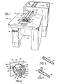
- the novel apparatus is indicated generally by the numeral 10 and includes two of the assembly units generally 12 and 13 supported on table portion 15 and extending onto a component feed cabinet 17.
- a conveyor portion 19 with visual conveyor conduits 21 and 25 extends between the head section or housing 20 and feed cabinet 17.
- Head section 20 includes a shuttle bar 22 with head assemblies 23 and 24. Included with table portion 15 are contact switches 18 and drive housing 16.
- each head section such as 23 includes three jaw members 27, 28 and 29 pivotally mounted between block members 31, 32 and 33 which are secured to head plate 35 by bolts 36.
- Each jaw member 27, 28 and 29 terminates in jaws such as 38.
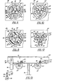
- FIGURES 5, 6, 7 and 8 illustrate the various positions and camming action of the jaw members 27, 28 and 29 as well as stripper cam 42.
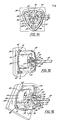
- FIGURES 9 - 16 show the various elements forming the head section 20 for each assembly unit 12 and 13 with assembly unit 12 being described in detail. It will be appreciated that each assembly unit will include one stipper cam 42 and for purposes of illustration in FIGURES 5 - 8, one jaw member 29 is illustrated.
- Stripper cam 42 will provide a camming surface generally 43 which will include two recessed camming surfaces 46 and 47 as well as linear camming surfaces 104 and 83 for engagement with rollers 50 and 51 which are rotatably mounted on jaw member 29.
- a plate portion 63 is placed adjacent camming surface 47 to provide an additional camming surface for roller 51.
- a commodity 53 in the form of a tubular body to form a reseal unit is positioned above a passage means 55 disposed centrally in the stripper cam 42.
- An oscillating and transversely movable shuttle mechanism 22 is disposed above passageway 55 in which is placed push rod 57.
- a biasing means in the form of an elastic band 60 is accommodated in slot 61 of the jaw members 27, 28 and 29 (see FIGURE 2) for biasing the roller cams such as 50 and 51 of the jaw members against the camming surfaces 43, 46 and 47 of stripper cam 42.
- slots such as 62 are provided in head plate 35 to permit lateral pivoting of the jaw members.
- Jaw member 29 is pivotally attached to head section 20 through a pivot roller 65 suitably positioned between head plate 35 and backing plate 56 by suitable means such as by a mounting shaft. The two plates 35 and 56 are secured by bolt 14. A jaw 40 extends upwardly and outwardly from jaw member 29.
- stripper cam 42 will provide three opposing camming surfaces 43, 44 and 45 for contact with rollers 51, 50, 52, 59 and 49, 58 of the respective jaw members 29, 27 and 28.
- Each of the camming surfaces 43, 44 and 45 will include two indented or depressed surface portions such as 46 and 47 as well as adjacent linear camming surfaces 83 and 104 for contact with the respective rollers.
- stripping cam 42 includes radially projecting slots 30, 34 and 37 for the purpose of accommodating jaws 40, 38 and 39, respectively.
- FIGURE 17 represents the driving mechanism for the main movable portions which are the stripper cam 42, the shuttle mechanism 22 and the push rod 57.
- Shuttle mechanism 22 is driven through a drive train including cam wheel 78 which is engaged by cam follower 79 secured to connector 98 to impart a rotary motion to shaft 99 through linkage 96.
- Shaft 99 is connected to bell crank 80 and includes arm 90 with slot 82.
- slot 82 in arm 90 and pin 81 in shuttle bar 71 will provide the necessary oscillating motion to the shuttle mechanism 22. Retentive movement will be afforded by pin 75 extending from base plate 74 into compartment 76 of shuttle bar 71 with base plate 74 being secured by support 26.
- the stripper cam 42 is driven by cam wheel 86 which is engaged by cam follower 97 supported on bell crank 92 which is secured to connector 93.
- Another connector 94 is attached to connector 93 and in turn to arm 95 which is fastened to stripper cam 42.
- a common drive shaft 84 will drive cams 78 and 86 as well as cam wheel 88.
- Cam wheel 88 will be engaged by cam follower 91 pivotally secured on cam arm 101 by an extension arm 100.
- a connector 102 is attached to cam arm 101 and in turn with guide block 103 slidably guided on guide rod 105.
- Guide rod 105 is suitably positioned beneath table portion 15 through supports 107 and 108.
- Arm 109 is attached to guide block 103 for supplying linear motion to push rod 57.
- FIGURE 5 represents the dwell mode of the assembly apparatus wherein longitudinally disposed jaws 38, 39 and 40 will be in a closed position and adjacent to each other for insertion into a length of tubing 54. This is also depicted in FIGURE 2.
- rollers 50 and 51 as well as the other rollers 52, 59, 49 and 58 of the respective jaw members 29, 27 and 28 will be seated in indented or grooved cam surfaces 46 and 47 of camming surface 43 and in the other respective indented cam surfaces 46 and 47 of camming surface 43 of camming surfaces 44 and 45 of stripper cam 42.
- the next mode of action is the insert mode illustrated in FIGURE 6. In this particular position it will be seen that the push rod 57 will have advanced a commodity 53 over central passageway 55 in the stripper cam 42 and in the direction of the jaws 38, 39 and 40.
- stripper cam 42 will move in a forward direction thereby causing the respective rollers such as 50 and 51 to ride out of the indented cam surfaces 46 and 47 onto the straight side wall cam surfaces 83 and 104.
- This motion will effect a spreading apart of the jaws 38, 39 and 40 as well as stretch the tubing.
- rod 57 While in this position, rod 57 will advance commodity 53 into the stretched portion 66 of tubing 54 as seen in FIGURES 6 and 14. Because of the three jaw motion, the tubing will assume a triangular cross-section as indicated in FIGURE 14 which will be larger than the outside diameter of commodity 53.
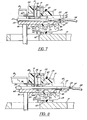
- FIGURE 7 illustrates the strip mode of the assembly unit wherein there will be a continued forward movement of stripping cam 42 as well as push rod 57.
- FIGURE 8 shows the eject mode of the assembly apparatus. The continued movement of the push rod 57 will cause the assembled commodity 53 to be ejected from the assembly unit and drop down into a suitable receptacle or aperture such as 70 (see FIGURE 1).
- the jaws 38, 39 and 40 can be radially expanded or separated to a larger extent as indicated in FIGURE 8 through the placement of plates such as 63 for engagement with the forward cam rollers 49, 51 and 52.
- the apparatus of this invention is susceptible of placing tubing 54 on a commodity 53 which could be used as a reseal unit in an I.V. administration set with a placement of a reseal cap 110 over the end thereof. Due to the fact that stripper cam 42 has an opening 41 at the top thereof, it can accommodate I.V. administration component devices of various configurations such as a Y-seal unit 67 with a lateral extension 11.
- An important feature of the assembly apparatus 12 or 13 is the fact that the jaws 38, 39 and 40 assume a parallel position as they expand the tubing. This creates a uniform stretching of the tubing along the length of the portion that it is stretched. It will be appreciated that conventional methods stretch tubing for placement over a connecting section wherein the outward portion is stretched to a greater degree than the inner portion as normally happens when a duck-bill type device would be used similar to the jaws on a pair of pliers. The uniform stretching effected by this invention assures a rigid connection as well as one that can be repeated with a larger number of parts. The connection provided by the apparatus of this invention will survive a higher test than conventional solvent bonding.
- Another important feature in addition to the parallel action of the jaw members is the stripping action of the commodity from the apparatus once the tubing has been assembled thereon. It will be appreciated that the central feeding feature permits a high speed and semiautomatic device. The stripping is accomplished by the simultaneous forward motion of both the push rod 57 and the stripping cam 42.
- polyvinylchloride or polyurethane tubing is the preferred composition of the tubing which is utilized. It will be appreciated that other types of flexible tubing including rubber and other plastics suitable for I.V. tubing could be employed.
- the commodities 53 and 67 are formed with a housing which is fabricated from a resinous plastic material such as A.B.S. or rigid polyvinylchloride.
- the apparatus of this invention will operate as effectively with components made from other materials such as rigid steel. As indicated earlier, various components of a wide variety and geometric configurations and sizes can be accommodated by the present apparatus due to the unique construction and arrangement of the stripper cam.
- an apparatus which can semiautomatically assemble flexible tubing on a rigid commodity member without the use of adhesives or solvents.
- the apparatus employs a unique action of the jaw members as well as a stripper cam to result in the uniform stretching of the tubing as well as removable from the stretching jaws in a fast and efficient manner.
- the apparatus is of a durable construction thus assuring a long life and dependable use.
Landscapes
- Engineering & Computer Science (AREA)
- Mechanical Engineering (AREA)
- Automatic Assembly (AREA)
Applications Claiming Priority (2)
| Application Number | Priority Date | Filing Date | Title |
|---|---|---|---|
| US35814682A | 1982-03-15 | 1982-03-15 | |
| US358146 | 1982-03-15 |
Publications (1)
| Publication Number | Publication Date |
|---|---|
| EP0088872A2 true EP0088872A2 (fr) | 1983-09-21 |
Family
ID=23408481
Family Applications (1)
| Application Number | Title | Priority Date | Filing Date |
|---|---|---|---|
| EP19830100876 Withdrawn EP0088872A2 (fr) | 1982-03-15 | 1983-01-31 | Assemblage semi-automatique de tubes flexibles à un élément |
Country Status (2)
| Country | Link |
|---|---|
| EP (1) | EP0088872A2 (fr) |
| BR (1) | BR8301053A (fr) |
Cited By (1)
| Publication number | Priority date | Publication date | Assignee | Title |
|---|---|---|---|---|
| CN116710242A (zh) * | 2020-10-28 | 2023-09-05 | 捷普有限公司 | 用于提供o形环夹持器模块的装置、系统和方法 |
-
1983
- 1983-01-31 EP EP19830100876 patent/EP0088872A2/fr not_active Withdrawn
- 1983-03-03 BR BR8301053A patent/BR8301053A/pt unknown
Cited By (1)
| Publication number | Priority date | Publication date | Assignee | Title |
|---|---|---|---|---|
| CN116710242A (zh) * | 2020-10-28 | 2023-09-05 | 捷普有限公司 | 用于提供o形环夹持器模块的装置、系统和方法 |
Also Published As
| Publication number | Publication date |
|---|---|
| BR8301053A (pt) | 1983-11-22 |
Similar Documents
| Publication | Publication Date | Title |
|---|---|---|
| EP0537926B1 (fr) | Outil d'assemblage alimenté par composants placés en série sur une bande | |
| US6290302B1 (en) | Method for manufacturing brushes and brush manufacturing machine applying this method | |
| AU598091B2 (en) | Apparatus for separating bone and flesh of the legs of poultry or part thereof | |
| US4236302A (en) | Electrical contact feeding and attachment apparatus | |
| DE2721344A1 (de) | Vorrichtung zum einsetzen elektronischer bauelemente in eine leiterplatte | |
| GB2139597A (en) | Apparatus for automatically mounting chip type circuit elements on printed circuit boards | |
| US4206539A (en) | Device for bending, crimping, and trimming leads of transistors or similar components | |
| CN112621147B (zh) | 一种汽车配件自动生产线用操作杆姿态调整单元 | |
| EP0088872A2 (fr) | Assemblage semi-automatique de tubes flexibles à un élément | |
| EP0159415A1 (fr) | Dispositif pour prendre, dresser et transférer des boîtes pliantes | |
| CN210824306U (zh) | 一种夹片送料装置 | |
| US2915616A (en) | Wire bender and connector | |
| CN216425882U (zh) | 一种高效全自动上料设备 | |
| EP0131436A2 (fr) | Appareil de dénudage pour dénuder du fil revêtu | |
| US1400002A (en) | Machine for carding snap-fasteners | |
| US4539740A (en) | Inserter device for electronic components | |
| US3112562A (en) | Method of assembling clinch pins | |
| US3591911A (en) | Machine and method for mounting electrical components on a printed circuit board | |
| DD297288A5 (de) | Vorrichtung zum maschinellen aufbringen von dichtungsstopen auf elektrische leitungen | |
| JPH0583449B2 (fr) | ||
| CN209133333U (zh) | 一种磁性元器件自动成型机 | |
| US4271581A (en) | Apparatus for inserting multiple terminals into a holder | |
| DE59392T1 (de) | Tragbare etikettiermaschine. | |
| CN112909707B (zh) | 自动组装装置 | |
| CN109873285B (zh) | 一种切插一体机 |
Legal Events
| Date | Code | Title | Description |
|---|---|---|---|
| PUAI | Public reference made under article 153(3) epc to a published international application that has entered the european phase |
Free format text: ORIGINAL CODE: 0009012 |
|
| AK | Designated contracting states |
Designated state(s): DE FR GB IT |
|
| STAA | Information on the status of an ep patent application or granted ep patent |
Free format text: STATUS: THE APPLICATION HAS BEEN WITHDRAWN |
|
| 18W | Application withdrawn |
Withdrawal date: 19840517 |
|
| RIN1 | Information on inventor provided before grant (corrected) |
Inventor name: ZAHA, JUERGEN HEINZ Inventor name: CHOUDHURY, HRISHIKESH |