EP0087733A1 - Distributor unit for heating and/or cooling systems operating by a heat carrier capable of flowing - Google Patents
Distributor unit for heating and/or cooling systems operating by a heat carrier capable of flowing Download PDFInfo
- Publication number
- EP0087733A1 EP0087733A1 EP83101712A EP83101712A EP0087733A1 EP 0087733 A1 EP0087733 A1 EP 0087733A1 EP 83101712 A EP83101712 A EP 83101712A EP 83101712 A EP83101712 A EP 83101712A EP 0087733 A1 EP0087733 A1 EP 0087733A1
- Authority
- EP
- European Patent Office
- Prior art keywords
- unit according
- distribution unit
- column
- chambers
- distributor
- Prior art date
- Legal status (The legal status is an assumption and is not a legal conclusion. Google has not performed a legal analysis and makes no representation as to the accuracy of the status listed.)
- Granted
Links
- 238000010438 heat treatment Methods 0.000 title claims abstract description 18
- 238000001816 cooling Methods 0.000 title claims abstract description 6
- 238000009413 insulation Methods 0.000 claims abstract description 29
- 238000005192 partition Methods 0.000 claims abstract description 24
- 230000001105 regulatory effect Effects 0.000 claims abstract description 9
- 238000009434 installation Methods 0.000 claims abstract description 5
- 230000009969 flowable effect Effects 0.000 claims abstract description 4
- 238000009826 distribution Methods 0.000 claims description 91
- 238000012546 transfer Methods 0.000 claims description 25
- 238000013461 design Methods 0.000 claims description 7
- 238000011144 upstream manufacturing Methods 0.000 claims description 6
- 230000008878 coupling Effects 0.000 claims description 4
- 238000010168 coupling process Methods 0.000 claims description 4
- 238000005859 coupling reaction Methods 0.000 claims description 4
- 210000002445 nipple Anatomy 0.000 claims description 4
- 239000003507 refrigerant Substances 0.000 claims description 4
- 239000011521 glass Substances 0.000 claims description 3
- 230000000149 penetrating effect Effects 0.000 claims description 3
- 230000009471 action Effects 0.000 claims description 2
- 238000009833 condensation Methods 0.000 claims description 2
- 230000005494 condensation Effects 0.000 claims description 2
- 238000005259 measurement Methods 0.000 claims description 2
- 239000012530 fluid Substances 0.000 claims 1
- 230000036961 partial effect Effects 0.000 description 6
- 238000004519 manufacturing process Methods 0.000 description 5
- 238000000034 method Methods 0.000 description 4
- 230000002829 reductive effect Effects 0.000 description 4
- 230000033228 biological regulation Effects 0.000 description 3
- 238000005266 casting Methods 0.000 description 3
- 238000010276 construction Methods 0.000 description 3
- 230000008569 process Effects 0.000 description 3
- 238000000926 separation method Methods 0.000 description 3
- 230000000694 effects Effects 0.000 description 2
- 238000007789 sealing Methods 0.000 description 2
- 230000007704 transition Effects 0.000 description 2
- 238000009423 ventilation Methods 0.000 description 2
- XLYOFNOQVPJJNP-UHFFFAOYSA-N water Substances O XLYOFNOQVPJJNP-UHFFFAOYSA-N 0.000 description 2
- 230000000712 assembly Effects 0.000 description 1
- 238000000429 assembly Methods 0.000 description 1
- 230000004888 barrier function Effects 0.000 description 1
- 230000008901 benefit Effects 0.000 description 1
- 230000015572 biosynthetic process Effects 0.000 description 1
- 239000003795 chemical substances by application Substances 0.000 description 1
- 238000011161 development Methods 0.000 description 1
- 238000001704 evaporation Methods 0.000 description 1
- 230000017525 heat dissipation Effects 0.000 description 1
- 230000020169 heat generation Effects 0.000 description 1
- 238000003780 insertion Methods 0.000 description 1
- 230000037431 insertion Effects 0.000 description 1
- 239000011810 insulating material Substances 0.000 description 1
- 239000012774 insulation material Substances 0.000 description 1
- 230000001788 irregular Effects 0.000 description 1
- 230000000670 limiting effect Effects 0.000 description 1
- 238000012423 maintenance Methods 0.000 description 1
- 239000000463 material Substances 0.000 description 1
- 230000004048 modification Effects 0.000 description 1
- 238000012986 modification Methods 0.000 description 1
- 238000005086 pumping Methods 0.000 description 1
- 230000009467 reduction Effects 0.000 description 1
- 230000007363 regulatory process Effects 0.000 description 1
- 230000008439 repair process Effects 0.000 description 1
- 230000000717 retained effect Effects 0.000 description 1
- 230000002441 reversible effect Effects 0.000 description 1
- 239000007787 solid Substances 0.000 description 1
- 238000009827 uniform distribution Methods 0.000 description 1
Images


Classifications
-
- F—MECHANICAL ENGINEERING; LIGHTING; HEATING; WEAPONS; BLASTING
- F24—HEATING; RANGES; VENTILATING
- F24D—DOMESTIC- OR SPACE-HEATING SYSTEMS, e.g. CENTRAL HEATING SYSTEMS; DOMESTIC HOT-WATER SUPPLY SYSTEMS; ELEMENTS OR COMPONENTS THEREFOR
- F24D3/00—Hot-water central heating systems
- F24D3/10—Feed-line arrangements, e.g. providing for heat-accumulator tanks, expansion tanks ; Hydraulic components of a central heating system
- F24D3/1058—Feed-line arrangements, e.g. providing for heat-accumulator tanks, expansion tanks ; Hydraulic components of a central heating system disposition of pipes and pipe connections
- F24D3/1066—Distributors for heating liquids
-
- F—MECHANICAL ENGINEERING; LIGHTING; HEATING; WEAPONS; BLASTING
- F24—HEATING; RANGES; VENTILATING
- F24D—DOMESTIC- OR SPACE-HEATING SYSTEMS, e.g. CENTRAL HEATING SYSTEMS; DOMESTIC HOT-WATER SUPPLY SYSTEMS; ELEMENTS OR COMPONENTS THEREFOR
- F24D19/00—Details
- F24D19/10—Arrangement or mounting of control or safety devices
- F24D19/1006—Arrangement or mounting of control or safety devices for water heating systems
- F24D19/1009—Arrangement or mounting of control or safety devices for water heating systems for central heating
Definitions
- Distribution unit for heating and / or cooling systems working with a flowable heat exchange medium for connecting a plurality of branch lines to main flow and return lines, with a plurality of identical or similar distribution elements which are fitted with fittings of a controlled system such as shut-off, throttling, regulating and deflection elements, feed pumps and.
- a controlled system such as shut-off, throttling, regulating and deflection elements, feed pumps and.
- the task of these individual supply and return groups is to supply the medium flowing through, regulated and controlled according to the requirements, to the consumer units.
- thermal systems such as Central heating systems demand that the heat generated be passed on to the heat consumer as quickly as possible and without losses.
- the distributor sticks and the vertical individual groups e.g. in central heating systems in the boiler room, pipe insulation against heat loss must be provided in accordance with the standard.
- the valves, pump bodies, regulator bodies, flanges and sleeves are insulated against heat loss almost exclusively in large systems. In smaller thermal systems, this important insulation is mostly dispensed with for all economic reasons and because of the difficult to install total thermal insulation across all fittings.
- a very essential heat-conducting intermediate element in the form of heat distribution systems is connected between heat generation and heat dissipation, which in known systems does not meet today's requirements for saving thermal energy. It is also not possible to meet the requirements with conventional materials and structures at the construction site.
- the control group of a medium-sized hot water central heating system includes: 2 flow valves, 2 return valves, 1 control valve, 1 circulation pump, a total of 6 valves for each control group.
- each central heating system has two control groups with 12 valve bodies, which lead to a heat loss of 1080 watts / h (with non-insulated valve bodies).
- the object of the invention is to further develop this unit in such a way that the flow processes are economically improved and the losses in thermal energy are substantially reduced with simplified and less expensive production.
- the distributor elements of individual flow circuits are combined to form uniform distributor columns with integrated fittings and at least one flow chamber and one return chamber.
- the entire distribution unit can be designed to be extraordinarily compact with a small volume and a correspondingly small outer surface, and therefore to be insulated from the outside as a whole in a simple manner.
- the heat-emitting surfaces are further reduced by the fact that almost all of the fittings required for the different control and regulating processes are accommodated within the walls of the individual distributor columns, and therefore cannot themselves emit any heat to the outside. It is therefore generally not necessary to pull in any connecting lines between the immediately adjacent column chambers. Since the flow and return chambers directly adjoin each other, only the heat shift necessary anyway in the respective flow circuits occurs by raising the return temperature before it is introduced into the boiler.
- the individual distributors can be almost completely completed by the manufacturing company. They are only to be attached to a bracket, with each other and with theirs To connect external connections. In this way, manufacturing on an industrial basis is made extremely easier and cheaper, and yet it can be adapted to a wide variety of requirements.
- the distribution columns can also be designed so that the flow processes can largely run optimally against low resistances, and the heat transfer volume can be very precisely and economically on the heat generators, consumers and. Vote. Therefore, pumps, regulating and control devices, valves, heat protection and. Dimension particularly economically. As a result of the smaller overall surface, the insulation is simplified overall and the heat losses are reduced.
- the entire unit can be precisely aligned by bumping against the ceiling, so that the pipe connections on the distributor unit and on the building can also be assigned to each other exactly at the specified height. So you can lay it before the unit is delivered and installed. Its manufacture is in turn simplified by the compact arrangement regardless of how it is constructed and controlled.
- the entire unit can easily be provided with a dense, heat-insulating covering and also installed in the building, protected against heat loss.
- thermal insulation can be carried out after the panel has been completed, in principle also at the construction site, but preferably during pre-assembly, and in the last method in particular, it is recommended that the hollow columns be prefabricated, at least on the outer surface of the panel, with a solid wall provided 1Värmedämmlage with openings only for the necessary connection of display and control elements.
- the individual distribution columns which can also be oriented horizontally, can basically be arranged in one piece in a common hollow plate which is divided into individual, adjacent flow channels by numerous partition walls.
- this can result in heat transfers between switched on and switched off circuits.
- the double-chamber hollow columns assigned to each flow circuit are expediently provided at intervals between them and insulated from one another, in particular under thermal insulation layers firmly attached to their side surfaces.
- each distributor column can thus be encased circumferentially with an insulating shell, which reduces the heat emission practically in all directions.
- cross distributors for total flow and return are expediently connected, in particular molded on.
- Such cross distributors can also be prefabricated and, if necessary, connected to corresponding transition openings in the hollow columns with clamp connections, but they can also be formed in one piece.
- Such a cross distributor can be attached at the front end at the upper end and another at the front end at the lower end, that is to say it can be completely classified into the outline shape of a panel.
- the distributor assembly should have at least one main distributor column arranged in its plane along the individual distribution columns for passing through the entire heat transfer medium for all branch lines to be connected. In this way, a presetting or regulation in the entire heating or cooling circuit of the system is possible without this causing significant heat losses or appearing to be disruptive to the outside. Even though the same cross-sections are normally sought for the individual hollow columns and their chambers, it can be done form these chambers within the distribution unit of different widths and thus adapt them to the volume of the flowing media.
- a thermostatically controllable feed pump can be installed in each of the distribution columns, in particular the connecting parts for the drive motor mounted on the outside being led through the front insulation. You can activate the individual flow circuits depending on the heat requirement or influence the temperatures of the flowing media.
- connecting pipe sockets can be led through the insulating sleeve to the outside and preferably surrounded by a molded insulating jacket socket. After the pipe connections have been made, the insulation only needs to be completed at a distance from the hollow column.
- Each distribution column can be assigned heat transfer means for transferring heat from a column chamber, through the level of a partition, into the adjacent column chamber. While this usually made separate, mostly exposed line connections necessary, there is only one easy barrier to overcome. In this way, the return temperature can be raised before it is introduced into the boiler, so that the dew point in the heat generator is not exceeded
- At least one through-opening can be provided between the two column chambers, in particular in the partition, and this can be assigned adjusting means for setting or regulating the flow through this through-opening.
- the passage opening can also be configured as a bypass, in particular channel-shaped, connecting both column chambers with at least one shut-off element, in particular a throttle element.
- Flow guide means for guiding the flow in the column chamber / downstream of the passage opening can also be assigned to the passage opening.
- these guide means for example lamellae, can have guide elements provided in the downstream column chamber upstream of the passage opening and oriented along the column chamber for largely laminar introduction of the main flow and downstream of the passage opening to the longitudinal direction of the column chamber with differently inclined vortex and / or mixer guide elements.
- the two partial flows can be brought together and into each other in the shortest possible way in the desired manner and then mixed thoroughly, so that the possibly under a short distance from the mixing elements and therefore in a matter of seconds. can measure the temperature required for further control processes. In this way, the length of the controlled system or the columns can be shortened.
- the or one further passage opening between the two column chambers is preferably assigned a thermostatically controllable mixing valve which automatically adjusts the guide flow according to a sensed temperature and can optionally be controlled electronically.
- the mixing valve is expediently designed as a multi-way valve which is connected to at least one column chamber by means of two separate connections. In this way, a four-way valve can be fitted in the passage opening and connected to the upstream and downstream parts of both column chambers.
- a separate shut-off device for changing the function can also be assigned to a valve connection as a three-way valve. It is even better to bridge the multi-way valve in a column chamber, in particular the return chamber, by means of a short-circuit connection and to design the shut-off element as a switching element that either blocks the short-circuit connection or the valve connection.
- the walls of the four-way valve can be divided into two pillar chambers by means of the connections thereof, the end parts of the two pillar chambers which are provided at a lateral spacing from one another expediently star-shaped. mig start from the four-way valve.
- At least one distribution column can also have a heat meter with temperature sensors in both column chambers.
- the heat transfer means in divided longitudinal shafts of both chambers of the distributor column, at least in the main distributor column. At least in the divided longitudinal shaft of one of the two column chambers, the or a feed pump can then be attached, which can be connected to its shaft on the suction or pressure side.
- the two longitudinal shafts can also be delimited at one end by a common deflection bend which delimits the opening. It is therefore possible to start a reversing control by switching on the pump, which transfers part of the flow from the flow chamber into the return chamber on a U-shaped loop.
- a mixing device for mixing the shaft flow with the remaining chamber flow should then again be provided, if possible.
- a further embodiment of the invention is characterized by the design of the heat transfer means as thermally connecting the two column chambers, in particular an intermediate partition arranged therebetween, which essentially has a fluid-tight passage and has large heat exchanger surfaces in both longitudinal shafts.
- Such heat transfer means are known per se and do not require any special energy supply in order to improve the heat transfer, but they can be activated by switching on a pump on at least one side, since in this way the heat gradient and thus the heat transfer current is increased. In any case, it is not necessary to divert the heat transfer medium from one chamber to the other, but only to heat it up (or cool it down) through the partition.
- heat transfer elements which, in the manner of "heat pipes", each have a tubular hollow body which is filled with a flowable, rapidly reacting heat exchanger medium or refrigerant, the condensation temperature of which is somewhat above the temperature of the return chamber. A flow then forms in the upper part opposite to the flow in the lower part of the transverse hollow body, the initially vaporous refrigerant condensing in the return chamber, flowing back into the supply chamber and evaporating there again by heating at the higher temperature.
- heat transfer elements include known from "Gesundheits Ingenieur, 1976, pp. 164-167" and need no further explanation.
- the individual distributor columns can be provided with holding rails to be fastened to a supporting wall, in particular through a thermal insulation layer, which are preferably formed by laterally projecting connecting flanges and then, for example, with such a distance from the cor pus of the distributor column can be angled so that they grip around the edge of a thermal insulation layer and hold it.
- thermal insulation layers of adjacent distribution columns can also be spaced apart for an intermediate space for accommodating additional devices such as electrical lines and installation parts. As a rule, these rooms do not have to be stripped, but can simply be closed off with a cover strip to the outside.
- the connecting flanges are expediently formed in a Z-shape with overlapping edge parts. The same screws can then be used for adjacent columns.
- U-shaped guide rails are provided for removable parts of the device, which can be easily and quickly attached and, if necessary, replaced.
- the distribution unit is also adapted to the side of the unit with the same height (or length) and depth, in particular integrated into this, a control and regulation column with individually removable inserts for measurement, control and regulation groups. At least towards the panel, this column can also be shielded by a thermal insulation layer.
- the invention further pursues the task of designing the cross distributor arrangement in such a way that the individual column chambers can be easily connected, and this is done according to the invention primarily in that both cross distributors have flow channels penetrating the distributor columns within their outer surfaces. These flow channels can then be arranged as desired within the distribution columns so that they can be connected to each of the two column chambers can be connected without any special throttling effect. This is relatively easy if you choose different or irregular cross sections, but even with regular cross sections this can be done without any particular difficulty.
- connection openings are provided between each flow channel and at least one column chamber of a distributor column. If it is advisable for manufacturing reasons, such connecting openings can be provided for each of the two chambers, and one of the openings is closed. It is essential, however, that the opening cross-section for the individual flow paths can be adjusted as required for the same chamber volume and thus the respective volume flows can be preset in relation to the expected heating or cooling output.
- the flow channels of the cross distributors can in principle be permanently integrated in the distributor columns, but they are preferably formed by individual pipe elements which can be sealed in the wall of the hollow columns.
- the flow channels a circular cross section, in particular to form them by at least partially cylindrical tube sleeves, regardless of whether such tube sleeves are now welded or soldered to the distributor columns or can be interchangeably sealed in them.
- the wall of the flow channels is expediently provided with a thread on the inside, which can serve various purposes.
- the closure elements can be designed as throttle elements attached to the flow channels, in particular screwed into their walls.
- These can be throttle bushings that can be adjusted in the longitudinal direction or pivotable throttle slides.
- the setting is usually made before assembly, but can also be done subsequently using a nipple wrench or the like if the throttle elements have corresponding inwardly projecting cams.
- the transverse distributors are attached to one and preferably the lower end of the column, it may still be expedient to mount them in the middle of the distributor columns projecting from there towards their outside ends to the connecting lines provided. Practically, this means that two column chambers of different, opposite, protruding columns are connected to a connection point. It must then be decided on a case-by-case basis whether the two column chambers can remain in flow connection or whether at least a limited separation is provided in the area of the cross-distributors, for example in such a way that the distribution columns are subdivided there and the two chambers through separate openings on the same flow channel or connects to different flow channels.
- adjacent chambers can also be selected so that two hollow columns are connected to a common partition. This applies to two flow chambers, but also to the flow and return chambers of the same or a temperature-comparable flow circuit. Either the temperatures in the adjacent chambers are then at least approximately the same, or an influence which is usually sought there is achieved.
- a double panel is formed from individual elongate structural units with a housing box which is in the longitudinal direction through one another intersecting partitions is divided into at least four sub-chambers open on opposite sides. In each such unit, two or four flow circuits can then be connected, ie the width of the panel always remains relatively small.
- cross distributors may only have to be provided in a first panel, partial chambers being connected to subchambers of the other panel arranged in the same way by means of openings in the common partition. So you can also install one cross distributor in the first panel and the other in the second panel.
- a complete interior arrangement of all fittings can only be achieved if you commit yourself to certain fittings. However, due to the extensive technical development, this is not easily possible with some fittings. It may therefore be appropriate there to provide only the necessary connecting means, such as wall openings, pipe sockets or the like, in order to be able to mount the fittings in question on the outside. But it is also important that this external arrangement is only prepared and then optionally carried out as required, d. H. the distributor unit is normally supplied with fittings installed on the inside, but some of these fittings can be replaced during installation or afterwards by other fittings arranged on the outside.
- An external arrangement again increases the heat losses.
- This can be counteracted by a heat-insulating shield covering the space for external fittings.
- This can be a hood that can be fitted as a whole, or isolated side walls of the panel are preferred and the opening is then closed by one or more door elements.
- the one-piece version of the dividing column is sought, it may / may be advisable to make this column at least at one end towards such a length that the fittings in the column chambers are made accessible by lifting off, in particular, a single wall part. You then get by with fewer and easier interruptions in the column chambers. Above all, however, the assembly is simplified, since the fittings can be installed in the housing-fixed or in the removable wall part, depending on the expediency.
- the simplest design of the subdivision is seen in the design of the removable wall part as a front cover, which is preferably attached to a one-piece double tub.
- the distributor columns have at least two housing shells which are formed on opposite sides from a common contact plane and are held against one another in this contact plane.
- This shell design has the particular advantage that you get by with a few, largely prefabricated housing parts and gain greater freedom of movement when attaching the internal fittings to one or the other housing part.
- flow paths such as bypass, through-channels, transverse distributors, their connections and the like are formed in the housing shells designed as cast or shaped bodies. Like. molded in as well as fittings.
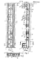
- the distributor assembly shown in FIGS. 1 to 8 is essentially formed from a main distributor column 1, two individual distributor columns 2, 3 and a cross distributor 4 attached to the foot end thereof.
- the distributor columns 1 to 3 are, as is the case with regard to the individual distributor columns 2 , 3 can best be explained with reference to FIGS. 2 to 5, cuboid or square hollow tubes, the body of which has a front wall 5, a rear wall 6 and two side walls 7, 8.
- the distributor columns are divided into two column chambers of the same size, a flow chamber 11 and a return chamber 12.
- the body of the double cross-distributor 4 is divided by a partition 13 into two distributor chambers, an upper flow chamber 14 and a lower return chamber 15. These chambers stand with the chambers of the individual distributor columns, with the flow chambers through openings 16 and with the return chambers through openings 17 in connection.
- the cross distributor 4 can optionally be attached to the lower or upper end of the hollow columns, it is also possible to attach one chamber at the top and the other at the bottom. Instead of attaching the two column chambers 11 and 12 next to one another, they can in principle also be arranged one behind the other, in any case, however, with a greater depth than initially provided.
- the distribution columns 1, 2, 3 can be combined in a manner to be described later to form a closed plate body, a panel, which can be attached as a whole to consoles 18 on a building wall 19 so that the upper end of the panel 20 is flush with the ceiling 21.
- the columns or square tubes can of course also be arranged horizontally and the cross distributor vertically.
- each of the two column chambers 11, 12 there is a shut-off valve 22 at the bottom and a similar shut-off valve 23 at the top.
- a drain support 24 is provided, at the closed upper end, which forms a ventilation chamber or air collection chamber, a ventilation Stub 25.
- a pipe socket 26 protrudes from the front wall just below this for connecting the various lines 27 serving for heat supply and for connection to consumers.
- thermometer 28 is an insertion opening for a thermometer 281, 29 a feed pump arranged in the feed chamber 11 and 30 a check valve arranged in the return chamber 12.
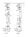
- a first passage opening 31 is provided in the partition 9 below the pumping pump 29 and is associated with an adjusting member 32 that can be preset from the outside by means of a toggle.
- This setting member limits the free opening of the passage opening 31 by means of a cylinder segment 33 and, depending on the setting, also directs a more or less large amount of flow from the return chamber 12 through the passage opening into the flow chamber 11.
- passage opening 31 there is a further passage opening 40 which is equipped with a thermostatically, possibly electronically controllable three or four-way mixing valve 36, the shut-off segment 37 of which in the operating position Fig. 3 off the drain of the return chamber blocks, that is, the entire flow returned in the return chamber leads back into the flow chamber.
- the control can be influenced by in the column, in addition to this or also by remote control devices, in particular from information from the thermometers 281 of both column chambers.
- two longitudinal shafts 39, 41 are divided in the main distributor column 1 by an intermediate wall 38 on the front wall 5 in both column chambers 69, 70 above the opening 311 provided only in the front part.
- the feed pump 291 is arranged only in the longitudinal shaft 39 of the flow chamber 69. Both chambers, like the opening 311, are delimited by a curved deflection bend 42.
- the check valve 301 which is only placed on this part, is also attached and at the outlet end of the shaft a mixing device 60, which in turn effects the mixing of the two partial flows in the return chamber 70.
- the feed pump 291 which acts as an admixing pump for raising the return temperature, which is sometimes necessary, is controlled by a thermostat 67 in the return chamber.
- laterally projecting Z-shaped edge strips 50 are formed on the rear wall 6 of the individual columns, the intermediate web 59 of which has a predetermined distance from the respective side wall 7 or 8, which is the thickness of one on the whole
- the thermal insulation layer 43 which is formed by a U-shaped shell 44 and a plate part 45 which forms on both sides a protruding nose strip 46.
- a positive alignment of the plate part 45 to the column body is achieved. It can also fix the screws gung on the wall or a suitable intermediate support from the flange ends 47 forth.
- the flange edges can be arranged side by side or overlapped.
- the one web 59 can also be dimensioned somewhat shorter than the other.
- One of the two leading edges 46 can be severed at the joint 49.
- a C-shaped holding rail 51 can additionally be fastened, into which various device parts, possibly also an intermediate plate 53, can be attached by means of foot anchors 52, which, for example, shields electrical lines 54 carried up there, while above it, for example, the application of compressed air - Enable control lines or the like 68.
- foot anchors 52 which, for example, shields electrical lines 54 carried up there, while above it, for example, the application of compressed air - Enable control lines or the like 68.
- the space 48 is then closed off from the outside by a strip cover 55.
- a control and regulating column 56 can be inserted laterally next to the panel 20 or also partially integrated therein, in the inserts 57 of which a wide variety of control, measuring and regulating devices can be accommodated. From the column 56, the individual connections to the various hollow columns can then be introduced under, above or in the thermal insulation layer, as required, rooms 48 also being recommended for the upward movement.
- the panel consist of a load-bearing and heat-insulating plastic and are attached to the wall.
- the panel can also be shielded against heat from the brackets 18.
- a thermal insulation layer can also be attached to the end faces and to the outer surfaces of the transverse distributor. All parts of the distributor assembly that conduct the heat transfer medium are stripped on their outer surface.
- the fittings attached within the hollow columns are e.g. T. connected with thin connecting elements through the thermal insulation layer attached to the front wall 5 to the external parts. This also applies to the motor 292 of the pump 29.
- the pipe socket 26 is assigned an outer socket 261, which enables the plugging in of an insulating material sleeve. By bumping the panel against the ceiling, the various connecting lines 27 can also be aligned with the ceiling before the panel is installed.
- the heat transfer tubes 64 are filled with a rapidly reacting heat exchanger agent or refrigerant, which is vaporized in the longitudinal shaft 61 of the flow chamber 69, the steam migrating along the upper wall of the tube to the longitudinal shaft 62 of the return chamber 70 and there kon densifies. After the condensate has returned to the longitudinal shaft 61, the cycle begins again.
- the intensity of the heat transfer can be controlled by simple motor-operated flap valves 65, 66, which inhibit or release the flow in the two longitudinal shafts.
- a feed pump 291 according to FIG. 6 can of course also be used there if the intensity of the heat transfer is to be influenced more strongly.
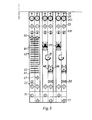
- connection sockets 83 are provided, to which fittings to be attached, for example by means of bends 84, are connected.
- the mixing valve 36 requires a third connection socket 83 for this purpose.
- deflecting bodies 85, 86 are used within the respective partial chambers, of which the deflecting bodies 85 completely shut off the respective column and divert the entire flow through the connection sockets 83 to the outside, while the smaller one Deflector 86 directs only part of the chamber flow to the outside.
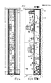
- the two cross-distributors 71, 72 which can be used either as distributors or collectors, are guided below the shut-off valves 22 within the outline of the column chambers across the panel. They form largely cylindrical flow channels 73, 74 by means of individual tube sleeves 75 assigned to each hollow column, which, as can best be seen from FIG. 5, have the same pitch length as the distributor columns 1 to 3. They fit snugly in the manner known from heating element members in nozzle lugs 76 protruding from the outer wall of the distributor columns and are sealed with them to the adjacent distributor column by an interposed ring seal 77.
- bracing are provided with two opposing and inwardly projecting cams 79 nipple sleeves 78, which are provided with opposite external threads at their ends, while the tubular sleeves 75 have opposite internal threads towards their ends.
- cams 79 nipple sleeves 78 which are provided with opposite external threads at their ends, while the tubular sleeves 75 have opposite internal threads towards their ends.
- a centering, rigid connection and, on the other hand, an axial bracing of the tube sleeves 75 and, with them, the distributor columns 1 to 3 are thus achieved.
- the coupling means are not visible from the outside.
- Each tube sleeve 75 has at least one opening 81 which is offset towards one end of the tube sleeve in such a way that it is in the transverse distributor 71 approximately in the middle of the front running chamber 11 and in the reverse arrangement in the transverse distributor 72 comes to lie approximately in the middle of the return chamber 12.
- Each opening 81 is also assigned a throttle bushing 82, which sits with its external thread in the internal thread of the tubular sleeve 75 and can be adjusted in such a way that the free cross section of the opening 81 can be adapted to the size of the volume flow that is to be controlled in the respective flow branch . Since the forward and return flow are the same in every two-flow, the throttle bushings 82 of a hollow column must also be set in the same way. This setting also enables quite different flow circuits to be routed through uniform supply and return chambers. Cams 79 are also fitted on the inside of the throttle bushings 82, which enable adjustment even after assembly.
- the transverse distributor 71 has moved somewhat towards the rear wall 6, the lower-lying transverse distributor 72 towards the front wall 5.
- the heat transfer medium can therefore flow past the transverse distributor 71 largely unhindered in the return chamber 12.
- the ends of the cross distributors 71, 72 can be closed by threaded plugs.
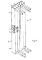
- FIG. 17 shows a schematic spatial representation of two double columns 91, each of which is practically formed by a lower hollow column 92 and an upper hollow column 93, both of which have lines 27 extending from their ends (below and above) and at their central connection point from common cross-distributors 71, 72 are crossed.
- the two columns 92, 93 can be separated from one another by a cross plate or the like and can be provided with separate cross distributors. You can also arrange the cross-distributors 71, 72 so that they cause a separation of the two hollow columns, but this is usually Separation is not necessary. In any case, it is advisable to provide the openings 81 in both transverse distributors at the top and bottom.
- flow medium flows out of the cross distributor 71 through opposite openings 81 into the flow chambers 11 of the two hollow columns 92, 93 arranged one above the other, and the return chambers 12 are connected in the same way to the cross distributor 72.
- the distributor columns can be formed as all-round closed tubes of various cross-sectional shapes, the rear wall 6, side walls 7, 8 and partition 9 are integrated into a longitudinal double trough 90 according to FIG 105 is closed. This makes it possible to provide the built-in fittings either on the lid 105 or on the double tub 90. Assembly, maintenance and repairs are simplified in this way.
- the double trough 190 is rounded at its rear longitudinal edges, and according to FIG. 22 a double trough 290 is formed by two troughs 97, which are partially cylindrically rounded on the rear.
- both pillar chambers 11, 12 being circular and delimited by two double shells 390, 391, which are sealed against one another in a common contact plane and sealed by screws and are formed approximately symmetrically from this contact plane to two semi-cylindrical channels 971.
- the semi-cylindrical grooves can basically merge into one another.
- the channels 971 of the double shells 490, 491 are arranged with a larger spacing and are connected by flanges 100 drawn in between them which are more or less wide.
- the partition elements 109 lie close together, the partition elements 209 according to FIG. 23 smaller and, according to FIG. 24, larger spacing.
- the distributor column 101 shown there is essentially formed by a double-shell housing 104, to which two column-shaped pieces 107 and 108 are fastened by means of double-thread coupling bushings 106.
- the mixing valve 136 designed as a four-way valve, the flow chamber 11 and the return chamber 12 are divided into upstream subchambers 11b and 12a and downstream subchambers 11a and 12b. These subchambers are each connected to the four-way mixing valve 136, they start from it in a star shape.
- a passage 131 used as a bypass with an infinitely adjustable adjusting member 132 now extends between the two lateral subchambers 11a and 12a. In this way, the circulation flow between the two subchambers 11a and 12a in particular can be controlled.
- connection d is bridged by a short-circuit channel 12c drawn between the subchambers 12a and 12b, in which a switching element 118 with its segment in the position shown shows the connection d and in one other position the short-circuit channel. 12c locks.
- the four-way mixing valve 136 can be converted into a three-way mixing valve.
- the heat exchange medium can be simply conducted up there. It becomes more difficult already at the transition from the return sub-chamber 12b to the transverse collector 172 located below.
- the connecting line 119 must therefore, as can be seen above all in FIG. 26, be diverted around the transverse distributor 171.
- a heat meter 120 which is primarily arranged in the return line, determines the flow and return temperature using temperature buttons 121 and, in conjunction with the amount of medium flowing through, records the amount of heat emitted between the two temperature buttons and normally feeds it to a recording device.
- 126 denotes a thermometer
- 127 a pressure gauge connection
- 128 is an emptying nozzle, which can possibly also be equipped with an emptying hook.
- the two housing shells 10, 110 can be braced against one another with sufficient sealing security by the screws 96 attached in different lateral flanges, possibly also by means of screws inserted through the flow paths. It is of course also possible to use a separate clamping frame for this purpose, which extends from the outside to the contact plane 98 acts on the housing shells.
- the individual distributor columns can only be coupled to one another by the nipple sleeves 178 drawn into the transverse distributor 171 and transverse collector 172. They are expediently attached with circumferential spacings in an outer housing 124, the spaces being filled with thermal insulation material. Slidable throttle bushings 182 are also used here at the connections of the column chambers.
Landscapes
- Engineering & Computer Science (AREA)
- Physics & Mathematics (AREA)
- Thermal Sciences (AREA)
- Chemical & Material Sciences (AREA)
- Combustion & Propulsion (AREA)
- Mechanical Engineering (AREA)
- General Engineering & Computer Science (AREA)
- Steam Or Hot-Water Central Heating Systems (AREA)
- Heat-Exchange Devices With Radiators And Conduit Assemblies (AREA)
Abstract
Description
Verteileraggregat für mit einem strömungsfähigen Wärmetauschermedium arbeitende Heizungs- und/oder Kühlanlagen zum Anschluß einer Mehrzahl-Zweigleitungen an Haupt- Vorlauf- und-Rücklaufleitungen, mit einer Mehrzahl gleicher oder gleichartiger Verteilerelemente, die mit Armaturen einer Regelstrecke wie Absperr-, Drossel-, Regel- und Umlenkelemente, Förderpumpen u. dgl. versehen, in Nebeneinanderanordnung paneelartig zusammengefaßt und von einer Wärmeisolierung umgeben sind.Distribution unit for heating and / or cooling systems working with a flowable heat exchange medium for connecting a plurality of branch lines to main flow and return lines, with a plurality of identical or similar distribution elements which are fitted with fittings of a controlled system such as shut-off, throttling, regulating and deflection elements, feed pumps and. Like. Provided, panel-like arrangement in a side-by-side arrangement and surrounded by thermal insulation.
Bei wärmetechnischen Energieversorgungsanlagen durch die ein Medienstrom geleitet wird, werden im allgemeinen zur Teilung dieses Volumenstromes horizontal gelegene, aus einzelnen Rundrohren hergestellte Verteilerstöcke gebaut. Solche horizontal gelegenen Verteilerstöcke dienen der Aufgabe, vorlauf- und rücklaufseitig durchfließende Medien in Einzelgruppen senkrecht nach oben zu teilen. Diese senkrecht zum Verteilerstock angeordneten Einzelgruppen bestehen ebenfalls aus Rundrohren zwischen die durch Gewinde-oder Flansch verbindungen Pumpen, Absperrventile, sowie Steuer-, Meß-, und Reglerkörper eingebaut sind.In the case of thermal energy supply systems through which a media flow is conducted, horizontally located distribution blocks made from individual round tubes are generally built to divide this volume flow. Such horizontally located distributor sticks serve the task of dividing media flowing through on the supply and return sides vertically upwards in individual groups. These individual groups, arranged perpendicular to the distributor stick, also consist of round tubes between which pumps, shut-off valves, as well as control, measuring and regulator bodies are installed by means of threaded or flange connections.
Aufgabe dieser Einzel- Vor- und-Rücklaufgruppen ist es, das hindurchfließende Medium, den Anforderungen entsprechend geregelt und gesteuert, den Verbrauchereinheiten zuzuführen. Bei wärmetechnischen Anlagen wie z.B. Zentralheizungen besteht die Forderung, die erzeugte Wärme möglichst rasch und ohne Verluste an den Wärmeabnehmer weiterzuleiten.The task of these individual supply and return groups is to supply the medium flowing through, regulated and controlled according to the requirements, to the consumer units. In thermal systems such as Central heating systems demand that the heat generated be passed on to the heat consumer as quickly as possible and without losses.
Die Verteilerstöcke und die senkrechten Einzelgruppen, die z.B. bei Zentralheizungsanlagen im Kesselraum untergebracht sind, müssen nach Normvorschrift eine Rohrisolierung gegen Wärmeverluste erhalten. Fast ausschließlich nur in Großanlagen werden hier auch die Ventile, Pumpenkörper, Reglerkörper sowie Flansche und Muffen gegen Wärmeverluste isoliert. Bei kleineren wärmetechnischen Anlagen wird aus wirtschaftlichen Gründen und aus Gründen der schwierig anzubringenden Gesamtwärmedämmung über alle Armaturen hinweg meist auf diese so wichtige Isolierung verzichtet.The distributor sticks and the vertical individual groups, e.g. in central heating systems in the boiler room, pipe insulation against heat loss must be provided in accordance with the standard. The valves, pump bodies, regulator bodies, flanges and sleeves are insulated against heat loss almost exclusively in large systems. In smaller thermal systems, this important insulation is mostly dispensed with for all economic reasons and because of the difficult to install total thermal insulation across all fittings.
Aus den vorbeschriebenen Schwierigkeiten werden heute Wärmeverteilungsanlagen nur rohrseitig, nicht aber - wie das jetzt in der Bundesrepublik Deutschland gesetzlich vorgeschrieben ist - auch ventilkörperseitig isoliert.From the difficulties described above, today heat distribution systems are only insulated on the pipe side, but not - as is now required by law in the Federal Republic of Germany - also on the valve body side.
Zwischen Wärmeerzeugung und Wärmeabgabe ist ein sehr wesentliches wärmeführendes Zwischenglied in Form von Wärmeverteilungsanlagen eingeschaltet, das bei bekannten Anlagen nicht den heutigen Anforderungen zur Einsparung von Wärmeenergie entspricht. Es ist auch nicht möglich, mit herkömmlichen Werkstoffen und Aufbauten an der Baustelle die gestellten Forderungen zu erfüllen.A very essential heat-conducting intermediate element in the form of heat distribution systems is connected between heat generation and heat dissipation, which in known systems does not meet today's requirements for saving thermal energy. It is also not possible to meet the requirements with conventional materials and structures at the construction site.
Um welche Größenordnungen an Gesamtwärmeverlusten es bei diesen Anlagen in Zentralheizungsanlagen geht, zeigen nachfolgende Zahlen:
- In der Bundesrepublik Deutschland werden zur
Zeit - Auf der Basis einer mittleren Warmwasserheizungsvorlauftemperatur von 50°C, über den ganzen Tag gerechnet, und einer Umgebungstemperatur von 20°C, gibt ein nicht isolierter Ventilkörper mit der Nennweite DN 50 ca. 90 Watt pro Stunde an Wärme ab.
- In the Federal Republic of Germany, 4.8 million oil-fired systems are currently being monitored and checked for their exhaust gas losses. If you take this small number of actually operated central heating systems in Germany as a basis, the following picture emerges:
- On the basis of an average hot water heating flow temperature of 50 ° C, calculated over the whole day, and an ambient temperature of 20 ° C, a non-insulated valve body with a nominal diameter of DN 50 emits approx. 90 watts per hour of heat.
In der Regelgruppe einer mittleren Warmwasser-Zentralheizungsanlage sind eingebaut: 2 Vorlaufventile, 2 Rücklaufventile, 1 Regelventil, 1 Umwälzpumpe, insgesamt 6 Ventile für jede Regelgruppe. Im Durchschnitt hat jede Zentralheizungsanlage jedoch zwei Regelgruppen mit 12 Ventilkörpern, die zu einem Wärmeverlust von 1080 Watt/h führen (mit nicht isolierten Ventilkörpern).The control group of a medium-sized hot water central heating system includes: 2 flow valves, 2 return valves, 1 control valve, 1 circulation pump, a total of 6 valves for each control group. On average, however, each central heating system has two control groups with 12 valve bodies, which lead to a heat loss of 1080 watts / h (with non-insulated valve bodies).
Bei einem 24-Stunden-Betrieb ergibt das einen Wärmeverlust von ca. 26.000 Watt h/Tag = 26 kWh/Tag. Sezt man eine Heizperiode von ca. 210 Heiztagen in Rechnung, so ergibt das 26 x 210 = ca. 5460 kWh/Jahr, bei den eingangs erwähnten 4,8 Millionen z. Zt. überwachten Zentralheizungsanlagen ergibt sich so ein Wärmeverlustvolumen von ca. 26,2 Millionen MWh = 26.200 GWh.With 24-hour operation, this results in a heat loss of approx. 26,000 watt hours / day = 26 kWh / day. If you calculate a heating period of approx. 210 heating days, this results in 26 x 210 = approx. 5460 kWh / year, for the 4.8 million z mentioned at the beginning. Central heating systems currently monitored result in a heat loss volume of approx.26.2 million MWh = 26,200 GWh.
Durch die DE-AS 2 014 093 ist es bekannt, ein Verteileraggregat als frei im Raum aufragende Vierkantsäule mit einzelnen paneel-artig ausgebildeten Begrenzungsteilen zu versehen, wobei die Verteilerrohre rechteckförmigen Querschnitt haben und von unten ringförmig angeordneten Querverteilern hochragen. Die Installation ist dort jedoch wieder in herkömmlicher Weise mit ausschließlich außen angeordneten Armaturen ausgeführt, was zu den zuvor beschriebenen Nachteilen führt,From DE-AS 2 014 093 it is known to provide a distributor unit as a square pillar which rises freely in space with individual panel-like limiting parts, the distributor pipes having a rectangular cross section and projecting from above from below annular distributors. However, the installation is again carried out in a conventional manner with fittings arranged exclusively on the outside, as described above leading disadvantages,
Ausgehend von dem eingangs genannten Verteileraggregat liegt der Erfindung die Aufgabe zugrunde, dieses Aggregat so weiterzubilden, daß bei vereinfachter und verbilligter Fertigung die Strömungsvorgänge wirtschaftlich verbessert und die Verluste an Wärmeenergie wesentlich herabgesetzt werden.Starting from the distributor unit mentioned at the outset, the object of the invention is to further develop this unit in such a way that the flow processes are economically improved and the losses in thermal energy are substantially reduced with simplified and less expensive production.
Zur Lösung dieser Aufgabe werden erfindungsgemäß die Verteilerelemente einzelner Strömungskreise zu einheitlichen Verteilersäulen mit integriert eingebauten Armaturen und mindestens einer Vorlaufkammer und einer Rücklaufkammer zusammengefaßt.To achieve this object, the distributor elements of individual flow circuits are combined to form uniform distributor columns with integrated fittings and at least one flow chamber and one return chamber.
Durch die Ausbildung aus einheitlichen Verteilersäulen für die einzelnen Strömungskreise ist das ganze Verteileraggregat außergewöhnlich kompakt mit geringem Volumen und entsprechend kleiner Außenfläche auszuführen, daher auf einfache Weise auch als Ganzes nach außen hin zu isolieren. Die Wärme abgebenden Flächen sind ferner dadurch gemindert, daß nahezu die gesamten für die unterschiedlichen Steuerungs- und Regelvorgänge benötigten Armaturen innerhalb der Wandungen der einzelnen Verteilersäulen untergebracht sind, selbst also keinerlei Wärme nach außen abgeben können. Es sind daher in der Regel auch keine Verbindungsleitungen zwischen die unmittelbar aneinandergrenzenden Säulenkammern einzuziehen. Da Vorlauf- und Rücklaufkammer unmittelbar aneinandergrenzen, tritt dort nur die ohnehin in den jeweiligen Strömungskreisen notwendige Wärmeverschiebung durch Anheben der Rücklauftemperatur vor der Einleitung in den Kessel ein.Due to the formation of uniform distribution columns for the individual flow circuits, the entire distribution unit can be designed to be extraordinarily compact with a small volume and a correspondingly small outer surface, and therefore to be insulated from the outside as a whole in a simple manner. The heat-emitting surfaces are further reduced by the fact that almost all of the fittings required for the different control and regulating processes are accommodated within the walls of the individual distributor columns, and therefore cannot themselves emit any heat to the outside. It is therefore generally not necessary to pull in any connecting lines between the immediately adjacent column chambers. Since the flow and return chambers directly adjoin each other, only the heat shift necessary anyway in the respective flow circuits occurs by raising the return temperature before it is introduced into the boiler.
Die einzelnen Verteiler können praktisch vollständig vom Herstellungsbetrieb fertiggestellt werden. Sie sind nur an einer Halteruung anzubringen, miteinander und mit ihren Außenanschlüssen zu verbinden. Auf diese Weise wird die Herstellung auf industrieller Basis außergewöhnlich vereinfacht und verbilligt, und trotzdem ist eine Anpassung an die unterschiedlichsten Anforderungen möglich. Dabei lassen sich auch die Verteilersäulen so gestalten, daß die Strömungsvorgänge weitgehend optimal gegen geringe Widerstände ablaufen können, und das Wärmeträgervolumen läßt sich sehr genau und wirtschaftlich auf die Wärmeerzeuger, Verbraucher u. dgl. abstimmen. Daher lassen sich auch Pumpen-, Regel- und Steuereinrichtungen, Ventile, Wärmeschutz u. dgl. besonders wirtschaftlich dimensionieren. Infolge geringerer Gesamtoberfläche werden die Isolierungen insgesamt vereinfacht und die Wärmeverluste herabgesetzt.The individual distributors can be almost completely completed by the manufacturing company. They are only to be attached to a bracket, with each other and with theirs To connect external connections. In this way, manufacturing on an industrial basis is made extremely easier and cheaper, and yet it can be adapted to a wide variety of requirements. The distribution columns can also be designed so that the flow processes can largely run optimally against low resistances, and the heat transfer volume can be very precisely and economically on the heat generators, consumers and. Vote. Therefore, pumps, regulating and control devices, valves, heat protection and. Dimension particularly economically. As a result of the smaller overall surface, the insulation is simplified overall and the heat losses are reduced.
Bei der Paneel-Ausführung läßt sich das ganze Aggregat durch Anstoßen an der Decke exakt ausrichten, so daß sich auch die Rohranschlüsse am Verteileraggregat und am Gebäude einander genau in der vorgegebenen Höhe zuordnen lassen. Man kann also bereits verlegen, bevor das Aggregat geliefert und eingebaut ist. Dessen Herstellung wird wiederum durch die kompakte Anordnung unabhängig davon vereinfacht, wie es aufgebaut und gesteuert wird. Man kann das ganze Aggregat leicht mit einer dichten wärmedämmenden Umhüllung versehen und auch gegen Wärmeverluste geschützt im Gebäude einbauen.In the panel version, the entire unit can be precisely aligned by bumping against the ceiling, so that the pipe connections on the distributor unit and on the building can also be assigned to each other exactly at the specified height. So you can lay it before the unit is delivered and installed. Its manufacture is in turn simplified by the compact arrangement regardless of how it is constructed and controlled. The entire unit can easily be provided with a dense, heat-insulating covering and also installed in the building, protected against heat loss.
Die Wärmedämmung kann im Prinzip nach Fertigstellung des Paneels vorgenommen werden, grundsätzlich auch an der Baustelle, vorzugsweise jedoch bei der Vormontage, und gerade bei dem letzten Verfahren empfiehlt es sich, die Hohlsäulen wenigstens an den Paneel-Außenflächen mit einer vorgefertigten, fest an ihrer Wandung angebrachten 1Värmedämmlage mit Durchbrechungen nur für den notwenigen Anschluß von Anzeige- und Bedienungselementen zu versehen.In principle, thermal insulation can be carried out after the panel has been completed, in principle also at the construction site, but preferably during pre-assembly, and in the last method in particular, it is recommended that the hollow columns be prefabricated, at least on the outer surface of the panel, with a solid wall provided 1Värmedämmlage with openings only for the necessary connection of display and control elements.
Die einzelnen Verteilersäulen, die auch waagerecht orientiert sein können, lassen sich grundsätzlich einstückig in eine gemeinsame Hohlplatte einordnen, die durch zahlreiche Trennwände in einzelne, nebeneinanderliegende Strömungskanäle unterteilt ist. Dabei können allerdings Wärmeübertragungen zwischen eingeschalteten und abgeschalteten Stromkreisen entstehen. Aus diesem Grunde werden zweckmäßigerweise die jedem Strömungskreis zugeordneten Doppelkammer-Hohlsäulen unter Zwischenabständen voneinander vorgesehen und gegeneinander, insbesondere unter fest auf ihren Seitenflächen angebrachte Wärmedämmschichten isoliert. Grundsätzlich kann somit jede Verteilersäule umfangsschlüssig mit einer Isolierschale umhüllt sein, welche die Wärmeabgabe praktisch nach allen Richtungen herabsetzt.The individual distribution columns, which can also be oriented horizontally, can basically be arranged in one piece in a common hollow plate which is divided into individual, adjacent flow channels by numerous partition walls. However, this can result in heat transfers between switched on and switched off circuits. For this reason, the double-chamber hollow columns assigned to each flow circuit are expediently provided at intervals between them and insulated from one another, in particular under thermal insulation layers firmly attached to their side surfaces. In principle, each distributor column can thus be encased circumferentially with an insulating shell, which reduces the heat emission practically in all directions.
An Kopf- oder Fußenden der Verteilersäulen werden zweckmäßigerweise Querverteiler für Gesamtvor- und Rücklauf angeschlossen, insbesondere angeformt. Auch derartige Querverteiler lassen sich vorfertigen und ggf. mit Klemmverbindungen an entsprechenden Ubergangsöffnungen in den Hohlsäulen anschließen, sie können aber auch einstückig angeformt sein. Ein solcher Querverteiler kann stirnseitig am oberen, ein anderer stirnseitig am unteren Ende angebracht werden, sich also vollständig in die Umrißform eines Paneels einordnen lassen.At the head or foot ends of the distributor columns, cross distributors for total flow and return are expediently connected, in particular molded on. Such cross distributors can also be prefabricated and, if necessary, connected to corresponding transition openings in the hollow columns with clamp connections, but they can also be formed in one piece. Such a cross distributor can be attached at the front end at the upper end and another at the front end at the lower end, that is to say it can be completely classified into the outline shape of a panel.
Das Verteileraggregat sollte wenigstens eine in seiner Ebene längs der Einzel-Verteilungssäulen angeordnete Haupt- verteilersäule zum Durchleiten des gesamten Wärmeträgermediums für alle anzuschließenden Zweigleitungen aufweisen. Auf diese Weise ist eine Voreinstellung bzw. Einregelung im gesamten Wärme- bzw. Kältekreislauf der Anlage möglich, ohne daß dies bemerkenswerte Wärmeverluste verursacht bzw. nach außen störend in Erscheinung tritt. Wenn auch normalerweise gleiche Querschnitte für die einzelnen Hohlsäulen und deren Kammern angestrebt werden, so lassen sich doch diese Kammern innerhalb des Verteileraggregates unterschiedlich breit ausbilden und damit dem Volumen der strömenden Medien anpassen.The distributor assembly should have at least one main distributor column arranged in its plane along the individual distribution columns for passing through the entire heat transfer medium for all branch lines to be connected. In this way, a presetting or regulation in the entire heating or cooling circuit of the system is possible without this causing significant heat losses or appearing to be disruptive to the outside. Even though the same cross-sections are normally sought for the individual hollow columns and their chambers, it can be done form these chambers within the distribution unit of different widths and thus adapt them to the volume of the flowing media.
In den Verteilersäulen läßt sich jeweils eine thermostatisch steuerbare Förderpumpe anbringen, wobei insbesondere deren Verbindungsteile für den außen angebrachten Antriebsmotor durch die Frontisolierung hindurchgeführt sind. Man kann so die einzelnen Strömungskreise je nach Wärmebedarf aktivieren bzw. die Temperaturen der strömenden Medien beeinflussen.A thermostatically controllable feed pump can be installed in each of the distribution columns, in particular the connecting parts for the drive motor mounted on the outside being led through the front insulation. You can activate the individual flow circuits depending on the heat requirement or influence the temperatures of the flowing media.
Aus der tragenden Wandung der Verteilersäulen lassen sich Anschlußrohrstutzen durch die Isolierhülse nach außen führen und vorzugsweise mit einem angeformten Isoliermantelstutzen umgeben. Man braucht dann nach Herstellen der Rohranschlüsse die Isolierung nur mit Abstand von der Hohlsäule zu vervollständigen.From the load-bearing wall of the distributor columns, connecting pipe sockets can be led through the insulating sleeve to the outside and preferably surrounded by a molded insulating jacket socket. After the pipe connections have been made, the insulation only needs to be completed at a distance from the hollow column.
Jeder Verteilersäule lassen sich Wärmeübertragungsmittel zum übertragen von Wärme von einer Säulenkammer, durch die Ebene einer Trennwand hindurch, in die benachbarte Säulenkammer zuordnen. Während dies normalerweise gesonderte, meist freiliegende Leitungsverbindungen notwendig machte, bleibt hier nur eine einzige, leicht zu überwindende Barriere. Auf diese Weise läßt sich vor allem die Rücklauftemperatur vor Einleitung in den Kessel anheben, damit die Taupunktgrenze im Wärmeerzeuger nicht unterschritten wirdEach distribution column can be assigned heat transfer means for transferring heat from a column chamber, through the level of a partition, into the adjacent column chamber. While this usually made separate, mostly exposed line connections necessary, there is only one easy barrier to overcome. In this way, the return temperature can be raised before it is introduced into the boiler, so that the dew point in the heat generator is not exceeded
Im Einwirkungsbereich der Förderpumpe läßt sich so zwischen beiden Säulenkammern, insbesondere in der Trennwand, wenigstens eine Durchtrittsöffnung vorsehen, und dieser können Stellmittel zur Einstellung oder Regelung der durch diese Durchtrittsöffnung hindurchgeführten Strömung zugeordnet sein.In the area of action of the feed pump, at least one through-opening can be provided between the two column chambers, in particular in the partition, and this can be assigned adjusting means for setting or regulating the flow through this through-opening.
Die Durchtrittsöffnung kann auch als beide Säulenkammern verbindender, insbesondere kanalförmiger Bypass mit wenigstens einem Absperrelement, insbesondere einem Drosselelement ausgebildet sein.The passage opening can also be configured as a bypass, in particular channel-shaped, connecting both column chambers with at least one shut-off element, in particular a throttle element.
Es lassen sich ferner der Durchtrittsöffnung Strömungs- leitmittel zum Leiten der Strömung in der/Durchtrittsöffnung nachgeschalteten Säulenkammer zuordnen. Beispielsweise können diese Leitmittel,etwa Lamellen, in der nachgeschalteten Säulenkammer stromaufwärts der Durchtrittsöffnung vorgesehene, längs der Säulenkammer ausgerichtete Leitelemente zum weitgehend laminaren Einleiten der Hauptströmung und stromabwärts der Durchtrittsöffnung zur Längsrichtung der Säulenkammer unterschiedlich geneigte Wirbel-und/oder Mischer-Leitelemente aufweisen. So lassen sich einmal die beiden Teilströmungen in der jeweils gewünschten Weise auf kürzestem Wege zusammen- und ineinanderführen und dann gründlich mischen, damit man mit nur geringem Abstand von den Mischelementen und daher in Sekundenschnelle schon die u.U. für weitere Regelvorgänge benötigte Temperatur messen kann. Auf diese Weise läßt sich auch die Länge der Regelstrecke bzw. der Säulen verkürzen.Flow guide means for guiding the flow in the column chamber / downstream of the passage opening can also be assigned to the passage opening. For example, these guide means, for example lamellae, can have guide elements provided in the downstream column chamber upstream of the passage opening and oriented along the column chamber for largely laminar introduction of the main flow and downstream of the passage opening to the longitudinal direction of the column chamber with differently inclined vortex and / or mixer guide elements. In this way, the two partial flows can be brought together and into each other in the shortest possible way in the desired manner and then mixed thoroughly, so that the possibly under a short distance from the mixing elements and therefore in a matter of seconds. can measure the temperature required for further control processes. In this way, the length of the controlled system or the columns can be shortened.
Der oder einer weiteren Durchtrittsöffnung zwischen beiden Säulenkammern wird vorzugsweise ein thermostatisch regelbares Mischventil zugeordnet, das die Leitströmung selbsttätig nach einer ertasteten Temperatur einstellt und ggf. elektronisch gesteuert werden kann.The or one further passage opening between the two column chambers is preferably assigned a thermostatically controllable mixing valve which automatically adjusts the guide flow according to a sensed temperature and can optionally be controlled electronically.
Das Mischventil wird zweckmäßigerweise als Mehrwegeventil ausgebildet, das mit wenigstens einer Säulenkammer mittels zweier getrennter Anschlüsse verbunden ist. So läßt sich ein Vierwegeventil in der Durchtrittsöffnung anbringen und jeweils mit den stromaufwärtigen und stromabwärtigen Teilen beider Säulenkammern in Verbindung bringen.The mixing valve is expediently designed as a multi-way valve which is connected to at least one column chamber by means of two separate connections. In this way, a four-way valve can be fitted in the passage opening and connected to the upstream and downstream parts of both column chambers.
Es kann auch einem Ventilanschluß ein gesondertes Absperrorgan zur Funktionsänderung als Dreiwegeventil zugeordnet werden. Besser ist es noch, das Mehrwegeventil in einer Säulenkammer, insbesondere der Rücklaufkammer, durch eine Kurzschlußverbindung zu überbrücken und das Abschaltorgan als Umschaltorgan auszubilden, das wahlweise die Kurzschlußverbindung oder den Ventilanschluß absperrt.A separate shut-off device for changing the function can also be assigned to a valve connection as a three-way valve. It is even better to bridge the multi-way valve in a column chamber, in particular the return chamber, by means of a short-circuit connection and to design the shut-off element as a switching element that either blocks the short-circuit connection or the valve connection.
Die Wandungen des Vierwegeventils können mittels dessen Anschlüsse beide Säulenkammern unterteilen, wobei zweckmäßigerweise die unter seitlichem Zwischenabstand voneinander vorgesehenen Endteile beider Säulenkammern sternför-. mig vom Vierwegeventil ausgehen.The walls of the four-way valve can be divided into two pillar chambers by means of the connections thereof, the end parts of the two pillar chambers which are provided at a lateral spacing from one another expediently star-shaped. mig start from the four-way valve.
Wenigstens eine Verteilersäule kann auch einen Wärmemengenmesser mit Temperaturtastern in beiden Säulekammern aufweisen.At least one distribution column can also have a heat meter with temperature sensors in both column chambers.
Als besonders zweckmäßig hat es sich erwiesen, wenigstens in der Hauptverteilersäule die Wärmeübertragungsmittel in abgeteilten Längsschächten beider Kammern der Verteilersäule anzuordnen. Mindestens in dem abgeteilten Längsschacht einer der beiden Säulenkammern läßt sich dann die bzw. eine Förderpumpe anbringen, die saug- oder druckseitig an ihrem Schacht angeschlossen sein kann.It has proven to be particularly expedient to arrange the heat transfer means in divided longitudinal shafts of both chambers of the distributor column, at least in the main distributor column. At least in the divided longitudinal shaft of one of the two column chambers, the or a feed pump can then be attached, which can be connected to its shaft on the suction or pressure side.
Es lassen sich auch die beiden Längsschächte an einem Ende durch einen die Durchbrechung begrenzenden gemeinsamen Umlenkbogen begrenzen. Man kann daher durch Einschalten der Pumpe eine Umkehrsteuerung in Gang setzen, die auf einer U-förmigen Schleife einen Teil der Strömung aus der Vorlaufkammer in die Rücklaufkammer überführt. Am auslaßseitigen Ende des stromabwärts liegenden Längsschachtes sollte dann möglichst wieder eine Mischeinrichtung zum Durchmischen der Schachtströmung mit der restlichen Kammerströmung vorgesehen sein..The two longitudinal shafts can also be delimited at one end by a common deflection bend which delimits the opening. It is therefore possible to start a reversing control by switching on the pump, which transfers part of the flow from the flow chamber into the return chamber on a U-shaped loop. At the outlet end of the downstream longitudinal shaft, a mixing device for mixing the shaft flow with the remaining chamber flow should then again be provided, if possible.
Eine weitere Ausführungsform der Erfindung ist gekennzeichnet durch die Ausbildung der Wärmeübertragungsmittel als beide Säulenkammern thermisch verbindende, insbesondere eine dazwischen angeordnete Trennwand im'wesentlichen strömungsmitteldicht durchsetzende Wärmeübertragungselemente mit großen Wärmetauscherflächen in beiden Längsschächten. Solche Wärmeübertragungsmittel sind an sich bekannt und bedürfen keiner gesonderten Energiezufuhr, um den Wärmeübergang zu verbessern, sie lassen sich aber durch Einschalten einer Pumpe auf wenigstens einer Seite aktivieren, da auf diese Weise das Wärmegefälle und damit der Wärmedurchgangsstrom vergrößert wird. Man braucht jedenfalls so nicht das Wärmeträgermedium aus der einen Kammer in die andere umzuleiten, sondern nur durch die Trennwand hindurch aufzuheizen (oder abzukühlen).A further embodiment of the invention is characterized by the design of the heat transfer means as thermally connecting the two column chambers, in particular an intermediate partition arranged therebetween, which essentially has a fluid-tight passage and has large heat exchanger surfaces in both longitudinal shafts. Such heat transfer means are known per se and do not require any special energy supply in order to improve the heat transfer, but they can be activated by switching on a pump on at least one side, since in this way the heat gradient and thus the heat transfer current is increased. In any case, it is not necessary to divert the heat transfer medium from one chamber to the other, but only to heat it up (or cool it down) through the partition.
So lassen sich Wärmeübertragungselemente einsetzen, die nach Art von "heat pipes" jeweils einen rohrförmigen Hohlkörper aufweisen, der mit einem strömungsfähigen, schnell reagierenden Wärmetauschermittel bzw. Kältemittel gefüllt ist, dessen Kondensationstemperatur etwas über der Temperatur der Rücklaufkammer liegt. Es bildet sich dann eine Strömung im oberen Teil entgegengesetzt zur Strömung im unteren Teil des querliegenden Hohlkörpers aus, wobei das zunächst dampfförmige Kältemittel in der Rücklaufkammer kondensiert, in die Vorlaufkammer zurückfließt und dort durch Erwärmung bei der höheren Temperatur wieder verdampft. Solche Vorrichtungen sind u.a. bekannt durch "Gesundheits Ingenieur, 1976, S. 164-167" und bedürfen keiner weiteren Erläuterung.It is thus possible to use heat transfer elements which, in the manner of "heat pipes", each have a tubular hollow body which is filled with a flowable, rapidly reacting heat exchanger medium or refrigerant, the condensation temperature of which is somewhat above the temperature of the return chamber. A flow then forms in the upper part opposite to the flow in the lower part of the transverse hollow body, the initially vaporous refrigerant condensing in the return chamber, flowing back into the supply chamber and evaporating there again by heating at the higher temperature. Such devices include known from "Gesundheits Ingenieur, 1976, pp. 164-167" and need no further explanation.
Die einzelnen Verteilersäulen lassen sich mit insbesondere durch eine Wärmedämmschicht hindurch an einer tragenden Wand zu befestigenden Halteschiene versehen, die vorzugsweise durch seitlich vorspringende Anschlußflansche gebildet sind und dann zum Beispiel mit solchem Abstand zum Korpus der Verteilersäule abgewinkelt sein können, daß sie den Rand einer Wärmedämmlage umgreifen und diese halten.The individual distributor columns can be provided with holding rails to be fastened to a supporting wall, in particular through a thermal insulation layer, which are preferably formed by laterally projecting connecting flanges and then, for example, with such a distance from the cor pus of the distributor column can be angled so that they grip around the edge of a thermal insulation layer and hold it.
Es können auch die Wärmedämmlagen benachbarter Verteilersäulen einen Abstand für einen Zwischenraum zur Aufnahme zusätzlicher Einrichtungen wie elektrische Leitungen und Installationsteile haben. Diese Räume müssen in der Regel nicht abisoliert werden, sondern können auf einfache Weise mit einem Deckstreifen nach außen abgeschlosssen sein.The thermal insulation layers of adjacent distribution columns can also be spaced apart for an intermediate space for accommodating additional devices such as electrical lines and installation parts. As a rule, these rooms do not have to be stripped, but can simply be closed off with a cover strip to the outside.
Dabei werden zweckmäßigerweise die Anschlußflansche Z-förmig mit einander übergreifenden Randteilen ausgebildet. Für benachbarte Säulen kann man dann die gleichen Schrauben verwenden. An den Halteschienen bzw. Anschlußflanschen werden insbesondere U-förmige Führungsschienen für herausnehmbar einzufügende Geräteteile vorgesehen, die sich dadurch leicht und schnell befestigen und ggf. auswechseln lassen.The connecting flanges are expediently formed in a Z-shape with overlapping edge parts. The same screws can then be used for adjacent columns. On the holding rails or connecting flanges, in particular U-shaped guide rails are provided for removable parts of the device, which can be easily and quickly attached and, if necessary, replaced.
Dem Verteileraggregat angepaßt ist ferner eine mit gleicher Höhe (bzw. Länge) und Tiefe seitlich an das Aggrgat anschließend, insbesondere in dieses integriert eine Steuer-und Regelsäüle mit einzeln herausnehmbaren Einschüben für Meß-, Steuer- und Regelgruppen. Wenigstens zum Paneel hin kann auch diese Säule durch eine Wärmedämmlage abgeschirmt sein.The distribution unit is also adapted to the side of the unit with the same height (or length) and depth, in particular integrated into this, a control and regulation column with individually removable inserts for measurement, control and regulation groups. At least towards the panel, this column can also be shielded by a thermal insulation layer.
Die Erfindung verfolgt ferner die Aufgabe, die Querverteileranordnung so zu gestalten, daß sich die einzelnen Säulenkammern ohne weiteres anschließen lassen, und dies geschieht erfindungsgemäß vor allem dadurch, daß beide Querverteiler die Verteilersäulen innerhalb deren Außenflächen durchsetzende Strömungskanäle aufweisen. Diese Strömungskanäle lassen sich dann innerhalb der Verteilersäulen nach Belieben so anordnen, daß sie mit jeder der beiden Säulenkammern ohne sonderlichen Drosselungseffekt in Verbindung gebracht werden können. Dies ist verhältnismäßig einfach, wenn man unterschiedliche oder auch unregelmäßige Querschnitte wählt, aber auch bei regelmäßigen Querschnitten läßt sich dies ohne sonderliche Schwierigkeiten bewerkstelligen.The invention further pursues the task of designing the cross distributor arrangement in such a way that the individual column chambers can be easily connected, and this is done according to the invention primarily in that both cross distributors have flow channels penetrating the distributor columns within their outer surfaces. These flow channels can then be arranged as desired within the distribution columns so that they can be connected to each of the two column chambers can be connected without any special throttling effect. This is relatively easy if you choose different or irregular cross sections, but even with regular cross sections this can be done without any particular difficulty.
Nach einem weiteren Erfindungsvorschlag werden verschließbare, insbesondere einstellbare Verbindungsöffnungen zwischen jedem Strömungskanal und wenigstens einer Säulenkammer einer Verteilersäule vorgesehen. Wenn es sich aus Fertigungsgründen empfiehlt, können solche Verbindungsöffnungen zu jeder der beiden Kammern vorgesehen werden, und eine der Öffnungen wird verschlossen. Wesentlich ist aber vor allem, daß man bei gleichem Kammervolumen den Offnungsquerschnitt für die einzelnen Strömungswege nach Bedarf einstellen und damit eine Voreinstellung der jeweiligen Volumenströme in Bezug auf die erwartete Heiz-oder Kühlleistung vornehmen kann.According to a further proposal of the invention, closable, in particular adjustable, connection openings are provided between each flow channel and at least one column chamber of a distributor column. If it is advisable for manufacturing reasons, such connecting openings can be provided for each of the two chambers, and one of the openings is closed. It is essential, however, that the opening cross-section for the individual flow paths can be adjusted as required for the same chamber volume and thus the respective volume flows can be preset in relation to the expected heating or cooling output.
Die Strömungskanäle der Querverteiler können grundsätzlich in den Verteilersäulen fest integriert sein, sie werden aber bevorzugt durch einzelne abdichtbar in der Wandung der Hohlsäulen angebrachte Rohrelemente gebildet.The flow channels of the cross distributors can in principle be permanently integrated in the distributor columns, but they are preferably formed by individual pipe elements which can be sealed in the wall of the hollow columns.
In der Regel ist es ratsam den Strömungskanälen kreisförmigen Querschnitt zu geben, sie insbesondere durch wenigstens teilweise zylindrische Rohrhülsen zu bilden, unabhängig davon, ob nun solche Rohrhülsen fest mit den Verteilersäulen verschweißt oder verlötet sind oder sich auswechselbar abdichtend in diesen anbringen lassen.As a rule, it is advisable to give the flow channels a circular cross section, in particular to form them by at least partially cylindrical tube sleeves, regardless of whether such tube sleeves are now welded or soldered to the distributor columns or can be interchangeably sealed in them.
Die Wandung der Strömungskanäle wird zweckmäßigerweise innen mit Gewinde versehen, das verschiedenen Zwecken dienen kann.The wall of the flow channels is expediently provided with a thread on the inside, which can serve various purposes.
So können die Verschlußelemente als in den Strömungskanälen angebrachte, insbesondere in deren Wandung eingeschraubte Drosselelemente ausgebildet sein. Dabei kann es sich um in Längsrichtung einstellbare Drosselbuchsen oder schwenkbare Drosselschieber handeln. Die Einstellung wird dabei in der Regel vor der Montage erfolgen, kann aber ggf. auch nachträglich durch Nippelschlüssel o. dgl. geschehen, wenn die Drosselelemente entsprechende nach innen ragende Nocken aufweisen.Thus, the closure elements can be designed as throttle elements attached to the flow channels, in particular screwed into their walls. These can be throttle bushings that can be adjusted in the longitudinal direction or pivotable throttle slides. The setting is usually made before assembly, but can also be done subsequently using a nipple wrench or the like if the throttle elements have corresponding inwardly projecting cams.
Es lassen sich auch die Strömungskanäle der einzelnen Verteilersäulen an ihren Enden mit gegensinnigem Innengewinde versehen und durch mit gegensinnigem Außengewinde versehene buchsenförmige Kupplungsmittel zusammenschließen. Auf diese Weise lassen sich dann auch die einzelnen Verteilersäulen insbesondere über zwischengeschaltete Dichtungsringe gegeneinander verspannen und abdichten.It is also possible to provide the flow channels of the individual distributor columns with opposite internal threads at their ends and to connect them by means of socket-shaped coupling means provided with opposite external threads. In this way, the individual distributor columns can then be braced and sealed against one another, in particular via interposed sealing rings.
Wenn auch in der Regel die Querverteiler an einem und vorzugsweise dem unteren Säulenende angebracht sind, so kann es doch zweckmäßig sein, sie in der Mitte der von dort nach ihren beiden Enden zu den außen vorgesehenen Anschlußleitungen wegragenden Verteilersäulen anzubringen. Praktisch heißt das, daß man an einer Anschlußstelle jeweils zwei Säulenkammern unterschiedlicher, entgegengesetzt wegragender Säulen anschließt. Von Fall zu Fall muß dann entschieden werden, ob die beiden Säulenkammern in Strömungsverbindung bleiben können oder man im Bereich der Querverteiler eine wenigstens begrenzte Trennung vorsieht, etwa dergestalt, daß man dort die Verteilersäulen querunterteilt und die beiden Kammern durch getrennte Öffnungen an den gleichen Strömungskanal oder an unterschiedliche Strömungskanäle anschließt.If, as a rule, the transverse distributors are attached to one and preferably the lower end of the column, it may still be expedient to mount them in the middle of the distributor columns projecting from there towards their outside ends to the connecting lines provided. Practically, this means that two column chambers of different, opposite, protruding columns are connected to a connection point. It must then be decided on a case-by-case basis whether the two column chambers can remain in flow connection or whether at least a limited separation is provided in the area of the cross-distributors, for example in such a way that the distribution columns are subdivided there and the two chambers through separate openings on the same flow channel or connects to different flow channels.
Ob man nun solche Doppelsäulen oder einfache Hohlsäulen verwendet, im Prinzip können immer mehrere, insbesondere je zwei Einzel-Verteilerkammern hintereinander angeordnet sein, Das bereitet natürlich Schwierigkeiten, wenn das Aggregat nur von einer Seite her zugängig ist, weil man dann durch eine Kammer hindurch oder an dieser vorbei nach hinten eingreifen müßte, sofern mehr als zwei Teilkammern nicht nebeneinander zu liegen kommen. In einem solchen Fall empfiehlt es sich daher, zwei Paneele rückseitig aneinander von entgegengesetzten Seiten zugängig anzuordnen, insbesondere seitlich an eine Gebäudewand anzufügen. Man baut dann zwar etwa von der Gebäudewand in den Raum hinein, aber dabei handelt es sich vor allem dann, wenn man Doppelsäulen verwendet, um verhältnismäßig wenige Kammern, die kaum mehr Raum von der Wand aus benötigen als die von vorn zugängigen Kammern. Man kann die vom Aggregat ausgehenden Leitungen ohne Umlenkung in unterschiedlichen Richtungen weiterführen und das Aggregat so abschirmen, daß es weniger störend wirkt. Durch die kompakte Anordnung werden Wärmeverluste weiter gemindert, und die Isolation kann durch zusätzliche überdeckung leicht verbessert werden.Whether you have such double columns or simple hollow columns In principle, several, in particular two individual distribution chambers can always be arranged one behind the other. Of course, this creates difficulties if the unit is only accessible from one side, because one would then have to intervene through or past a chamber, provided that more than two subchambers do not come next to each other. In such a case, it is therefore advisable to arrange two panels on the rear side, accessible from opposite sides, in particular to attach them to the side of a building wall. One builds into the room from the building wall, for example, but especially when using double columns, these are relatively few chambers that hardly need more space from the wall than the chambers accessible from the front. You can continue the lines coming from the unit without deflection in different directions and shield the unit so that it is less disruptive. The compact arrangement further reduces heat losses and the insulation can be easily improved by additional cover.
Es lassen sich auch bei Doppelpaneel-Anordnung benachbarte Kammern so auswählen, daß.sich zwei Hohlsäulen an eine gemeinsame Zwischenwand anschließen. Dies gilt einmal für zwei Vorlaufkammern, aber auch für Vor- und Rücklaufkammer des gleichen oder eines temperaturmäßig vergleichbaren Strömungskreises. Entweder sind dann die Temperaturen in den benachbarten Kammern wenigstens angenähert gleich, oder es wird eine dort ohnehin meist angestrebte Beeinflussung erzielt.In the case of a double panel arrangement, adjacent chambers can also be selected so that two hollow columns are connected to a common partition. This applies to two flow chambers, but also to the flow and return chambers of the same or a temperature-comparable flow circuit. Either the temperatures in the adjacent chambers are then at least approximately the same, or an influence which is usually sought there is achieved.
Nach einem weiteren Erfindungsvorschlag wird ein Doppelpaneel aus einzelnen langgestreckten Baueinheiten mit einem Gehäusekasten gebildet, der in Längsrichtung durch einander kreuzende Zwischenwände unterteilt ist in wenigstens vier nach entgegengesetzten Seiten geöffnete Teilkammern. In jeder solchen Baueinheit lassen sich dann wengistens zwei bzw. vier Strömungskreise anschließen d. h. die Breite des Paneels bleibt stets verhältnismäßig klein.According to a further proposal of the invention, a double panel is formed from individual elongate structural units with a housing box which is in the longitudinal direction through one another intersecting partitions is divided into at least four sub-chambers open on opposite sides. In each such unit, two or four flow circuits can then be connected, ie the width of the panel always remains relatively small.
Unabhängig davon, wieviele solcher Einzelsäulen oder Baueinheiten man aneinanderfügt, müssen gesonderte Querverteiler ggf. nur in einem ersten Paneel vorgesehen werden, wobei Teilkammern mit gleichliegend angeordneten Teilkammern des anderen Paneels mittels Durchbrechungen in der gemeinsamen Zwischenwand verbunden sind. So kann man auch einen Querverteiler im ersten Paneel und den anderen im zweiten Paneel anbringen.Regardless of how many such individual columns or structural units are joined together, separate cross distributors may only have to be provided in a first panel, partial chambers being connected to subchambers of the other panel arranged in the same way by means of openings in the common partition. So you can also install one cross distributor in the first panel and the other in the second panel.
Dies gilt vor allem für den Fall, daß in einer ersten Paneelebene aussschließlich Vorlaufkammern und in einer zweiten Paneelebene nur Rücklaufkammern vorgesehen sind, weil insbesondere die Kammern eines Strömungskreises jeweils entgegengesetzt zueinander angeordnet sind. Anstatt gesonderte Querverteilerelemente vorzusehen, genügt es in diesem Fall, jeweils die Außenwände bzw. Trennwände in den beiden Paneelen an der vorgegebenen Stelle zu durchbrechen. Bei sorgfältiger Einteilung kann man gar das ganze Gehäuse des Verteileraggregates einstückig ausbilden, wenn man jeweils die Rücklaufkammern mit vergleichbarer Rücklauftemperatur nebeneinander anordnet.This applies in particular to the case where only flow chambers are provided in a first panel level and only return chambers are provided in a second panel level, because in particular the chambers of a flow circuit are arranged opposite each other. Instead of providing separate transverse distributor elements, it is sufficient in this case to break through the outer walls or partition walls in the two panels at the predetermined point. With careful division, the entire housing of the distributor unit can even be formed in one piece if the return chambers with a comparable return temperature are arranged side by side.
Während man vornehmlich den integrierten Einbau der Armaturen anstrebt, kann es mitunter auch zweckmäßig sein, einzelne Armaturen, insbesondere wahlweise, außerhalb der Verteilersäulen an diesen anzubringen und an die Säulenkammern durch in oder an der Kammerwand vorgesehene Verbindungsmittel anzuschließen.While the primary aim is to integrate the fittings, it may also be expedient to attach individual fittings, in particular optionally, to the outside of the distributor columns and to connect them to the column chambers by connecting means provided in or on the chamber wall.
Eine vollständige Innenanordnung sämtlicher Armaturen läßt sich nämlich nur dann erreichen, wenn man sich auf bestimmte Armaturenfabrikate festlegt. Dies ist aber bei etlichen Armaturen schon wegen der weitgehenden technischen Entwicklung nicht ohne weiteres möglich. Dort kann es daher angebracht sein, lediglich die notwendigen Verbindungsmittel wie Wanddurchbrechungen, Rohrstutzen o. dgl. vorzusehen, um die faglichen Armaturen außen anbringen zu können. Wesentlich ist aber auch dabei, daß diese Außenanordnung nur vorbereitet und dann nach Bedarf wahlweise vorgenommen wird, d. h. das Verteileraggregat wird normalerweise mit innen eingebauten Armaturen geliefert, aber einzelne dieser Armaturen können schon bei der Montage oder auch nachträglich durch andere außen angeordnete Armaturen ersetzt werden.A complete interior arrangement of all fittings can only be achieved if you commit yourself to certain fittings. However, due to the extensive technical development, this is not easily possible with some fittings. It may therefore be appropriate there to provide only the necessary connecting means, such as wall openings, pipe sockets or the like, in order to be able to mount the fittings in question on the outside. But it is also important that this external arrangement is only prepared and then optionally carried out as required, d. H. the distributor unit is normally supplied with fittings installed on the inside, but some of these fittings can be replaced during installation or afterwards by other fittings arranged on the outside.
Dabei kann es zweckmäßig sein, innerhalb der Säulenkammern im Bereich der Verbindungsmittel Strömungsumlenker anzubringen, die den Durchfluß innerhalb der Säulenkammern ganz oder teilweise unterbinden und die Strömung zu einer nach außen führenden öffnung hin und von einer solchen Öffnung wieder in die Kammer zurücklenken.It can be expedient to install flow deflectors within the column chambers in the area of the connecting means, which completely or partially prevent the flow within the column chambers and direct the flow towards an opening leading to the outside and back into the chamber from such an opening.
Eine Außenanordnung bringt wieder eine Steigerung der Wärmeverluste. Dem kann eine den Raum für Außenarmaturen überdeckende wärmeisolierende Abschirmung entgegenwirken. Dabei kann es sich um eine als Ganzes aufsetzbare Haube handeln, oder es werden isoliete Seitenwände des Paneels vorgezogen und dann die öffnung durch eine oder mehrere Türelemente verschlossen. Hier kann es sich empfehlen, die Abschirmung mit wenigstens einigen Flächenelenenten aus Isolierglas zu versehen, um wenigstens die Anzeigelemente u. ggf. die Einstellorgane von außen sichtbar zu halten.An external arrangement again increases the heat losses. This can be counteracted by a heat-insulating shield covering the space for external fittings. This can be a hood that can be fitted as a whole, or isolated side walls of the panel are preferred and the opening is then closed by one or more door elements. Here it may be advisable to provide the shielding with at least some flat elements made of insulating glass in order to at least u. if necessary, to keep the setting elements visible from the outside.
Wenn auch im Prinzip die einstückige Ausführung der Ver- teilersäule angestrebt wird, so kann/doch zweckmäßig sein, diese Säule wenigstens zu einem Ende hin derart längsunterteilt auszuführen, daß durch Abheben insbesondere eines einzigen Wandungsteiles die Armaturen in den Säulenkammern zugängig gemacht werden. Man kommt dann mit weniger und einfacheren Unterbrechungen in den Säulenkammern aus. Vor allem aber wird die Montage vereinfacht, da man die Armaturen je nach Zweckmäßigkeit im gehäusefesten oder im abnehmbaren Wandungsteil anbringen kann. Die einfachste Ausführung der Unterteilung wird in der Ausbildung des abhebbaren Wandungsteiles als Frontdeckel gesehen, der vorzugsweise auf einer einstückigen Doppelwanne angebracht ist.Although in principle the one-piece version of the dividing column is sought, it may / may be advisable to make this column at least at one end towards such a length that the fittings in the column chambers are made accessible by lifting off, in particular, a single wall part. You then get by with fewer and easier interruptions in the column chambers. Above all, however, the assembly is simplified, since the fittings can be installed in the housing-fixed or in the removable wall part, depending on the expediency. The simplest design of the subdivision is seen in the design of the removable wall part as a front cover, which is preferably attached to a one-piece double tub.
Bei einer derzeit bevorzugten Ausführungsform weisen jedoch die Verteilersäulen wenigstens zwei aus einer gemeinsamen Anlageebene nach entgegengesetzten Seiten ausgeformte und in dieser Anlageebene abdichtend gegeneinandergehaltene Gehäuseschalen auf. Diese Schalenausführung hat den besonderen Vorteil, daß man mit wenigen, weitgehend vorgefertigten Gehäuseteilen auskommt und größere Freizügigkeit im Anbringen der inneren Armaturen am einen oder anderen Gehäuseteil gewinnt.In a presently preferred embodiment, however, the distributor columns have at least two housing shells which are formed on opposite sides from a common contact plane and are held against one another in this contact plane. This shell design has the particular advantage that you get by with a few, largely prefabricated housing parts and gain greater freedom of movement when attaching the internal fittings to one or the other housing part.
Zweckmäßigerweise werden in die als Guß- bzw. Formkörper ausgebildeten Gehäuseschalen Strömungswege wie Bypass, Durchtrittkanäle, Querverteiler, dessen Anschlüsse u. dgl. ebenso eingeformt wie Armaturenaufnahmen.Advantageously, flow paths such as bypass, through-channels, transverse distributors, their connections and the like are formed in the housing shells designed as cast or shaped bodies. Like. molded in as well as fittings.
Da die Verteilersäulen verhältnismäßig lang sind, die Kosten von Gußteilen aber mit der Länge steigen und die wesentlichen Armaturen sich meist zu einem Ende der Verteilersäulen hin anordnen lassen, kann es zweckmäßig sein, die auf diesen Teil beschränkten Gehäuseschalen mit zwei * Endstutzen für den Anschluß einzelnerfals Fortsetzung der *Säulenformstücke Säulenkammern zu versehen.Since the distribution columns are relatively long, but the costs of castings increase with length and the essential fittings can usually be arranged at one end of the distribution columns, it may be advisable to restrict the housing shells to two parts with two * end connections for the connection of individual cases Continuation of the * column fittings To provide column chambers.
In der die Erfindung beispielsweise wiedergebenen Zeichnung zeigen
- Fig. 1 eine räumliche Ansicht eines erfindungsgemäßen Verteileraggregates mit zum oberen Ende hin geschnittenen Hohlsäulen,
- Fig. 2 einen Schnitt durch eine solche Hohlsäule längs der Linie II/II in Fig. 1,
- Fig. 3 einen Schnitt durch diese Säule nach der Linie III/III in Fig. 2,
- Fig. 4 einen Schnitt durch zwei benachbarte Hohlsäulen gemäß Linie IV/IV in Fig. 2,
- Fig. 5 in vergrößertem Maßstab die Stelle V aus Fig.4,
- Fig. 6 eine schematische Frontansicht des Verteileraggregates, teilweise dicht unter den Frontplatten geschnitten,
- Fig. 7 einen Schnitt durch dieses Verteileraggregat nach der Linie VII/VII in Fig. 6,
- Fig. 8 einen solchen Schnitt nach der Linie VIII/VIII in Fig. 6,
- Fig. 9 eine der Fig. 6 entsprechende Darstellung eines im Bereich der Hauptverteilersäulen abgewandelten Verteileraggregates, die
- Fig. 10
und 11 den Fig. 7 und 8 entsprechende Darstellungen dieser Abwandlung, - Fig. 12 eine der Fig. 1 entsprechende räumliche Ansicht eines abgewandelten Verteileraggregates,
- Fig. 13 einen Schnitt durch eine Verteilersäule längs der Linie XIII/XIII in Fig. 12,
- Fig. 14 einen Schnitt durch diese Säule nach der Linie XIV/XIV in Fig. 13,
- Fig. 15 einen dem unteren Teil der Fig. 13 entsprechenden vergrößerten Teilschnitt nach der Linie XV/ XV in Fig. 16,
- Fig.16 einen Teilschnitt nach der Linie XVI/XVI in Fig. 15,
- Fig.17 eine räumliche Prinzipdarstellung eines Paneels mit in der Mitte zwischen zwei äusseren Säulenteilen angebrachten Querverteilern,
- Fig. 18 eine schematische räumliche Darstellung eines im Raum oder an einer Wand freistehend angeordneten Verteileraggregates mit Doppelsäulen und
- Fig. 19 einen Schnitt durch dieses Verteileraggregat nach der Linie XIX/XIX in Fig. 18,
- die Fig. 20
bis 22 Querschnitte durch als Doppelwannen mit Deckel ausgeführte Verteilersäulen, - die Fig. 23 und 24 entsprechende Querschnitte durch zwei Verteilersäulen mit nach entgegengesetzten Seiten ausgewölbten Gehäuseschalen,
- Fig. 25 einen Schnitt durch die Teilungsebene einer speziellen Verteilersäule, deren wesentlicher Teil durch zwei Gehäuseschalen gebildet ist,
- Fig. 26 eine Seitenansicht des Gußteiles einer solchen Verteilersäule rechts in Fig. 25 gesehen und
- Fig. 27 einen Querschnitt der Verteilersäule nach der Linie XXVII in Fig. 25.
- 1 is a perspective view of a distribution unit according to the invention with hollow columns cut towards the upper end,
- 2 shows a section through such a hollow column along the line II / II in FIG. 1,
- 3 shows a section through this column along the line III / III in FIG. 2,
- 4 shows a section through two adjacent hollow columns according to line IV / IV in FIG. 2,
- 5 shows the location V from FIG. 4 on an enlarged scale,
- 6 is a schematic front view of the distribution unit, partially cut close to the front panels,
- 7 shows a section through this distributor unit along the line VII / VII in FIG. 6,
- 8 shows such a section along the line VIII / VIII in FIG. 6,
- FIG. 9 shows a representation corresponding to FIG. 6 of a distributor unit modified in the area of the main distributor columns
- 10 and 11 of FIGS. 7 and 8 corresponding representations of this modification,
- 12 is a spatial view corresponding to FIG. 1 of a modified distribution unit,
- 13 shows a section through a distributor column along the line XIII / XIII in FIG. 12,
- 14 shows a section through this column along the line XIV / XIV in FIG. 13,
- 15 shows an enlarged partial section corresponding to the lower part of FIG. 13 along the line XV / XV in FIG. 16,
- 16 shows a partial section along the line XVI / XVI in FIG. 15,
- 17 shows a basic spatial representation of a panel with transverse distributors attached in the middle between two outer column parts,
- Fig. 18 is a schematic spatial representation of a distribution unit with double columns and arranged freestanding in the room or on a wall
- 19 shows a section through this distribution unit according to the line XIX / XIX in FIG. 18,
- 20 to 22 cross sections through distributor columns designed as double trays with covers,
- 23 and 24 corresponding cross sections through two distribution columns with bulging housing shells on opposite sides,
- 25 shows a section through the parting plane of a special distributor column, the essential part of which is formed by two housing shells,
- Fig. 26 is a side view of the casting of such a distribution column seen on the right in Fig. 25 and
- 27 shows a cross section of the distributor column along the line XXVII in FIG. 25.
Das in den Fig. 1 bis 8 gezeigte Verteileraggregat ist im wesentlichen gebildet aus einer Hauptverteilersäule 1, zwei Einzel-Verteilersäulen 2, 3 und einem an deren Fußende angebrachten Querverteiler 4. Die Verteilersäulen 1 bis 3 sind, wie sich hinsichtlich der Einzel-Verteilersäulen 2, 3 am besten anhand den Fig. 2 bis 5 erläutern läßt, quaderförmig bzw. als Vierkant-Hohlrohre ausgebildet, deren Korpus eine Vorderwand 5, eine Rückwand 6 und zwei Seitenwände 7, 8 aufweist. Durch eine längs im Säulenkorpus eingezogene Trennwand 9 werden die Verteilersäulen unterteilt in zwei gleichgroße Säulenkammern, eine Vorlaufkammer 11 und eine Rücklaufkammer 12.The distributor assembly shown in FIGS. 1 to 8 is essentially formed from a
In gleicher Weise ist der Korpus des Doppel-Querverteilers 4 durch eine Trennwand 13 unterteilt in zwei Verteilerkammern, eine obere Vorlaufkammer 14 und eine untere Rücklaufkammer 15. Diese Kammern stehen mit den Kammern der einzelnen Verteilersäulen, mit den Vorlaufkammern durch üffnungen 16 und mit den Rücklaufkammern durch Öffnungen 17 in Verbindung.In the same way, the body of the
Der Querverteiler 4 kann wahlweise am unteren oder oberen Ende der Hohlsäulen angebracht sein, es läßt sich auch eine Kammer oben, die andere unten anbringen. Anstatt die beiden Säulenkammern 11 und 12 nebeneinander anzubringen, lassen sie sich grundsätzlich auch hintereinander anordnen, jedenfalls aber mit größerer Tiefe ausbilden als zunächst vorgesehen.The
Vom Querverteiler 4 einmal abgesehen, können jedenfalls die Verteilersäulen 1, 2, 3 in später noch zu beschreibender Weise zu einem geschlossenen Plattenkörper, einem Paneel, zusammengefaßt werden, das sich als Ganzes etwa auf Konsolen 18 so an einer Gebäudewand 19 anbringen läßt, daß das obere Ende des Paneels 20 mit der Raumdecke 21 bündig abschließt. Im Prinzip können natürlich auch die Säulen bzw. Vierkantrohre waagerecht und der Querverteiler senkrecht angeordnet werden.Apart from the
In jeder der beiden Säulenkammern 11, 12 ist jeweils unten ein Absperrventil 22, oben ein ebensolches Absperrventil 23 angebracht. Am unteren Ende ist ein Ablaßstützen 24 vorgesehen, am abgeschlossenen oberen Ende, das eine Entlüftungskammer bzw. Luftsammelkammer bildet, ein Entlüftungsstutzen 25. Dicht unter diesem ragt von der Vorderwand ein Rohrstutzen 26 zum Anschluß der veschiedenen, zur Wärmeversorgung und zum Anschluß an Verbraucher dienende Leitungen 27.In each of the two
28 ist eine Einsatzöffnung für ein Thermometer 281, 29 eine in der Vorlaufkammer 11 angeordnete Förderpumpe und 30 ein in der Rücklaufkammer 12 angeordnetes Rückschlagventil.28 is an insertion opening for a
In der Trennwand 9 ist unterhalb der Fördernumpe 29 eine erste Durchtrittsöffnung 31 angebracht, der ein mittels eines Knebels von außen voreinstellbares Einstellorgan 32 zugeordnet ist. Dieses Einstellorgan begrenzt einmal mittels eines Zylindersegmentes 33 die freie öffnung der Durchtrittsöffnung 31 und leitet zudem je nach Einstellung eine mehr oder weniger große Strömungsmenge aus der Rücklaufkammer 12 durch die Durchtrittsöffnung hindurch in die Vorlaufkammer 11. In dieser sind dicht an und außerhalb der Bahn des Zylindersegmentes 33 erste parallel zur Trennwand 9 angeordnete Leitschaufeln 34 stromaufwärts und zur Trennwand unterschiedlich geneigter Mischelemente 35 stromabwärts angebracht. Durch die Leitschaufel 34 hindurch wird zunächst ein Teil der Vorlaufströmung quer in die aus der Rücklaufströmung in die Vorlaufkammer abgezweigte Strömung eingeleitet, unddiese Mischströmung wird durch die Mischelemente 35 innig vermischt, damit schon am Thermometer 281 die Mischtemperatur exakt ertastet und angezeigt werden kann.A first passage opening 31 is provided in the
Unterhalb der Durchtrittsöffnung 31 ist eine weitere Durchtrittsöffnung 40 angebracht, die mit einem thermostatisch, evtl.elektronisch regelbaren Drei- oder Vierwegemischventil 36 besetzt ist, dessen Absperrsegment 37 in der Betriebsstellung Fig. 3 den Ablauf der Rücklaufkammer absperrt, also die ganze in der Rücklaufkammer zurückgeführte Strömung wieder in die Vorlaufkammer einleitet. Die Steuerung kann von in der Säule, neben dieser oder auch von entfernt angeordneten Steuer- und Regelvorrichtungen, insbesondere aus Informationen der Thermometer 281 beider Säulenkammern beeinflußt sein.Below the
In der Hauptverteilersäule 1 sind nach der Darstellung in den Fig. 6 bis 8 durch eine Zwischenwand 38 an der Vorderwand 5 in beiden Säulenkammern 69, 70 oberhalb der nur im vorderen Teil angebrachten Durchbrechung 311 zwei Längsschächte 39, 41 abgeteilt. Die Förderpumpe 291 ist dabei nur im Längsschacht 39 der Vorlaufkammer 69 angeordnet. Beide Kammern sind ebenso wie die Durchbrechung 311 durch einen gekrümmten Umlenkbogen 42 begrenzt. Im Längsschacht 41 der Rücklaufkammer 70 ist zudem das nur auf diesen Teil abgestellte Rückschlagventil 301 angebracht und am Austrittsende des Schachtes eine Mischeinrichtung 60, die wiederum die Durchmischung der beiden Teilströme in der Rücklaufkammer 70 bewirkt. Die als Beimischpumpe zur mitunter notwendigen Anhebung der Rücklauftemperatur wirkende Förderpumpe 291 wird dabei durch einen Thermostaten 67 in der Rücklaufkammer gesteuert.6 to 8, two
Wie vor allem aus Fig. 5 zu ersehen, sind an der Rückwand 6 der einzelnen Säulen seitlich überstehende Z-förmige Randstreifen 50 angeformt, deren Zwischensteg 59 einen vorgegebenen Abstand von der jeweiligen Seitenwand 7 bzw. 8 hat, welcher der Dicke einer auf dem ganzen Umfang um den Korpus der Säule angepaßten Wärmedämmlage 43 entspricht, die gebildet wird durch eine U-förmige Schale 44 und einen Plattenteil 45, der auf beiden Seiten eine in die Kröpfung vorragende Nasenleiste 46 bildet. Auf diese Weise wird eine formschlüssige Ausrichtung des Plattenteiles 45 zum Säulenkorpus erzielt. Es kann auch die Schraubenbefestigung an der Wand oder einem geeigneten Zwischenträger von den Flanschenden 47 her erfolgen.As can be seen above all from FIG. 5, laterally projecting Z-shaped edge strips 50 are formed on the
Je nachdem, wie breit der zwischen den Wärmedämmlagen benachbarter Säulen gewünschte Zwischenraum 48 werden soll, kann man die Flanschränder seitlich nebeneinander anordnen oder einander übergreifen lassen. Zu diesem Zweck kann auch der eine Steg 59 etwas kürzer als der andere bemessen sein. Dabei läßt sich eine der beiden Nasenleisten 46 an der Stoßstelle 49 abtrennen.Depending on how wide the
An den Flanschenden 47 kann zusätzlich eine C-förmige Halteschiene 51 befestigt werden, in die sich mittels Fußanker 52 verschiedene Geräteteile, evtl. auch eine Zwischenplatte 53 einhängen lassen, die beispielsweise dort hochgeführte elektrische Leitungen 54 abschirmt, während sie darüber beispielsweise das Anbringen von Druckluft-Steuerleitungen o. dgl. 68 ermöglichen. Nach außen wird dann der Zwischenraum 48 durch einen Streifendeckel 55 abgeschlossen.At the flange ends 47, a C-shaped holding
Wie Fig. 1 zeigt, läßt sich seitlich neben dem Paneel 20 oder auch teilweise in dieses integriert eine Steuer- und Regelsäule 56 einfügen, in deren Einschüben 57 die unterschiedlichsten Steuer-, Mess- und Regelgeräte unterzubringen sind. Aus der Säule 56 heraus können dann die einzelnen Anschlüsse zu den verschiedenen Hohlsäulen nach Bedarf unter, über oder in der Wärmedämmlage eingeführt werden, wobei sich für die Hochführung ebenfalls die Räume 48 empfehlen.As shown in FIG. 1, a control and regulating
Anstatt die verschiedenen Verteilersäulen gesondert an der Wand zu befestigen, können sie auch an einem oder mehreren Zwischenträgern, etwa am oberen oder unteren Ende von rückseitig angebrachten Querstäben befesti.gt werden, die ggf.Instead of attaching the various distribution columns separately to the wall, they can also be attached to one or more intermediate supports, such as at the upper or lower end of crossbars on the rear, which may
aus einem tragfähigen und wärmedämmenden Kunststoff bestehen und an der Wand befestigt sind. Auch gegenüber den Konsolen 18 kann das Paneel wärmedämmend abgeschirmt werden.consist of a load-bearing and heat-insulating plastic and are attached to the wall. The panel can also be shielded against heat from the
Eine Wärmedämmlage kann ebenso wie am ganzen Umfang einer jeden Verteilersäule auch an deren Stirnflächen und an den Außenflächen des Querverteilers angebracht werden. Damit sind alle das Wärmeträgermedium führenden Teile des Verteileraggregates an ihrer Außenfläche abisoliert. Die innerhalb der Hohlsäulen angebrachten Armaturen sind z. T. mit dünnen Verbindungselementen durch die auf der Vorderwand 5 angebrachte Wärmedämmlage hindurch an die außen liegenden Teile angeschlossen. Dies gilt auch für den Motor 292 der Pumpe 29. Zudem ist dem Rohrstutzen 26 jeweils ein Außenstutzen 261 zugeordnet, der das Einstecken einer Isolierstoffhülle/ermöglicht. Durch das Anstoßen des Paneels an der Raumdecke lassen sich auch zu dieser die verschiedenen Anschlußleitungen 27 ausrichten, bevor das Paneel eingebaut ist.As with the entire circumference of each distributor column, a thermal insulation layer can also be attached to the end faces and to the outer surfaces of the transverse distributor. All parts of the distributor assembly that conduct the heat transfer medium are stripped on their outer surface. The fittings attached within the hollow columns are e.g. T. connected with thin connecting elements through the thermal insulation layer attached to the
Von der bisherigen Ausführung abweichend entfällt gemäß den Fig. 9 bis-11 die in der Trennwand 9 bisher vorgesehene Durchtrittsöffnung 311 mit dem Umlenkbogen 42. Es ist vielmehr in einem Teilstück zwischen den beiden etwa gleichlangen Längsschächten 61, 62 in der Trennwand ein Wärmeübertragungsaggreagt 63 mit einer Vielzahl einzelner Wärmeübertragungsrohre 64 angebracht.Deviating from the previous embodiment, according to FIGS. 9 to 11, the
Die Wärmeübertragungsrohre 64 sind mit einem auf den jeweiligen Temperaturbereich abgestimmten schnell reagierenden Wärmetauschermittel bzw. Kältemittel gefüllt, das im Längsschacht 61 der Vorlaufkammer 69 verdampft wird, wobei der Dampf längs der oberen Wand des Rohres zum Längsschacht 62 der Rücklaufkammer 70 hin wandert und dort kondensiert. Nach Rückfluß des Kondensats zum Längsschacht 61 beginnt der Kreislauf von neuem. Dabei läßt sich die Intensität der Wärmeübertragung durch einfache motorbetätigte Klappenventile 65, 66 steuern, welche die Strömung in den beiden Längsschächten hemmen oder freigeben. Auch dort kann selbstverständlich eine Förderpumpe 291 nach Fig. 6 eingesetzt werden, wenn die Intensität des Wärmeübergangs stärker beeinflußt werden soll.The
Die Armaturen können bis auf den Motor 292 der Förderpumpe 29 und verschiedene Einsteller vollständig innerhalb der Verteilersäulen angeordnet sein. Nach der Darstellung in den Fig. 12 bis 14 sind jedoch die Förderpumpe 29, das Einstellorgan 32 und das Mischventil 36 in der wahlweise vorgesehenen Möglichkeit außerhalb der Verteilersäulen angebracht. Zu diesem Zweck sind gemäß der Darstellung in Fig. 13 in der Vorderwand 5 nebst der auf dieser angebrachter Isolierung Anschlußbuchsen 83 vorgesehen, an die etwa mittels Krümmer 84 von außen anzubringende Armaturen angeschlossen werden. Das Mischventil 36 erfordert hierzu eine dritte Anschlußbuchse 83. In diesem Fall werden innerhalb der jeweiligen Teilkammern herausnehmbar Umlenkkörper 85, 86 eingesetzt, von welchen die Umlenkkörper 85 die jeweilige Säule ganz absperren und die gesamte Strömung durch die Anschlußbuchsen 83 nach außen umleiten, während der kleinere Umlenkkörper 86 nur einen Teil der Kammerströmung nach außen lenkt.Except for the
Man hat dann einmal die Wahl, ob man die Armaturen innen oder außen anbringen will. Die Innenanordnüng wird man dann wählen, wenn die für diese Konstruktion vorgesehenen speziellen Armaturen verfügbar bzw. für den jeweiligen Zweck geeignet sind. Muß dagegen eine andere Armatur zur Anwendung kommen, dann wird diese auf der Außenseite der Vorderwand 5 in der gezeigten Weise angeschlossen. Dabei hat man die Wahl zwischen recht verschiedenartigen Fabrikaten. In diesem Fall kann es auch empfehlenswert sein, zur Minderung der Wärmeverluste die Vorderseite des Paneels mit einer isolierenden Haube 87 zu überdecken, deren Randteile 88 evtl. am Paneel fest angebracht sind während die Außenplatte 89 wenigstens teilweise abnehmbar vorgesehen sein und etwa mit Isolierglas versehene Fenster aufweisen kann.You then have the choice whether to attach the fittings inside or outside. The interior arrangement will be selected if the special fittings provided for this construction are available or suitable for the respective purpose. If, on the other hand, another fitting has to be used, then this is connected to the outside of the
Die beiden Querverteiler 71, 72 die sich wahlweise Verteiler oder Sammler einsetzen lassen, sind unterhalb der Absperrventile 22 innerhalb der Umrißlinien der Säulenkammern quer durch das Paneel hindurchgeführt. Sie bilden dabei weitgehend zylindrische Strömungskanäle 73, 74 mittels einzelner, jeder Hohlsäule zugeordneter Rohrhülsen 75, welche, wie am besten aus Fig. 5 zu ersehen ist, gleiche Teilungslänge wie die Verteilersäulen 1 bis 3 haben. Sie sitzen engpassend in der von Heizungskörpergliedern her bekannten Weise in aus der Außenwandung der Verteilersäulen herausgestülpten Stutzenansätzen 76 und sind mit diesen zur benachbarten Verteilersäule hin durch eine zwischengeschaltete Ringdichtung 77 abgedichtet.The two cross-distributors 71, 72, which can be used either as distributors or collectors, are guided below the shut-off
Zur Verspannung dienen mit zwei gegenüberliegenden und nach innen ragenden Nocken 79 versehene Nippelhülsen 78, die zu ihren Enden hin mit entgegengesetztem Außengewinde versehen sind, während die Rohrhülsen 75 zu ihren Enden hin entgegengesetzte Innengewinde aufweisen. Es wird also einmal eine zentrierende biegesteife Verbindung und zum anderen eine axiale Verspannung der Rohrhülsen 75 und mit diesen der Verteilersäulen 1 bis 3 erreicht. Von außen sind jedoch die Kupplungsmittel nicht sichtbar.For the bracing are provided with two opposing and inwardly projecting
Jede Rohrhülse 75 weist wenigstens eine Durchbrechung 81 auf, die.:zu einem Ende der Rohrhülse hin so versetzt ist, daß sie im Querverteiler 71 etwa in der Mitte der Vorlaufkammer 11 und bei umgekehrter Anordnung im Querverteiler 72 etwa in der Mitte der Rücklaufkammer 12 zu liegen kommt. Jeder Durchbrechung 81 ist ferner eine Drosselbuchse 82 zugeordnet, die mit ihrem Außengewinde im Innengewinde der Rohrhülse 75 sitzt und in dieser so verstellt werden kann, daß sich der freie Querschnitt der Durchbrechung 81 der Größe des Volumenstromes anpassen läßt, der im jeweiligen Strömungszweig gesteuert werden soll. Da Vor- und Rücklauf in jeder Zweiströmung gleich sind, müssen auch die Drosselbuchsen 82 einer Hohlsäule in der gleichen Weise eingestellt werden. Diese Einstellung ermöglicht es auch, recht unterschiedliche Strömungskreise durch einheitliche Vor- und Rücklaufkammern zu führen, Auf der Innenseite auch der Drosselbuchsen 82 sind ebenfalls Nocken 79 angebracht, die eine Einstellung noch nach der Montage ermöglichen.Each
Der Querverteiler 71 ist gemäß Fig. 4 etwas zur Rückwand 6 hingerückt, der tiefer liegende Querverteiler 72 zur Vorderwand 5. Daher kann in der Rücklaufkammer 12 das Wärmeträgermedium weitgehend ungehindert am Querverteiler 71 vorbeiströmen. Die Enden der Querverteiler 71 , 72 können durch Gewindestopfen verschlossen sein.4, the
Fig. 17 zeigt eine schematische räumliche Darstellung von zwei Doppelsäulen 91, die jeweils praktisch gebildet werden durch eine untere Hohlsäule 92 und eine obere Hohlsäule 93, die beide von ihren Enden (unten bzw. oben) ausgehende Leitungen 27 aufweisen und an ihrer mittleren Verbindungsstelle von gemeinsamen Querverteilern 71, 72 durchzogen sind. Im Prinzip können die beiden Säulen 92, 93 durch eine Querplatte o. dgl. voneinander getrennt und mit gesonderten Querverteilern versehen sein. Man kann auch die Querverteiler 71, 72 so anordnen, daß sie eine Trennung der beiden Hohlsäulen bewirken, in der Regel ist jedoch diese Trennung nicht notwendig. Jedenfalls empfiehlt es sich, bei beiden Querverteilern oben und unten die Durchbrechungen 81 vorzusehen. So strömt aus dem Querverteiler 71 durch gegenüberliegende Durchbrechungen 81 Vorlaufmedium in die Vorlaufkammern 11 der beiden übereinander angeordneten Hohlsäulen 92, 93, und die Rücklaufkammern 12 sind in gleicher Weise an den Querverteiler 72 angeschlossen.FIG. 17 shows a schematic spatial representation of two
Nun ist es im Prinzip möglich, die einzelnen Säulenkammern nicht nur nebeneinander, sondern auch hintereinander anzuordnen. Dies bereitet jedoch bei den herkömmlichen Anordnungen an der Wand erhebliche Schwierigkeiten, da man dann Armaturen in einer hinteren Kammer nur durch die vordere Kammer hindurch oder durch Zwischenräume zwischen diesen Kammern hindurch bedienen könnte. Wenn man jedoch zwei Doppelsäulen entsprechend Fig. 17 mit dem Rücken gegeneinander frei im Raum (Fig. 18) oder an die Gebäudewand 19 (Fig. 19) anstellt, dann sind alle Hohlsäulen von der Vorderseite direkt zugängig. Da sich zudem von den beiden Säulenreihen jeweils gleiche Säulenkammern 11 bzw. 12 gegenüberliegen, kann im Prinzip die mittlere Isolationsschicht 94 ganz entfallen. In der Mitte der Doppelsäülen .läßt sich dann die Verbindung durch einfache Wanddurchbrechungen mit einer gemeinsamen Rückwand 6 bilden, und man kommt - abweichend von den Fig. 18, 19 - mit nur zwei Querverteilern 71, 72 aus. Auf diese Weise lassen sich Säulenaggregate, wie sie zu zweit in den Fig. 18 und 19 zusammengefügt sind, durch nach entgegengesetzten Enden geöffnete und durch ein Wandkreuz aus Rückwand 6 und Trennwand 9 fertigen, von welchen nach Bedarf mehrere aneinandergefügt werden. Es ist dann auch möglich, die Außenplatte 89 als schwenkbare Tür in einer unmittelbar an der Gebäulewand 19 angebrachten Achse 95 zu lagern.In principle, it is now possible not only to arrange the individual column chambers next to one another, but also one behind the other. However, this causes considerable difficulties with the conventional arrangements on the wall, since fittings in a rear chamber could then only be operated through the front chamber or through gaps between these chambers. However, if you place two double columns according to Fig. 17 with their backs against each other freely in the room (Fig. 18) or against the building wall 19 (Fig. 19), then all hollow columns are directly accessible from the front. Since the
Während grundsätzlich die Verteilersäulen als ringsum geschlossene Rohre verschiedenartiger Querschnittsform ausgebildet werden können, sind nach Fig. 20 Rückwand 6, Seitenwände 7, 8 und Trennwand 9 in eine längslaufende Doppelwanne 90 integriert, die durch einen frontseitig mittels Schrauben 9-6 lösbar und abdichtend angeflanschten Deckel 105 verschlossen ist. Dies macht es möglich, die eingebauten Armaturen wahlweise am Deckel 105 oder an der Doppelwanne 90 vorzusehen. Montage, Wartung und Reparaturen werden auf diese Weise vereinfacht.While fundamentally the distributor columns can be formed as all-round closed tubes of various cross-sectional shapes, the
Mach Fig. 21 ist die Doppelwanne 190 an ihren rückseitigen Längsrändern abgerundet, und nach Fig. 22 ist eine Doppelrinne 290 durch zwei rückseitig teilzylindrisch abgerundete Rinnen 97 gebildet. Auf diese Weise lassen sich die Strömungswiderstände vermindern/und diese Verminderung ist nach Fig. 23 fortgesetzt, wobei beide Säulenkammern 11, 12 kreisförmig ausgebildet sind und durch zwei Doppelschalen 390, 391 begrenzt werden, die in einer gemeinsamen Anlageebene abgedichtet durch Schrauben lösbar gegeneinander verspannt und aus dieser Anlageebene heraus etwa symmetrisch zu zwei halbzylindrischen Rinnen 971 ausgeformt sind.According to FIG. 21, the
Während außen ausgeprägte Flansche 99 vorhanden sind, können die halbzylindrischen Rinnen grundsätzlich ineinander übergehen.While there are
Nach Fig. 24 sind nun die Rinnen 971 der Doppelschalen 490, 491 mit größerem Zwischenabstand angeordnet und durch zwischen ihnen eingezogene mehr oder weniger breite Flansche 100 verbunden.According to FIG. 24, the
Während nach Fig. 22 die Trennwandelemente 109 dicht aneinanderliegen, haben die Trennwandelemente 209 nach Fig.23 kleineren und nach Fig. 24 größeren Zwischenabstand.22, the partition elements 109 lie close together, the
Noch-ausgeprägter ist dies bei der in den Fig. 25 bis 27 dargestellen Ausführung, wie vornehmlich aus Fig. 27 zu entnehmen. Die dort gezeigte Verteilersäule 101 wird im wesentlichen gebildet durch ein Doppelschalen-Gehäuse 104, an dem mittels Doppelgewinde-Kupplungsbuchsen 106 zwei Säulenformstücke 107 und 108 befestigt sind.This is even more pronounced in the embodiment shown in FIGS. 25 to 27, as can be seen primarily from FIG. 27. The
In die beiden in der mittleren Anlageebene 98 durch die Schrauben 96 gegeneinander verspannten Gehäuseschalen 10 und 110 sind dabei alle notwendigen Kanäle und Strömungswege gußtechnisch eingeformt. Da die Schnittebene der Fig. 25 durch die Anlageebene 98 in den Fig. 26 und 27 geht/ist in Fig. 25 nur die Gehäuseschale 110 als Ansicht dargestellt.In the two
Bei dieser Ausführung sind, soweit es sich um die gleichen Geräte handelt, normalerweise die bisherigen Bezugszeichen beibehalten worden, bei geringen Abweichungen ist eine 1 vor das entsprechende Bezugszeichen gesetzt. So sind durch das als Vierwegeventil ausgebildete Mischventil 136 die Vorlaufkammer 11 und die Rücklaufkammer 12 unterteilt in stromaufwärtige Teilkammern 11b bzw. 12a und stromabwärtige Teilkammern 11a bzw. 12b. Diese Teilkammern sind jeweils an das Vierwege-Mischventil 136 angeschlossen, sie gehen sternförmig von dieser aus.In this version, as far as the devices are the same, the previous reference numerals have normally been retained, with minor deviations a 1 is placed in front of the corresponding reference number. Thus, through the mixing
Anstelle einer Durchbrechung einer Trennwand ist jetzt ein als bypass verwendeter Durchtrittskanal 131 mit einem stufenlos verstellbarem Einstellorgan 132 zwischen den beiden seitlichen Teilkammern 11a und 12a erstreckt. Auf diese Weise kann vor allem die Umlaufströmung zwischen den beiden Teilkammern 11a und 12a gesteuert werden.Instead of breaking through a partition, a
Ferner ist von den vier Anschlüssen a, b, c, d des Mischventils 136 der Anschluß d überbrückt durch einen zwischen den Teilkammern 12a und 12b eingezogenen Kurzschlußkanal 12c, in dem ein Umschaltorgan 118 mit seinem Segment in der eingezeichneten Stellung den Anschluß d und in einer anderen Stellung den Kurzschlußkanal. 12c sperrt. Auf diese Weise kann das Vierweg-Mischventil 136 in ein Dreiwege-Mischventil umfunktioniert werden.Furthermore, of the four connections a, b, c, d of the mixing
Da der Querverteiler 171 etwa in der gleichen Ebene liegt wie die Vorlauf-Teilkammer 11b, kann dort das Wärmetauschermedium einfach hochgeleitet werden. Schwieriger wird es schon beim Übergang von der Rücklauf-Teilkammer 12b zum unten liegenden Quersammler 172. Die Verbindungsleitung 119 muß daher, wie vor allem Fig. 26 erkennen läßt, um den Querverteiler 171 herumgelenkt werden.Since the
Zu erwähnen ist noch ein Wärmemengenmesser 120, der vornehmlich im Rücklauf angeordnet ist, mittels Temperaturtastern 121 Vorlauf- und Rücklauftemperatur ermittelt und in Verbindung mit der Menge des durchströmenden Mediums die zwischen beiden Temperaturtastern abgegebene Wärmemenge festhält und normalerweise einem Registriergerät zuführt. Mit 126 ist ein Thermometer bezeichnet, mit 127 ein Manome-teranschluß. 128 ist ein Entleerungsstutzen, der evtl. auch mit einem Entleerungshaken besetzt sein kann.Also worth mentioning is a
Durch die in verschiedenen seitlichen Flanschen angebrachten Schrauben 96, evtl. auch mittels durch die Strömungswege hindurchgesteckte Schrauben, können die beiden Gehäuseschalen 10, 110 mit hinreichender Abdichtungssicherheit gegeneinander verspannt werden. Es ist selbstverständlich auch möglich, hierzu einen gesonderten Spannrahmen zu verwenden, der von außen quer zur Anlagebene 98 auf die Gehäuseschalen einwirkt.The two
Die einzelnen Verteilersäulen lassen sich im Prinzip lediglich durch die in Querverteiler 171 und Quersammler 172 eingezogenenNippelhülsen 178 miteinander kuppeln. Sie werden zweckmäßigerweise mit Umfangsabständen in einem Außengehäuse 124 angebracht, wobei die Zwischenräume mit Wärmedämmaterial angefüllt sind. An den Anschlüssen der Säulenkammern sind auch hier verschiebbare Drosselbuchsen 182 eingesetzt.In principle, the individual distributor columns can only be coupled to one another by the
Claims (50)
Priority Applications (1)
| Application Number | Priority Date | Filing Date | Title |
|---|---|---|---|
| AT83101712T ATE26879T1 (en) | 1982-03-02 | 1983-02-23 | DISTRIBUTION UNIT FOR HEATING AND/OR COOLING SYSTEMS WORKING WITH A FLOWABLE HEAT TRANSFER MEDIUM. |
Applications Claiming Priority (4)
| Application Number | Priority Date | Filing Date | Title |
|---|---|---|---|
| DE3207372 | 1982-03-02 | ||
| DE19823207372 DE3207372A1 (en) | 1982-03-02 | 1982-03-02 | Distributor unit for heating and/or cooling systems operating with a flowable heat-transfer medium |
| DE3216610 | 1982-05-04 | ||
| DE19823216610 DE3216610A1 (en) | 1982-05-04 | 1982-05-04 | Distributor unit for heating and/or cooling systems operating with a flowable heat transfer medium |
Publications (2)
| Publication Number | Publication Date |
|---|---|
| EP0087733A1 true EP0087733A1 (en) | 1983-09-07 |
| EP0087733B1 EP0087733B1 (en) | 1987-04-29 |
Family
ID=25799958
Family Applications (1)
| Application Number | Title | Priority Date | Filing Date |
|---|---|---|---|
| EP83101712A Expired EP0087733B1 (en) | 1982-03-02 | 1983-02-23 | Distributor unit for heating and/or cooling systems operating by a heat carrier capable of flowing |
Country Status (2)
| Country | Link |
|---|---|
| EP (1) | EP0087733B1 (en) |
| DE (1) | DE3371243D1 (en) |
Cited By (7)
| Publication number | Priority date | Publication date | Assignee | Title |
|---|---|---|---|---|
| FR2635373A1 (en) * | 1988-07-22 | 1990-02-16 | Baudel Bernard | Coupling between heating boiler and circuit - has frame incorporating standard components and by=pass valve |
| FR2712073A1 (en) * | 1993-11-05 | 1995-05-12 | Comap | Central heating installation |
| EP1059491A2 (en) * | 1999-06-11 | 2000-12-13 | R.B.M. S.p.A. | Distribution manifold for thermal system with forced circulation |
| EP1039249A3 (en) * | 1999-03-22 | 2002-10-02 | KERMI GmbH | Valve arrangement |
| FR2830317A1 (en) * | 2001-09-28 | 2003-04-04 | Seitha | Hydraulic interface between production and distribution of hot and chilled water, uses separate zones in self-contained module for generation and storage of hot and chilled water, for distribution and for connection to building network |
| GB2388422A (en) * | 2002-05-08 | 2003-11-12 | Heatrae Sadia Heating Ltd | Support platform for mounting control devices of a fluid system |
| ES2303759A1 (en) * | 2005-03-30 | 2008-08-16 | F.W. OVENTROP GMBH & CO. KG. | Arrangement of controllers or control parts for heating, solar and cooling installations comprises a housing made from heat insulating material having a recess and/or passage for holding a controller or control parts |
Families Citing this family (1)
| Publication number | Priority date | Publication date | Assignee | Title |
|---|---|---|---|---|
| DE102020134131A1 (en) * | 2020-12-18 | 2022-06-23 | Hanon Systems | Device for controlling flow and distributing a fluid in a fluid circuit |
Citations (4)
| Publication number | Priority date | Publication date | Assignee | Title |
|---|---|---|---|---|
| CH465813A (en) * | 1966-06-28 | 1968-11-30 | Weishaupt Max Gmbh | Installation element for heating systems |
| DE1579849A1 (en) * | 1965-11-25 | 1972-02-17 | Ludwig Conrads | Heat supply system |
| DE2014093B2 (en) * | 1970-03-18 | 1973-06-14 | Rietschel & Henneberg, 1000 Berlin | DISTRIBUTION AND COLLECTION EQUIPMENT FOR A HEATING SYSTEM |
| DE2507044B2 (en) * | 1975-02-19 | 1977-06-02 | Dumser, Josef, 6745 Offenbach; Korner, Wilhelm, 7900 Ulm | THERMAL DISTRIBUTION STATION |
-
1983
- 1983-02-23 DE DE8383101712T patent/DE3371243D1/en not_active Expired
- 1983-02-23 EP EP83101712A patent/EP0087733B1/en not_active Expired
Patent Citations (4)
| Publication number | Priority date | Publication date | Assignee | Title |
|---|---|---|---|---|
| DE1579849A1 (en) * | 1965-11-25 | 1972-02-17 | Ludwig Conrads | Heat supply system |
| CH465813A (en) * | 1966-06-28 | 1968-11-30 | Weishaupt Max Gmbh | Installation element for heating systems |
| DE2014093B2 (en) * | 1970-03-18 | 1973-06-14 | Rietschel & Henneberg, 1000 Berlin | DISTRIBUTION AND COLLECTION EQUIPMENT FOR A HEATING SYSTEM |
| DE2507044B2 (en) * | 1975-02-19 | 1977-06-02 | Dumser, Josef, 6745 Offenbach; Korner, Wilhelm, 7900 Ulm | THERMAL DISTRIBUTION STATION |
Cited By (9)
| Publication number | Priority date | Publication date | Assignee | Title |
|---|---|---|---|---|
| FR2635373A1 (en) * | 1988-07-22 | 1990-02-16 | Baudel Bernard | Coupling between heating boiler and circuit - has frame incorporating standard components and by=pass valve |
| FR2712073A1 (en) * | 1993-11-05 | 1995-05-12 | Comap | Central heating installation |
| EP1039249A3 (en) * | 1999-03-22 | 2002-10-02 | KERMI GmbH | Valve arrangement |
| EP1059491A2 (en) * | 1999-06-11 | 2000-12-13 | R.B.M. S.p.A. | Distribution manifold for thermal system with forced circulation |
| EP1059491A3 (en) * | 1999-06-11 | 2002-12-18 | R.B.M. S.p.A. | Distribution manifold for thermal system with forced circulation |
| FR2830317A1 (en) * | 2001-09-28 | 2003-04-04 | Seitha | Hydraulic interface between production and distribution of hot and chilled water, uses separate zones in self-contained module for generation and storage of hot and chilled water, for distribution and for connection to building network |
| GB2388422A (en) * | 2002-05-08 | 2003-11-12 | Heatrae Sadia Heating Ltd | Support platform for mounting control devices of a fluid system |
| ES2303759A1 (en) * | 2005-03-30 | 2008-08-16 | F.W. OVENTROP GMBH & CO. KG. | Arrangement of controllers or control parts for heating, solar and cooling installations comprises a housing made from heat insulating material having a recess and/or passage for holding a controller or control parts |
| ES2303759B1 (en) * | 2005-03-30 | 2009-03-16 | F.W. OVENTROP GMBH & CO. KG. | REGULATORY PROVISION IN THE THERMAL INSULATION OF GRIFFERENT MODULES. |
Also Published As
| Publication number | Publication date |
|---|---|
| DE3371243D1 (en) | 1987-06-04 |
| EP0087733B1 (en) | 1987-04-29 |
Similar Documents
| Publication | Publication Date | Title |
|---|---|---|
| DE4116500C2 (en) | ||
| DE2116982C3 (en) | Pipeline distribution system for supply and return lines, in particular for hot water heating systems | |
| EP0087733B1 (en) | Distributor unit for heating and/or cooling systems operating by a heat carrier capable of flowing | |
| DE19604218C2 (en) | Heater with a PTC element and a profile contact body | |
| DE19633930A1 (en) | Monolithic heat storage cabinet | |
| DE3214775C2 (en) | Device for transferring heat-carrying fluid from a supply line of a district heating power plant to a consumer | |
| DE3203964C2 (en) | Junction unit for a heating or cooling system | |
| EP0109032B1 (en) | Distant heating plant with connecting device | |
| EP2093515B1 (en) | Component for a compact heating system | |
| EP2233845A2 (en) | Cascade device for a heating system with one or more boilers | |
| DE2925121C2 (en) | Warm air heating for a church room | |
| DE3207372A1 (en) | Distributor unit for heating and/or cooling systems operating with a flowable heat-transfer medium | |
| DE2726905C3 (en) | Device for heating a cattle self-watering basin | |
| DE3347438A1 (en) | MULTIVALENT RADIATOR FOR INDOOR AIR HEATING | |
| EP1568958B1 (en) | Heat exchanger | |
| DE69001073T2 (en) | AIR CONDITIONING DEVICE FOR A BUILDING. | |
| DE8205664U1 (en) | Distribution unit for heating and / or cooling systems that work with a flowable heat transfer medium | |
| EP0043960B1 (en) | Low-temperature radiatior | |
| DE3806441C2 (en) | ||
| AT413149B (en) | DISTRIBUTION MODULE | |
| AT402673B (en) | CONNECTING SET FOR HEATING RADIATORS CONNECTING SET FOR HEATING RADIATORS | |
| DE2801929C2 (en) | Solar collector for generating heating energy | |
| DE10311532A1 (en) | Heat spreader module | |
| DE10341002A1 (en) | Pipe connection system for cascade heating unit has a modular design corresponding to the number of boilers | |
| DE7801257U1 (en) | DEVICE FOR GAINING IN PARTICULAR FOR HEATING GREENHOUSES, FRESH BEDS, SWIMMING POOLS OR THE DIGITAL. DETERMINED HEAT WITH THE HELP OF A SOLAR ENERGY COLLECTOR |
Legal Events
| Date | Code | Title | Description |
|---|---|---|---|
| PUAI | Public reference made under article 153(3) epc to a published international application that has entered the european phase |
Free format text: ORIGINAL CODE: 0009012 |
|
| AK | Designated contracting states |
Designated state(s): AT BE CH DE FR GB IT LI NL |
|
| 17P | Request for examination filed |
Effective date: 19840223 |
|
| GRAA | (expected) grant |
Free format text: ORIGINAL CODE: 0009210 |
|
| AK | Designated contracting states |
Kind code of ref document: B1 Designated state(s): AT BE CH DE FR GB IT LI NL |
|
| PG25 | Lapsed in a contracting state [announced via postgrant information from national office to epo] |
Ref country code: NL Effective date: 19870429 Ref country code: IT Free format text: LAPSE BECAUSE OF FAILURE TO SUBMIT A TRANSLATION OF THE DESCRIPTION OR TO PAY THE FEE WITHIN THE PRESCRIBED TIME-LIMIT;WARNING: LAPSES OF ITALIAN PATENTS WITH EFFECTIVE DATE BEFORE 2007 MAY HAVE OCCURRED AT ANY TIME BEFORE 2007. THE CORRECT EFFECTIVE DATE MAY BE DIFFERENT FROM THE ONE RECORDED. Effective date: 19870429 |
|
| REF | Corresponds to: |
Ref document number: 26879 Country of ref document: AT Date of ref document: 19870515 Kind code of ref document: T |
|
| REF | Corresponds to: |
Ref document number: 3371243 Country of ref document: DE Date of ref document: 19870604 |
|
| ET | Fr: translation filed | ||
| NLV1 | Nl: lapsed or annulled due to failure to fulfill the requirements of art. 29p and 29m of the patents act | ||
| PLBE | No opposition filed within time limit |
Free format text: ORIGINAL CODE: 0009261 |
|
| STAA | Information on the status of an ep patent application or granted ep patent |
Free format text: STATUS: NO OPPOSITION FILED WITHIN TIME LIMIT |
|
| 26N | No opposition filed | ||
| BERE | Be: lapsed |
Owner name: KORNER WILHELM FRIEDRICH Effective date: 19880228 |
|
| PG25 | Lapsed in a contracting state [announced via postgrant information from national office to epo] |
Ref country code: FR Free format text: LAPSE BECAUSE OF NON-PAYMENT OF DUE FEES Effective date: 19881028 |
|
| GBPC | Gb: european patent ceased through non-payment of renewal fee | ||
| PG25 | Lapsed in a contracting state [announced via postgrant information from national office to epo] |
Ref country code: GB Free format text: LAPSE BECAUSE OF NON-PAYMENT OF DUE FEES Effective date: 19881122 |
|
| REG | Reference to a national code |
Ref country code: FR Ref legal event code: ST |
|
| PG25 | Lapsed in a contracting state [announced via postgrant information from national office to epo] |
Ref country code: BE Effective date: 19890228 |
|
| PGFP | Annual fee paid to national office [announced via postgrant information from national office to epo] |
Ref country code: CH Payment date: 19930217 Year of fee payment: 11 |
|
| PGFP | Annual fee paid to national office [announced via postgrant information from national office to epo] |
Ref country code: AT Payment date: 19930226 Year of fee payment: 11 |
|
| PG25 | Lapsed in a contracting state [announced via postgrant information from national office to epo] |
Ref country code: AT Effective date: 19940223 |
|
| PG25 | Lapsed in a contracting state [announced via postgrant information from national office to epo] |
Ref country code: LI Effective date: 19940228 Ref country code: CH Effective date: 19940228 |
|
| REG | Reference to a national code |
Ref country code: CH Ref legal event code: PL |
|
| PGFP | Annual fee paid to national office [announced via postgrant information from national office to epo] |
Ref country code: DE Payment date: 19960424 Year of fee payment: 14 |
|
| PG25 | Lapsed in a contracting state [announced via postgrant information from national office to epo] |
Ref country code: DE Effective date: 19971101 |