EP0087365B1 - Procédé de mesure par ultrasons du rapport du volume de gaz présent dans une enceinte contenant un mélange liquide-gaz au volume total de l'enceinte - Google Patents
Procédé de mesure par ultrasons du rapport du volume de gaz présent dans une enceinte contenant un mélange liquide-gaz au volume total de l'enceinte Download PDFInfo
- Publication number
- EP0087365B1 EP0087365B1 EP83400344A EP83400344A EP0087365B1 EP 0087365 B1 EP0087365 B1 EP 0087365B1 EP 83400344 A EP83400344 A EP 83400344A EP 83400344 A EP83400344 A EP 83400344A EP 0087365 B1 EP0087365 B1 EP 0087365B1
- Authority
- EP
- European Patent Office
- Prior art keywords
- gas
- liquid
- enclosure
- propagation
- void coefficient
- Prior art date
- Legal status (The legal status is an assumption and is not a legal conclusion. Google has not performed a legal analysis and makes no representation as to the accuracy of the status listed.)
- Expired
Links
Images


Classifications
-
- G—PHYSICS
- G01—MEASURING; TESTING
- G01N—INVESTIGATING OR ANALYSING MATERIALS BY DETERMINING THEIR CHEMICAL OR PHYSICAL PROPERTIES
- G01N29/00—Investigating or analysing materials by the use of ultrasonic, sonic or infrasonic waves; Visualisation of the interior of objects by transmitting ultrasonic or sonic waves through the object
- G01N29/02—Analysing fluids
- G01N29/024—Analysing fluids by measuring propagation velocity or propagation time of acoustic waves
-
- G—PHYSICS
- G01—MEASURING; TESTING
- G01N—INVESTIGATING OR ANALYSING MATERIALS BY DETERMINING THEIR CHEMICAL OR PHYSICAL PROPERTIES
- G01N2291/00—Indexing codes associated with group G01N29/00
- G01N2291/02—Indexing codes associated with the analysed material
- G01N2291/028—Material parameters
- G01N2291/02872—Pressure
Definitions
- the invention relates to a method of ultrasonic measurement of the ratio of the volume of gas present in an enclosure containing a two-phase liquid gas mixture to the total volume of the enclosure or vacuum rate, the gas not dissolved in the liquid being in the form of '' a layer on top of the liquid and / or in the form of bubbles distributed in the liquid.
- the primary circuit of pressurized water nuclear reactors contains, when the reactor is in operation, water at a very high pressure of the order of 155 bars and at a temperature of the order of 310 ° C.
- the difficulty of this measurement is increased by the fact that the vapor produced in the primary circuit can be in the form of bubbles distributed inside the primary water, in the form of a layer of vapor surmounting the water not vaporized or in both forms simultaneously.
- the use of ultrasonic waves is known for determining different physical parameters of a fluid in an enclosure or a pipe, by measurement of attenuation or propagation time.
- the patent application DE-A-2 217 308 discloses a method for measuring the proportion of free air not dissolved in the pressurized liquid of a hydraulic installation, by measuring the propagation speed d in the liquid.
- Such measurement methods or devices cannot be used for determining the vacuum rate in the primary circuit of a nuclear reactor, the two-phase mixture contained in this primary circuit, in the event of an accident, may be in different forms. and variable over time. It is also necessary, in the case of monitoring the primary circuit of a nuclear reactor, to know very quickly the vacuum rate whatever the form in which the vapor is present in the primary circuit during decompression.
- the object of the invention is to propose a first method of ultrasonic measurement of the ratio of the volume of gas present in an enclosure containing a two-phase liquid-gas mixture to the total volume of the enclosure, said ratio being hereinafter called the rate of total vacuum, the gas not dissolved in the liquid being in the form of a layer surmounting the liquid and / or in the form of bubbles distributed in the liquid, this process having to allow a very rapid determination of the vacuum rate whatever the form under which the gas is present inside the enclosure.
- the vacuum rate is determined without using to capture the waves reflected by the gas-liquid interface.
- the relationships existing between the height of a possible gas layer above the liquid containing the gas bubbles are used, the velocities of the ultrasonic waves in the gas and the liquid-gas bubble mixture and the propagation times of the gases. waves through the fluid filling the enclosure as well as the relationship between the velocities of the waves in the liquid-gas bubbles mixture, for each of the frequencies, determined beforehand by calibration, as a function of the vacuum rate due to the gas bubbles. From these relationships, the vacuum rate due to the gas bubbles distributed in the liquid, the height of gas in the enclosure and the vacuum rate due to the gas overcoming the liquid are determined.
- the total vacuum rate is then determined by adding the vacuum rate due to the gas overlying the liquid and the vacuum rate due to the gas bubbles distributed in the liquid.
- a second method according to the invention in the case where all the gas is only in the form of bubbles distributed in the liquid is described in claim 4.
- This distribution of water and steam is in this form, for example in a container originally containing pressurized water which has undergone partial depressurization and vaporization.
- the vapor is only in the form of bubbles distributed inside the liquid which is not surmounted by any layer of vapor.
- the vapor bubbles distributed in the water disappear and there is a certain amount of water on mounted by a stratified vapor layer.
- the vapor layer increases until the water has completely evaporated.
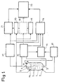
- transducers 4, 5, 6 and 7 On the enclosure and on either side thereof in the vertical direction and in a neighboring direction are arranged transducers 4, 5, 6 and 7 making it possible to emit and collect ultrasonic waves through the filling fluid the enclosure 1. Between the transducers 4 and 5, the straight distance over which the ultrasonic waves propagate is practically identical to the length over which the waves propagate between the transducers 6 and 7.
- the transducers 6 and 7 allow the emission and reception of an ultrasonic wave at low frequency, of the order of 1 KHz.
- the transducers 4 and 5 allow the emission and reception of ultrasonic waves at high frequency of the order of 1 M Hz.
- the transducer 4 also makes it possible to collect on return the ultrasonic waves emitted in the vertical direction, after reflection on the upper level 8 of the water containing the bubbles.
- Calculation units 10 and 11 make it possible to determine the propagation time in the fluid filling the enclosure, high frequency waves and low frequency waves respectively.
- a computer 12 allows the calculation of the difference between the propagation times of low frequency waves and high frequency waves.
- the speed of propagation of ultrasonic waves in a homogeneous medium is independent of the frequency of these waves.
- a pressure sensor 14 inside the container 1 makes it possible to determine the equilibrium pressure of the steam and of the water in this container. This pressure corresponds to a well-determined value of the temperature of the fluid in enclosure 1.
- the vapor contained in the container 1 is in its entirety in the form of a layer overlying the water under pressure not sprayed.
- calculation units 15 and 16 make it possible to determine the speed of the ultrasound in steam and in water at the pressure measured by the sensor 14.
- the length of the ultrasound path in the vapor which is simply linked to the vacuum rate in the enclosure can be very easily determined from the propagation time of the waves and the velocities of the ultrasound in the vapor and in the at the pressure considered.
- the overall vacuum rate is equal to the vacuum rate due to the vapor in the stratified phase obtained by means of the calculation unit 18.
- a second way of obtaining the vacuum rate is to collect by means of the transducer 4 the ultrasonic waves reflected by the surface 8 of the water, after a course representing twice the height h of the layer of vapor above water in enclosure 1.
- a calculation unit 20 makes it possible to determine the propagation time of the ultrasonic waves in the vapor, the length of the path of these ultrasonic waves being equal to 2 h.
- the calculation unit 21 makes it possible to determine from the propagation time of the waves in the steam supplied by the calculation unit 20 and from the speed of the ultrasound in the steam at the pressure considered supplied by the calculation unit 15, the vacuum rate due to the vapor in the stratified phase above the water. This value is equal to the accuracy of the measurement close to the value obtained using the calculation unit 18.
- FIG. 2 the variations of the speed of sound are shown in a stratified water-vapor mixture filling a horizontal cylindrical pipe as a function of the vacuum rate a and for different pressures of the fluid filling the pipe corresponding to well-determined temperatures of this fluid.
- a calculation unit having in memory the equations of the curves as represented in FIG. 2 and for a sufficient number of pressures to allow extrapolation leads to the immediate determination of the vacuum rate a from the time of propagation of the ultrasonic waves in the pipe containing water surmounted by steam.
- the vapor is at least partially in the form of bubbles distributed in non-vaporized water.
- the presence of a liquid-vapor interface 8 can be determined by capturing the reflected wave possibly on the surface 8, thanks to the transducer 4.
- the calculation unit 20 already described makes it possible to calculate the propagation time of the waves in the vapor, following a round trip between the transducer 4 and the level 8.
- Such curves can be stored in large quantities in a calculation unit 24 receiving as input data the propagation time of the high frequency waves determined by the calculation unit 10, the propagation time of the waves in the vapor, in coming from the calculation unit 20 and the pressure of the fluid filling the enclosure 1. From these input data and the relationships or graphs stored in memory, the calculation unit 24 makes it possible to determine the speed of the high waves frequency in water containing bubbles of vapor and the rate of vacuum due to the vapor in the form of bubbles.
- This vacuum rate is added to the vacuum rate due to the vapor in the stratified phase calculated by the unit 21, in a computer 25.
- the computer 25 can then give the value of the overall vacuum rate in the enclosure 1.
- the processing by the calculation unit 24 is triggered when a difference is detected at the level of the calculation unit 12 between the propagation times of the low and high frequency waves.
- a calculation unit is used for this purpose, having in memory the curves or relationships between the propagation speed of the waves and the frequency in a mixture of water and vapor bubbles, according to the pressure and according to the vacuum rate. Such curves are shown in FIG. 3.
- L designates the length of the wave path throughout the crossing of the container 1
- V being the speed of the ultrasonic waves in the vapor at the pressure considered
- Ci (BF) and C 1 ((HF) the speeds of the ultrasonic waves in the liquid containing the bubbles at the pressure considered, for the low frequency and high waves frequency, respectively.
- the input data to the calculation unit are the propagation times ⁇ t BF and ⁇ t HF, the pressure and the speed of propagation of the ultrasound in the vapor, which makes it possible to determine the value of the height h of the vapor layer and the vacuum rate due to the vapor bubbles in the water.
- the vacuum rate due to the stratified vapor and the overall vacuum rate is deduced by the calculation unit by adding this vacuum rate due to the stratified steam and the vacuum rate due to the steam bubbles in water.
- This apparatus comprises two pairs of transducers 32, 33 and 34, 35 arranged in a diagonally opposite manner on the pipe 30.
- the pair of transducers 32-33 allows the emission and the capture of an ultrasonic wave at a first frequency, while the pair of transducers 34-35 allows the emission and the capture of an ultrasonic wave at a second frequency.
- the propagation times of these ultrasonic waves in the fluid filling the pipe 30 are calculated by calculation units 36 and 37.
- a calculation unit 38 makes it possible to calculate the ratio between the difference in wave propagation times and the difference in frequency logarithms.
- a pressure sensor 40 is arranged inside the pipe 30 to supply a signal representative of the pressure of the fluid filling the pipe 30 to a calculation unit 42 also receiving from the calculation unit 38 a signal representative of the ratio of the differences in travel time unlike frequencies of ultrasonic waves.
- the calculation unit 42 a stored in memory, the relationships between ultrasonic wave speed and frequency, according to the different vacuum rates and according to the different pressures, determined by calibration and as shown, for example according to FIG. 3.
- the calculation unit 42 allows a comparison of the ratio with the slope of the curves giving the variation of the speed of sound as a function of frequency.
- the frequencies F1 and F2 are relatively close, so that the comparison of the slopes and the ratio is done in the vicinity of one of the frequencies or of an average frequency. This makes it possible to determine the void rate since, as can be seen in FIG. 3, the slopes of the curves vary greatly with the void rate.
- the measurement of the void rate can therefore be done very quickly using relatively close frequencies for the two ultrasonic waves.
- This simplified method of determining the vacuum rate is very useful in the first phases following a rupture on the primary circuit of a pressurized water reactor.
- the safety systems are designed in such a way that it is entirely unlikely that an accident could lead to vaporization with the formation of a stratified vapor layer.
- the device can make it possible to determine the proportion of gas in a liquid contained in an enclosure or a pipe.
- the invention is not limited to the embodiments which have been described.
- the enclosure contains a liquid having gas bubbles in suspension
- the frequencies of the ultrasonic waves and the paths of these inside the fluid it is possible to choose in any way the frequencies of the ultrasonic waves and the paths of these inside the fluid.
- the process according to the invention applies not only in the case of the determination of the vacuum rate in the primary circuit of a pressurized water nuclear reactor but also in the case of any pressurized liquid capable of vaporizing. and even in the case of any liquid which may contain a gas in a variable proportion.
Landscapes
- Physics & Mathematics (AREA)
- Biochemistry (AREA)
- General Physics & Mathematics (AREA)
- Life Sciences & Earth Sciences (AREA)
- Chemical & Material Sciences (AREA)
- Analytical Chemistry (AREA)
- Pathology (AREA)
- General Health & Medical Sciences (AREA)
- Health & Medical Sciences (AREA)
- Immunology (AREA)
- Acoustics & Sound (AREA)
- Investigating Or Analyzing Materials By The Use Of Ultrasonic Waves (AREA)
- Monitoring And Testing Of Nuclear Reactors (AREA)
- Measurement Of Mechanical Vibrations Or Ultrasonic Waves (AREA)
- Measurement Of Levels Of Liquids Or Fluent Solid Materials (AREA)
Applications Claiming Priority (2)
| Application Number | Priority Date | Filing Date | Title |
|---|---|---|---|
| FR8202750A FR2522153A1 (fr) | 1982-02-19 | 1982-02-19 | Procede de mesure par ultrasons du rapport du volume de gaz present dans une enceinte contenant un melange liquide-gaz au volume total de l'enceinte |
| FR8202750 | 1982-02-19 |
Publications (2)
| Publication Number | Publication Date |
|---|---|
| EP0087365A1 EP0087365A1 (fr) | 1983-08-31 |
| EP0087365B1 true EP0087365B1 (fr) | 1986-05-14 |
Family
ID=9271153
Family Applications (1)
| Application Number | Title | Priority Date | Filing Date |
|---|---|---|---|
| EP83400344A Expired EP0087365B1 (fr) | 1982-02-19 | 1983-02-18 | Procédé de mesure par ultrasons du rapport du volume de gaz présent dans une enceinte contenant un mélange liquide-gaz au volume total de l'enceinte |
Country Status (10)
| Country | Link |
|---|---|
| US (1) | US4491008A (enExample) |
| EP (1) | EP0087365B1 (enExample) |
| JP (1) | JPS58155356A (enExample) |
| KR (1) | KR840003842A (enExample) |
| CA (1) | CA1191935A (enExample) |
| DE (1) | DE3363474D1 (enExample) |
| ES (1) | ES8503436A1 (enExample) |
| FR (1) | FR2522153A1 (enExample) |
| YU (1) | YU29383A (enExample) |
| ZA (1) | ZA83498B (enExample) |
Families Citing this family (19)
| Publication number | Priority date | Publication date | Assignee | Title |
|---|---|---|---|---|
| FR2551906B1 (fr) * | 1983-09-13 | 1986-03-14 | Framatome Sa | Procede de controle des fuites du circuit primaire d'un reacteur nucleaire a eau sous pression |
| DE3438045C2 (de) * | 1983-11-04 | 1986-12-18 | Endress U. Hauser Gmbh U. Co, 7867 Maulburg | Anordnung zur Signalübertragung bei Ultraschall-Echolotgeräten |
| DE3421176A1 (de) * | 1984-06-07 | 1985-12-19 | Sartorius GmbH, 3400 Göttingen | Vorrichtung zum akustischen nachweis von gasblasen in fluessigkeiten wie blut oder infusionsloesungen |
| US4726221A (en) * | 1986-10-02 | 1988-02-23 | Syracuse University | Ultrasonic measurement of dispersed phase volumetric holdup in liquid/liquid dispersions |
| USH608H (en) | 1986-12-30 | 1989-03-07 | Shell Oil Company | Detecting multiple phase flow in a conduit |
| US5035140A (en) * | 1988-11-03 | 1991-07-30 | The Boeing Company | Self cleaning liquid level detector |
| FR2714471B1 (fr) * | 1993-12-28 | 1996-03-15 | Inst Francais Du Petrole | Dispositif et méthode de détection d'interfaces séparant plusieurs phases par ondes ultrasonores. |
| DE19648236A1 (de) * | 1996-11-22 | 1998-05-28 | Kathoefer Ets Gmbh | Verfahren und Vorrichtung zur Bestimmung von Stoffkennwerten von Flüssigkeiten |
| US6680994B2 (en) * | 1997-09-19 | 2004-01-20 | British Nuclear Fuels Plc | Monitoring the contents of a container by ultrasonic means |
| WO2006130499A2 (en) | 2005-05-27 | 2006-12-07 | Cidra Corporation | An apparatus and method for fiscal measuring of an aerated fluid |
| US7526966B2 (en) * | 2005-05-27 | 2009-05-05 | Expro Meters, Inc. | Apparatus and method for measuring a parameter of a multiphase flow |
| RU2292040C1 (ru) * | 2005-06-15 | 2007-01-20 | Открытое акционерное общество "Урало-Сибирские магистральные нефтепроводы имени Д.А. Черняева" | Способ градуировки средства для измерения объемной доли свободного газа |
| CA2637011C (en) * | 2006-01-11 | 2016-06-14 | Expro Meters, Inc. | An apparatus and method for measuring a parameter of a multiphase flow |
| RU2438102C2 (ru) * | 2009-02-10 | 2011-12-27 | Владимир Иванович Мельников | Ультразвуковой сигнализатор уровня жидкости в.и. мельникова |
| GB2472191A (en) * | 2009-07-24 | 2011-02-02 | Wayne Rudd | Method and apparatus for characterising a medium |
| EP3683575A1 (en) * | 2019-01-18 | 2020-07-22 | TE Connectivity Norge AS | System and method for detecting the presence of bubbles in aqueous solutions |
| EP3822613B1 (en) * | 2019-11-13 | 2023-09-06 | ABB Schweiz AG | Measurement system for determining liquid properties in a vessel |
| JP7072269B2 (ja) * | 2020-03-30 | 2022-05-20 | 学校法人福岡工業大学 | ボイド率計測装置およびボイド率計測方法 |
| KR102497237B1 (ko) * | 2020-10-08 | 2023-02-07 | 한국원자력연구원 | 기포 탐지장치 |
Family Cites Families (8)
| Publication number | Priority date | Publication date | Assignee | Title |
|---|---|---|---|---|
| US3100885A (en) * | 1961-08-14 | 1963-08-13 | Gulton Ind Inc | Ultrasonic liquid level gauge |
| US3359787A (en) * | 1964-12-24 | 1967-12-26 | Mobil Oil Corp | Method and apparatus for monitoring liquids |
| US3744301A (en) * | 1971-09-09 | 1973-07-10 | Atomic Energy Commission | Ultrasonic void fraction detector |
| FR2159576A6 (enExample) * | 1971-11-04 | 1973-06-22 | Realisa Ultrasoniques | |
| DE2217308A1 (de) * | 1972-04-11 | 1973-10-25 | Bosch Gmbh Robert | Verfahren und vorrichtung zur messung des anteils an freier, ungeloester luft in druckfluessigkeit |
| GB1482350A (en) * | 1973-09-17 | 1977-08-10 | Atomic Energy Authority Uk | Ultra sonic testing |
| US4135387A (en) * | 1977-08-10 | 1979-01-23 | Westinghouse Electric Corp. | Device for monitoring phase proportions of a single component fluid |
| FR2478314A1 (fr) * | 1980-03-12 | 1981-09-18 | Commissariat Energie Atomique | Procede et dispositif de mesure de la fraction volumique de l'une ou l'autre des phases d'un melange diphasique |
-
1982
- 1982-02-19 FR FR8202750A patent/FR2522153A1/fr active Granted
-
1983
- 1983-01-26 ZA ZA83498A patent/ZA83498B/xx unknown
- 1983-02-08 YU YU00293/83A patent/YU29383A/xx unknown
- 1983-02-08 ES ES519607A patent/ES8503436A1/es not_active Expired
- 1983-02-17 US US06/467,567 patent/US4491008A/en not_active Expired - Lifetime
- 1983-02-18 DE DE8383400344T patent/DE3363474D1/de not_active Expired
- 1983-02-18 KR KR1019830000669A patent/KR840003842A/ko not_active Withdrawn
- 1983-02-18 JP JP58026126A patent/JPS58155356A/ja active Pending
- 1983-02-18 CA CA000421915A patent/CA1191935A/fr not_active Expired
- 1983-02-18 EP EP83400344A patent/EP0087365B1/fr not_active Expired
Also Published As
| Publication number | Publication date |
|---|---|
| ES519607A0 (es) | 1985-02-16 |
| YU29383A (en) | 1986-02-28 |
| ZA83498B (en) | 1983-10-26 |
| FR2522153B1 (enExample) | 1984-04-06 |
| CA1191935A (fr) | 1985-08-13 |
| JPS58155356A (ja) | 1983-09-16 |
| ES8503436A1 (es) | 1985-02-16 |
| FR2522153A1 (fr) | 1983-08-26 |
| US4491008A (en) | 1985-01-01 |
| DE3363474D1 (en) | 1986-06-19 |
| EP0087365A1 (fr) | 1983-08-31 |
| KR840003842A (ko) | 1984-10-04 |
Similar Documents
| Publication | Publication Date | Title |
|---|---|---|
| EP0087365B1 (fr) | Procédé de mesure par ultrasons du rapport du volume de gaz présent dans une enceinte contenant un mélange liquide-gaz au volume total de l'enceinte | |
| EP0399876B1 (fr) | Procédé et dispositif pour mesurer des qualités d'un fluide polyphasique | |
| EP0661527B1 (fr) | Dispositif et méthode de détection d'interfaces séparant plusieurs phases par ondes ultrasonores | |
| EP0691536B1 (fr) | Débitmètre polyphasique | |
| EP2115451B1 (fr) | Procede de mesure de la pression et/ou de la masse molaire d'un gaz dans une enceinte, et ensemble de mesure correspondant | |
| FR2588086A1 (fr) | Procede et dispositif de detection par ultrasons de bulles de gaz dans un metal liquide | |
| FR2465225A1 (fr) | Procede de controle de defauts dans des produits tubulaires | |
| FR2833705A1 (fr) | Capteur detecteur d'interface | |
| FR2472177A1 (fr) | Mesureur de niveau pour liquide, notamment pour l'eau de refroidissement d'un reacteur | |
| US7942066B1 (en) | Non-intrusive two-phase flow measurement system | |
| EP1064533B1 (fr) | Dispositif et procede de mesure directe de l'energie calorifique contenue dans un gaz combustible | |
| FR2538155A1 (fr) | Procede et dispositif de detection d'elements combustibles defectueux utilisant l'absorption ultrasonore | |
| FR2940444A1 (fr) | Procede de caracterisation non destructif et sans contact d'une structure multi-couche sensiblement spherique et dispositif associe | |
| EP0348289B1 (fr) | Dispositif de détection et de mesure par échographie de particules sédimentant dans un liquide. | |
| EP0718616B1 (fr) | Méthode et dispositif de mesure en continu des variations de la saturation globale d'un échantillon en fluides non miscibles incompressibles | |
| EP0035936B1 (fr) | Procédé et dispositif pour contrôler le fonctionnement d'une colonne d'extraction liquide-liquide | |
| EP0571519B1 (fr) | Procede et dispositif pour la mesure et la surveillance du niveau d'un liquide, a partir d'un repere fixe, au moyen des ultrasons | |
| FR2522140A1 (fr) | Procede et dispositif pour la mesure du niveau du liquide dans des recipients | |
| EP4204773B1 (fr) | Procédé et système pour la détermination temporelle d'un niveau d'interface de phase d'un fluide polyphasique présent dans une conduite verticale | |
| EP0053068B1 (fr) | Dispositif de détection de phase gazeuse dans un réacteur nucléaire | |
| WO1994001747A1 (fr) | Dispositif indicateur du debit d'une fuite d'un circuit primaire de reacteur nucleaire | |
| FR2960061A1 (fr) | Procede de determination de taux de vide par spectrometrie de resonance acoustique non lineaire dans un milieu diphasique et application dans un reacteur nucleaire | |
| FR2657693A1 (fr) | Procede de detection par ultrasons de l'apparition d'une phase gazeuse dans une phase liquide contenue dans une enceinte | |
| FR2735228A1 (fr) | Procede et appareil de mesure permettant de detecter des interfaces | |
| RU2137119C1 (ru) | Устройство для определения растворенных в диэлектрических жидкостях водорода и влаги |
Legal Events
| Date | Code | Title | Description |
|---|---|---|---|
| PUAI | Public reference made under article 153(3) epc to a published international application that has entered the european phase |
Free format text: ORIGINAL CODE: 0009012 |
|
| AK | Designated contracting states |
Designated state(s): BE CH DE GB IT LI SE |
|
| 17P | Request for examination filed |
Effective date: 19830816 |
|
| GRAA | (expected) grant |
Free format text: ORIGINAL CODE: 0009210 |
|
| AK | Designated contracting states |
Kind code of ref document: B1 Designated state(s): BE CH DE GB IT LI SE |
|
| ITF | It: translation for a ep patent filed | ||
| REF | Corresponds to: |
Ref document number: 3363474 Country of ref document: DE Date of ref document: 19860619 |
|
| PLBE | No opposition filed within time limit |
Free format text: ORIGINAL CODE: 0009261 |
|
| STAA | Information on the status of an ep patent application or granted ep patent |
Free format text: STATUS: NO OPPOSITION FILED WITHIN TIME LIMIT |
|
| 26N | No opposition filed | ||
| ITTA | It: last paid annual fee | ||
| PGFP | Annual fee paid to national office [announced via postgrant information from national office to epo] |
Ref country code: CH Payment date: 19950116 Year of fee payment: 13 |
|
| PGFP | Annual fee paid to national office [announced via postgrant information from national office to epo] |
Ref country code: DE Payment date: 19950119 Year of fee payment: 13 |
|
| EAL | Se: european patent in force in sweden |
Ref document number: 83400344.4 |
|
| PGFP | Annual fee paid to national office [announced via postgrant information from national office to epo] |
Ref country code: GB Payment date: 19950210 Year of fee payment: 13 |
|
| PGFP | Annual fee paid to national office [announced via postgrant information from national office to epo] |
Ref country code: SE Payment date: 19950220 Year of fee payment: 13 |
|
| PGFP | Annual fee paid to national office [announced via postgrant information from national office to epo] |
Ref country code: BE Payment date: 19950222 Year of fee payment: 13 |
|
| PG25 | Lapsed in a contracting state [announced via postgrant information from national office to epo] |
Ref country code: GB Effective date: 19960218 |
|
| PG25 | Lapsed in a contracting state [announced via postgrant information from national office to epo] |
Ref country code: SE Effective date: 19960219 |
|
| PG25 | Lapsed in a contracting state [announced via postgrant information from national office to epo] |
Ref country code: LI Free format text: LAPSE BECAUSE OF NON-PAYMENT OF DUE FEES Effective date: 19960228 Ref country code: CH Free format text: LAPSE BECAUSE OF NON-PAYMENT OF DUE FEES Effective date: 19960228 Ref country code: BE Effective date: 19960228 |
|
| BERE | Be: lapsed |
Owner name: FRAMATOME ET CIE. Effective date: 19960228 |
|
| GBPC | Gb: european patent ceased through non-payment of renewal fee |
Effective date: 19960218 |
|
| REG | Reference to a national code |
Ref country code: CH Ref legal event code: PL |
|
| PG25 | Lapsed in a contracting state [announced via postgrant information from national office to epo] |
Ref country code: DE Effective date: 19961101 |