EP1982169B1 - Apparatus and method for measuring parameters of a multiphase fluid flow - Google Patents
Apparatus and method for measuring parameters of a multiphase fluid flow Download PDFInfo
- Publication number
- EP1982169B1 EP1982169B1 EP07762897A EP07762897A EP1982169B1 EP 1982169 B1 EP1982169 B1 EP 1982169B1 EP 07762897 A EP07762897 A EP 07762897A EP 07762897 A EP07762897 A EP 07762897A EP 1982169 B1 EP1982169 B1 EP 1982169B1
- Authority
- EP
- European Patent Office
- Prior art keywords
- flow
- pipe
- sensing device
- sound
- fluid
- Prior art date
- Legal status (The legal status is an assumption and is not a legal conclusion. Google has not performed a legal analysis and makes no representation as to the accuracy of the status listed.)
- Active
Links
- 239000012530 fluid Substances 0.000 title claims description 90
- 238000000034 method Methods 0.000 title claims description 66
- 239000007789 gas Substances 0.000 claims description 68
- 238000005259 measurement Methods 0.000 claims description 60
- 239000007788 liquid Substances 0.000 claims description 51
- 230000008569 process Effects 0.000 claims description 41
- 238000012545 processing Methods 0.000 claims description 33
- 230000001902 propagating effect Effects 0.000 claims description 33
- XLYOFNOQVPJJNP-UHFFFAOYSA-N water Substances O XLYOFNOQVPJJNP-UHFFFAOYSA-N 0.000 claims description 22
- 238000009434 installation Methods 0.000 claims description 2
- 230000007704 transition Effects 0.000 claims description 2
- 239000000203 mixture Substances 0.000 description 54
- 239000012071 phase Substances 0.000 description 43
- 230000006870 function Effects 0.000 description 20
- 239000003921 oil Substances 0.000 description 15
- 238000010586 diagram Methods 0.000 description 14
- 239000011800 void material Substances 0.000 description 11
- 230000000694 effects Effects 0.000 description 10
- 230000002123 temporal effect Effects 0.000 description 10
- 239000000463 material Substances 0.000 description 8
- 230000008901 benefit Effects 0.000 description 6
- 230000003595 spectral effect Effects 0.000 description 5
- 230000003044 adaptive effect Effects 0.000 description 4
- 239000007791 liquid phase Substances 0.000 description 4
- 238000004519 manufacturing process Methods 0.000 description 4
- 239000002245 particle Substances 0.000 description 4
- 239000002033 PVDF binder Substances 0.000 description 3
- 230000001427 coherent effect Effects 0.000 description 3
- 238000007906 compression Methods 0.000 description 3
- 230000006835 compression Effects 0.000 description 3
- 230000000875 corresponding effect Effects 0.000 description 3
- 239000010779 crude oil Substances 0.000 description 3
- 239000000835 fiber Substances 0.000 description 3
- 230000003287 optical effect Effects 0.000 description 3
- 229920002981 polyvinylidene fluoride Polymers 0.000 description 3
- 230000004044 response Effects 0.000 description 3
- 238000005070 sampling Methods 0.000 description 3
- 230000035945 sensitivity Effects 0.000 description 3
- 238000000926 separation method Methods 0.000 description 3
- 239000000126 substance Substances 0.000 description 3
- 238000005273 aeration Methods 0.000 description 2
- 230000005540 biological transmission Effects 0.000 description 2
- 238000009530 blood pressure measurement Methods 0.000 description 2
- 238000012937 correction Methods 0.000 description 2
- 238000000354 decomposition reaction Methods 0.000 description 2
- 230000001934 delay Effects 0.000 description 2
- 238000001739 density measurement Methods 0.000 description 2
- 230000001419 dependent effect Effects 0.000 description 2
- 239000006185 dispersion Substances 0.000 description 2
- 238000000605 extraction Methods 0.000 description 2
- 238000011068 loading method Methods 0.000 description 2
- 238000005457 optimization Methods 0.000 description 2
- 239000000123 paper Substances 0.000 description 2
- 239000003208 petroleum Substances 0.000 description 2
- 239000002002 slurry Substances 0.000 description 2
- 238000013517 stratification Methods 0.000 description 2
- 238000012935 Averaging Methods 0.000 description 1
- 238000012369 In process control Methods 0.000 description 1
- 230000001133 acceleration Effects 0.000 description 1
- 238000007792 addition Methods 0.000 description 1
- 238000013459 approach Methods 0.000 description 1
- 238000003491 array Methods 0.000 description 1
- 230000003190 augmentative effect Effects 0.000 description 1
- 230000009286 beneficial effect Effects 0.000 description 1
- 230000008859 change Effects 0.000 description 1
- 238000012512 characterization method Methods 0.000 description 1
- 230000001276 controlling effect Effects 0.000 description 1
- 229920001577 copolymer Polymers 0.000 description 1
- 230000002596 correlated effect Effects 0.000 description 1
- 238000005260 corrosion Methods 0.000 description 1
- 230000007797 corrosion Effects 0.000 description 1
- 238000006073 displacement reaction Methods 0.000 description 1
- 238000005516 engineering process Methods 0.000 description 1
- 230000005284 excitation Effects 0.000 description 1
- 238000001914 filtration Methods 0.000 description 1
- 238000010304 firing Methods 0.000 description 1
- 229920002313 fluoropolymer Polymers 0.000 description 1
- 239000004811 fluoropolymer Substances 0.000 description 1
- 239000011888 foil Substances 0.000 description 1
- 238000009472 formulation Methods 0.000 description 1
- 229930195733 hydrocarbon Natural products 0.000 description 1
- 150000002430 hydrocarbons Chemical class 0.000 description 1
- 230000006872 improvement Effects 0.000 description 1
- 238000010965 in-process control Methods 0.000 description 1
- 238000011065 in-situ storage Methods 0.000 description 1
- 229910052500 inorganic mineral Inorganic materials 0.000 description 1
- 238000012423 maintenance Methods 0.000 description 1
- 238000000691 measurement method Methods 0.000 description 1
- 238000004377 microelectronic Methods 0.000 description 1
- 239000011707 mineral Substances 0.000 description 1
- 238000005065 mining Methods 0.000 description 1
- 238000002156 mixing Methods 0.000 description 1
- 238000012986 modification Methods 0.000 description 1
- 230000004048 modification Effects 0.000 description 1
- 238000012544 monitoring process Methods 0.000 description 1
- 239000013307 optical fiber Substances 0.000 description 1
- 229920000642 polymer Polymers 0.000 description 1
- -1 pulp Substances 0.000 description 1
- 239000010453 quartz Substances 0.000 description 1
- VYPSYNLAJGMNEJ-UHFFFAOYSA-N silicon dioxide Inorganic materials O=[Si]=O VYPSYNLAJGMNEJ-UHFFFAOYSA-N 0.000 description 1
- 239000008247 solid mixture Substances 0.000 description 1
- 239000007790 solid phase Substances 0.000 description 1
- 238000010183 spectrum analysis Methods 0.000 description 1
- 239000000758 substrate Substances 0.000 description 1
- 238000012360 testing method Methods 0.000 description 1
- 238000012546 transfer Methods 0.000 description 1
- 239000002023 wood Substances 0.000 description 1
Images


Classifications
-
- G—PHYSICS
- G01—MEASURING; TESTING
- G01F—MEASURING VOLUME, VOLUME FLOW, MASS FLOW OR LIQUID LEVEL; METERING BY VOLUME
- G01F1/00—Measuring the volume flow or mass flow of fluid or fluent solid material wherein the fluid passes through a meter in a continuous flow
- G01F1/66—Measuring the volume flow or mass flow of fluid or fluent solid material wherein the fluid passes through a meter in a continuous flow by measuring frequency, phase shift or propagation time of electromagnetic or other waves, e.g. using ultrasonic flowmeters
- G01F1/667—Arrangements of transducers for ultrasonic flowmeters; Circuits for operating ultrasonic flowmeters
-
- G—PHYSICS
- G01—MEASURING; TESTING
- G01F—MEASURING VOLUME, VOLUME FLOW, MASS FLOW OR LIQUID LEVEL; METERING BY VOLUME
- G01F1/00—Measuring the volume flow or mass flow of fluid or fluent solid material wherein the fluid passes through a meter in a continuous flow
- G01F1/704—Measuring the volume flow or mass flow of fluid or fluent solid material wherein the fluid passes through a meter in a continuous flow using marked regions or existing inhomogeneities within the fluid stream, e.g. statistically occurring variations in a fluid parameter
- G01F1/708—Measuring the time taken to traverse a fixed distance
- G01F1/712—Measuring the time taken to traverse a fixed distance using auto-correlation or cross-correlation detection means
-
- G—PHYSICS
- G01—MEASURING; TESTING
- G01F—MEASURING VOLUME, VOLUME FLOW, MASS FLOW OR LIQUID LEVEL; METERING BY VOLUME
- G01F1/00—Measuring the volume flow or mass flow of fluid or fluent solid material wherein the fluid passes through a meter in a continuous flow
- G01F1/74—Devices for measuring flow of a fluid or flow of a fluent solid material in suspension in another fluid
-
- G—PHYSICS
- G01—MEASURING; TESTING
- G01N—INVESTIGATING OR ANALYSING MATERIALS BY DETERMINING THEIR CHEMICAL OR PHYSICAL PROPERTIES
- G01N29/00—Investigating or analysing materials by the use of ultrasonic, sonic or infrasonic waves; Visualisation of the interior of objects by transmitting ultrasonic or sonic waves through the object
- G01N29/02—Analysing fluids
- G01N29/024—Analysing fluids by measuring propagation velocity or propagation time of acoustic waves
-
- G—PHYSICS
- G01—MEASURING; TESTING
- G01N—INVESTIGATING OR ANALYSING MATERIALS BY DETERMINING THEIR CHEMICAL OR PHYSICAL PROPERTIES
- G01N29/00—Investigating or analysing materials by the use of ultrasonic, sonic or infrasonic waves; Visualisation of the interior of objects by transmitting ultrasonic or sonic waves through the object
- G01N29/22—Details, e.g. general constructional or apparatus details
- G01N29/222—Constructional or flow details for analysing fluids
-
- G—PHYSICS
- G01—MEASURING; TESTING
- G01N—INVESTIGATING OR ANALYSING MATERIALS BY DETERMINING THEIR CHEMICAL OR PHYSICAL PROPERTIES
- G01N29/00—Investigating or analysing materials by the use of ultrasonic, sonic or infrasonic waves; Visualisation of the interior of objects by transmitting ultrasonic or sonic waves through the object
- G01N29/34—Generating the ultrasonic, sonic or infrasonic waves, e.g. electronic circuits specially adapted therefor
- G01N29/348—Generating the ultrasonic, sonic or infrasonic waves, e.g. electronic circuits specially adapted therefor with frequency characteristics, e.g. single frequency signals, chirp signals
-
- G—PHYSICS
- G01—MEASURING; TESTING
- G01N—INVESTIGATING OR ANALYSING MATERIALS BY DETERMINING THEIR CHEMICAL OR PHYSICAL PROPERTIES
- G01N29/00—Investigating or analysing materials by the use of ultrasonic, sonic or infrasonic waves; Visualisation of the interior of objects by transmitting ultrasonic or sonic waves through the object
- G01N29/36—Detecting the response signal, e.g. electronic circuits specially adapted therefor
- G01N29/42—Detecting the response signal, e.g. electronic circuits specially adapted therefor by frequency filtering or by tuning to resonant frequency
-
- G—PHYSICS
- G01—MEASURING; TESTING
- G01N—INVESTIGATING OR ANALYSING MATERIALS BY DETERMINING THEIR CHEMICAL OR PHYSICAL PROPERTIES
- G01N33/00—Investigating or analysing materials by specific methods not covered by groups G01N1/00 - G01N31/00
- G01N33/26—Oils; viscous liquids; paints; inks
- G01N33/28—Oils, i.e. hydrocarbon liquids
-
- G—PHYSICS
- G01—MEASURING; TESTING
- G01N—INVESTIGATING OR ANALYSING MATERIALS BY DETERMINING THEIR CHEMICAL OR PHYSICAL PROPERTIES
- G01N9/00—Investigating density or specific gravity of materials; Analysing materials by determining density or specific gravity
- G01N9/002—Investigating density or specific gravity of materials; Analysing materials by determining density or specific gravity using variation of the resonant frequency of an element vibrating in contact with the material submitted to analysis
-
- G—PHYSICS
- G01—MEASURING; TESTING
- G01N—INVESTIGATING OR ANALYSING MATERIALS BY DETERMINING THEIR CHEMICAL OR PHYSICAL PROPERTIES
- G01N9/00—Investigating density or specific gravity of materials; Analysing materials by determining density or specific gravity
- G01N9/24—Investigating density or specific gravity of materials; Analysing materials by determining density or specific gravity by observing the transmission of wave or particle radiation through the material
-
- G—PHYSICS
- G01—MEASURING; TESTING
- G01N—INVESTIGATING OR ANALYSING MATERIALS BY DETERMINING THEIR CHEMICAL OR PHYSICAL PROPERTIES
- G01N2291/00—Indexing codes associated with group G01N29/00
- G01N2291/02—Indexing codes associated with the analysed material
- G01N2291/024—Mixtures
- G01N2291/02416—Solids in liquids
-
- G—PHYSICS
- G01—MEASURING; TESTING
- G01N—INVESTIGATING OR ANALYSING MATERIALS BY DETERMINING THEIR CHEMICAL OR PHYSICAL PROPERTIES
- G01N2291/00—Indexing codes associated with group G01N29/00
- G01N2291/02—Indexing codes associated with the analysed material
- G01N2291/024—Mixtures
- G01N2291/02433—Gases in liquids, e.g. bubbles, foams
-
- G—PHYSICS
- G01—MEASURING; TESTING
- G01N—INVESTIGATING OR ANALYSING MATERIALS BY DETERMINING THEIR CHEMICAL OR PHYSICAL PROPERTIES
- G01N2291/00—Indexing codes associated with group G01N29/00
- G01N2291/02—Indexing codes associated with the analysed material
- G01N2291/028—Material parameters
- G01N2291/02818—Density, viscosity
-
- G—PHYSICS
- G01—MEASURING; TESTING
- G01N—INVESTIGATING OR ANALYSING MATERIALS BY DETERMINING THEIR CHEMICAL OR PHYSICAL PROPERTIES
- G01N2291/00—Indexing codes associated with group G01N29/00
- G01N2291/02—Indexing codes associated with the analysed material
- G01N2291/028—Material parameters
- G01N2291/02827—Elastic parameters, strength or force
-
- G—PHYSICS
- G01—MEASURING; TESTING
- G01N—INVESTIGATING OR ANALYSING MATERIALS BY DETERMINING THEIR CHEMICAL OR PHYSICAL PROPERTIES
- G01N2291/00—Indexing codes associated with group G01N29/00
- G01N2291/02—Indexing codes associated with the analysed material
- G01N2291/028—Material parameters
- G01N2291/02836—Flow rate, liquid level
-
- G—PHYSICS
- G01—MEASURING; TESTING
- G01N—INVESTIGATING OR ANALYSING MATERIALS BY DETERMINING THEIR CHEMICAL OR PHYSICAL PROPERTIES
- G01N2291/00—Indexing codes associated with group G01N29/00
- G01N2291/02—Indexing codes associated with the analysed material
- G01N2291/028—Material parameters
- G01N2291/02872—Pressure
-
- G—PHYSICS
- G01—MEASURING; TESTING
- G01N—INVESTIGATING OR ANALYSING MATERIALS BY DETERMINING THEIR CHEMICAL OR PHYSICAL PROPERTIES
- G01N2291/00—Indexing codes associated with group G01N29/00
- G01N2291/10—Number of transducers
- G01N2291/106—Number of transducers one or more transducer arrays
Description
- This application is a continuation in part of
US Patent Application No. 11/442,954, filed May 30, 2006 U.S. Provisional Application No. 60/685,532 U.S. Provisional Application No. 60/736,684 U.S. Provisional Patent Application No. 60/758,242 - This invention relates to an apparatus for measuring a parameter of a process flow passing within a pipe, and more particularly to a flow measurement apparatus having ultrasonic sensors and an array of strain-based sensors and for processing data signals therefrom to provide an output indicative of the speed of sound propagating through the process flow and/or a flow parameter of the process flow passing through a pipe.
- In industrial applications that involve flowing fluids, such as slurries, liquids, chemical, paper, pulp, petroleum, gas, pharmaceutical, food, mining, minerals and vapors and gasses in refinery, it is sometimes beneficial to know certain characteristics of the flowing fluids. For example, in the petroleum industry in which billions of dollars of crude oil are fiscally measured each day on its way from the well heads to the refineries, the volumetric flow rate is a critical measurement in process control and optimization. Unfortunately however, large amounts of hydrocarbons tend to be present in crude oil and as such, during transport between the well heads and the refineries the crude oil has a propensity to 'out gas' during transport resulting in small, unknown levels of entrained gases being present at the fiscal measurement locations. This is undesirable for at least two (2) reasons.
- First, because the effect of the entrained gases on most known liquid volumetric technologies results in an over reporting of the liquid component flow rate by an amount equal to the volume of the entrained gases, the measured volumetric flow rate is typically inaccurate. In fact, standards have been imposed for volumetric flow. Unfortunately, however, while most standards for fiscal volumetric flow of liquids require that the liquid be completely devoid of gases, a problem arises when it becomes impractical to ensure that the liquid stream in question is indeed completely devoid of free gases. This is because although the gas volume fraction (GVF) level is typically less than 1%, it is often the primary source of error in the fiscal measurement. Second, because the complete separation of the gas and liquid phases cannot be ensured, the liquid volume determination is also typically inaccurate resulting in inaccurate watercut values. Thus, it is reasonable to expect that if more characteristics are known about the flowing fluid, there will be a better chance of effectively measuring, controlling, and optimizing the processing of the flowing fluid.
- Accuracy of oil production measurement is limited to three constraints. One constraint involves the inability to ensure the complete separation of gas and liquid flow. This constraint results in an inaccurate liquid volume determination, inaccurate gas volume determination and an inaccurate watercut determination. The second constraint involves the relatively low number of flow measurements available due to maintenance requirements, installation requirements and pressure drop in the point with any increase in measurement points. The third constraint involves the very low number of watercut measurement points, which is due to the reliability of the watercut measurement devices and the calibration requirements of the meters.
- In
US 2004/0168522 A1 there is disclosed an apparatus that measures the speed of sound and/or vortical disturbances propagating in a single phase fluid flow and/or multiphase mixture to determine parameters, such as mixture quality, particle size, vapour/mass ratio, liquid/vapour ratio, mass flow rate, enthalpy and volumetric flow rate of the flow in a pipe, by measuring acoustic and/or dynamic pressures. - In
US 4,491,008 there is disclosed a method of ultrasonic measurement of the ratio of the volume of gas present in an enclosure containing a liquid-gas mixture to the total volume of the enclosure. Particularly, an enclosure contains water and steam, where a portion of the steam is in the form of bubbles distributed within the water. Transducers transmit and receive high-frequency ultrasonic waves through the water and further transducers transmit and receive low-frequency ultrasonic waves through the water. A pressure detector determines the equilibrium pressure of the steam and the bubbly water inside the tank. - In
WO 01/69040 A1 - In
US 5,083,452 A there is disclosed a method for recording multi-phase flows through a transport system in which acoustic energy signals are sensed by one of a plurality of acoustic sensors. - In
US 2005/193832 A , a flowmeter includes a vibratable flowtube and a driver connected to the flowtube that is operable to impart motion to the flowtube. A sensor is connected to the flowtube and is operable to sense the motion of the flowtube and generate a sensor signal. A controller is connected to receive the sensor signal. The controller is operable to determine an individual flow rate of each phase within a multi-phase flow through the flowtube. - Thus, it would be advantageous, particularly in the oil and production field, to have a reliable, non-intrusive, clamp-on apparatus capable of measuring the parameters of an aerated multiphase fluid flow, such as the volumetric flow rate liquid of the process flow, the gas volume (or void) fraction of the flow, the watercut of the flow, and the volumetric flow rate of each of the phases of the flow. The present invention provides such an apparatus.
- An apparatus for determining a characteristic of an aerated fluid flowing within a pipe, according to
claim 1. - The foregoing and other objects, features and advantages of the present invention will become more apparent in light of the following detailed description of exemplary embodiments thereof.
- The foregoing and other features and advantages of the present invention will be more fully understood from the following detailed description of illustrative embodiments, taken in conjunction with the accompanying drawings in which like elements are numbered alike:
-
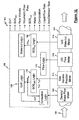
Figure 1 is a block diagram of a flow measurement apparatus having an array of strain-based sensors and an array of ultrasonic sensors for measuring parameters of a multiphase flow in accordance with the present invention. -
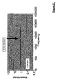
Figure 2 is a plot of the measured speed of sound normalized to the speed of sound of the liquid over a frequency range in accordance with the present invention. -
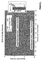
Figure 3 is a plot of the measured speed of sound normalized to the speed of sound of the liquid as a function of gas volume fraction in accordance with the present invention. -
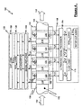
Figure 4 is a schematic diagram of a flow measurement apparatus ofFigure 1 having an array of strain-based sensors and an array of ultrasonic sensors for measuring parameters of a multiphase flow. -
Figure 5 is a cross-sectional view of a pipe having a turbulent fluid flow or mixture flowing therein, the flow having coherent structures therein, namely acoustic waves and vortical disturbances, in accordance with the present invention. -
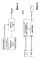
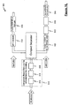
Figure 6 is a block diagram of the GVF Logic in accordance with the present invention. -
Figure 7 is a block diagram of the GVF Logic in accordance with the present invention. -
Figure 8 is a schematic diagram of a speed of sound (SOS) logic of an array processor of a flow measuring apparatus in accordance with the present invention. -
Figure 9 is a kω plot of data processed from an apparatus embodying the present invention that illustrates the slopes of a pair of acoustic ridges, in accordance with the present invention. -
Figure 10 is a plot of mixture sound speed as a function of gas volume fraction over a range of process pressures, in accordance with the present invention. -
Figure 11 is a schematic diagram of a flow logic of an array processor of a flow measuring apparatus in accordance with the present invention. -
Figure 12 a kω plot of data processed from an apparatus embodying the present invention that illustrates the slope of a convective ridge, and a plot of the optimization function of the convective ridge, in accordance with the present invention. -
Figure 13 is a plot of the speed of sound of the liquid as a function of the volume fraction of the water in the mutiphase flow in accordance with the present invention. -
Figure 14 is a block diagram of another embodiment of a flow measurement apparatus having an array of strain-based sensors and ultrasonic sensors for measuring parameters of a multiphase flow in accordance with the present invention. -
Figure 15 is a schematic diagram of a flow measurement apparatus ofFigure 14 having an array of strain-based sensors and an array of ultrasonic sensors for measuring parameters of a multiphase flow. -
Figure 16 is a schematic diagram of a flow measurement apparatus similar to that shown inFigure 1 which includes a density and/or mass flow meter such as a coriolis meter. -
Figure 17 is a clamp-on multi-phase (e.g. three phase) flow measurement apparatus comprising flow meter similar to that shown inFigure 15 having an array of strain-based sensors, a clamp-on density meter such as a nuclear densitometer, and at least one ultrasonic sensor to provide a watercut measurement, in accordance with the present invention. -
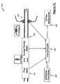
Figure 18 is schematic diagram of a system for monitoring and measuring flow parameters of a fluid separator, wherein the three phase measurement device ofFigure 17 is provided on the input pipe of the separator, the flow measurement device ofFigure 16 is provided on the liquid leg of the separator, and the wet gas flow measurement device is provided on the gas leg of the separator. -
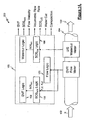
Figure 1 illustrates a block diagram of aflow measurement device 100 for measuring a parameter of amultiphase flow 102 passing through apipe 104. The multiphase flow ormixture 102 includes any mixture having any combination of a gas, liquid, or solid phase and while the present invention is particularly useful in measuring multiphase flows, it should be appreciated that theapparatus 100 can also measure a parameter of a single phase flow. As discussed hereinbefore, the apparatus embodying the present invention is useful in measuring a multiphase flow comprising oil, water and gas. The description of the present invention will therefore assume that the mixture is a combination of oil, water, and oil, however, the invention contemplates that any single or multiphase flow can be measured. - As shown in
Figure 1 , theapparatus 100 functions as a gas volume fraction (or void fraction) meter, an ultrasonic flow meter, and an ultrasonic watercut meter. The gas volume fraction (GVF) meter provides an output indicative of the gas volume fraction or void fraction of themixture 102 by measuring the speed of sound propagating at low frequencies axially through theflow 102 in thepipe 104. The ultrasonic flow meter provides a plurality of high frequency acoustic signals through theflow 102 to provide output signals indicative of pressure disturbances (e.g., vortical disturbances) propagating with theflow 102 past the ultrasonic sensors, which will be described in greater detail hereinafter. The ultrasonic watercut meter measures the speed of sound of a high frequency signal propagating through theflow 102 to provide an output signal indicative of the speed of sound of the liquid, which is indicative of the watercut of themixture 102, wherein watercut is the phase fraction or percentage of the water in theflow 102. - It should be appreciated that the combination of the GVF meter, flow meter and watercut meter provides sufficient information to fully characterize the
multiphase fluid 102 flowing through thepipe 104. Specifically, theapparatus 100 is capable of measuring at least the flow velocity, the volumetric flow rate, the flow composition (e.g., phase fraction), the watercut, the volumetric flow rate of a phase of the mixture, the gas volume (void) fraction of the flow, the speed of sound of the mixture, and the speed of sound of the liquid. One can appreciate that these measured parameters are particularly important in oil production applications. - One important aspect of the present invention involves the recognition that a frequency dependence of the speed of sound propagating through the
fluid flow 102 exists for bubbly fluids, wherein the bubble resonance determines the transition frequency.Figure 2 illustrates the frequency dependence of the speed of sound in bubbly fluids. As shown, at lower frequencies below the bubble resonant frequency (approximately 100 Hz to 1000 Hz), the speed of sound propagating through the fluid 102 is dramatically influenced by entrained gases. Conversely, at higher frequencies above the bubble resonant frequency (approximately 1 MHz and greater), entrained gas in thefluid flow 102 has no significant impact on the speed of sound propagating through the liquid. Recognizing this phenomenon, theapparatus 100 embodying the present invention provides a meter, such as a GVF meter, to measure the speed of sound at low frequencies below the bubble resonant frequency, and another meter, such as an ultrasonic watercut meter, to measure the speed of sound at high frequencies above the bubble resonant frequency. - As will be described in greater detail hereinafter, the measured speed of sound at the lower frequency (e.g., sub-resonant frequencies) is indicative of the speed of sound of the
mixture 102, while the measured speed of sound at the higher frequencies (e.g., super-resonant frequencies) is indicative of the speed of sound of the liquid. Knowing the speed of sound of themixture 102 enables the gas volume (and void) fraction of the flow 102 (or mixture) to be determined. Further, knowing the speed of sound of the liquid enables the watercut to be determined. This processing will be described in greater detail hereinafter. - Tests were performed using a vertical pipe filled with a fluid, wherein bubbles were injected into the fluid at the bottom of the pipe. Using an ultrasonic sensor and a GVF meter, the speed of sound at super-resonant frequencies and sub-resonant frequencies, respectively, were measured. Referring to
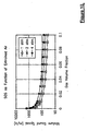
Figure 3 , the data obtained illustrates the phenomenon described hereinbefore that the measured speed of sound of the liquid (e.g., super-resonant SOS) is not affected by the entrained gas, while the measured speed of sound of the mixture 102 (e.g., sub-resonant SOS) is affected by the entrained gas. Additionally, the data inFigure 3 , which represents the illustrates the effects of the speed of sound of bubble mixtures or flows 102. Specifically, the measured speed of sound normalized by the liquid speed of sound is plotted as a function of the reference gas volume fraction. - The line A in
Figure 3 shows the normalized measured super-resonant speed of sound as a function of the referenced GVF. As discussed hereinbefore, the measured speed of sound at higher frequencies (super-resonant) is not affected by entrained gas and is indicative of the speed of sound of the liquid regardless of the amount of entrained gas. - The line B in
Figure 3 shows the normalized measured sub-resonant speed of sound as a function of the referenced GVF. As discussed hereinbefore, the measured sound speed at lower frequencies (sub-resonant) is affected by entrained gas by a known or determinable relationship, thus enabling the determination of the gas volume (or void) fraction of the multiphase flow ormixture 102. - The line C in
Figure 3 shows the theoretical normalized sub-resonant speed of sound of themixture 102 as a function of the referenced GVF in accordance with the Woods equation.. As can be seen, the measured sub-resonant speed of sound correlates with the theoretical determination of the sub-resonant speed of sound. - Referring to
Figure 4 a schematic diagram of theflow measurement apparatus 100 ofFigure 1 is illustrated, wherein theflow measurement apparatus 100 includes a sensing device (sensor head) 106 mounted to apipe 104 and a processing unit or array processor (transmitter) 108. In accordance with the present invention, theapparatus 100 can determine the speed at which sound (i.e.,acoustic wave 110 inFigure 5 ) propagates through thefluid flow 102 within thepipe 104 to measure particular characteristics of the single or multi-phase fluids. To simplify the explanation of the present invention, theflow 102 propagating through thepipe 104 will be referred to as a process flow with the understanding that the fluid orprocess flow 102 may be a single phase or multi-phase flow, as described hereinbefore. - The
sensing device 106 comprises an array of strain-based sensors or pressure sensors 112-118 for measuring the unsteady pressures produced by acoustic pressure disturbances (e.g., acoustic waves 110) within thepipe 104 to determine the speed of sound propagating through theflow 102. Thesensing device 106 further includes an array of ultrasonic sensors 120-126, each of which have atransmitter 160 and areceiver 162 to also measure a parameter of theflow 102. Although the pressure sensors 112-118 and ultrasonic sensors 120-126 are shown interlaced, it should be appreciated that each respective sensor array may be partially interlaced or not interlaced at all without departing from the present invention. It is also contemplated that the GVF meter and the ultrasonic flow meter may be two distinct units disposed adjacent to each other on thepipe 104. - The pressure signals P1(t) - PN(t) generated by the pressure sensors 112-118 and the ultrasonic signals S1(t) - SN(t) generated by the ultrasonic sensors 120-126 are provided to the
processing unit 108, which digitizes the signals and computes the appropriate flow parameter(s). A cable electronically connects thesensing device 106 to theprocessing unit 108. The analog pressure sensor signals P1(t) - PN(t) are typically 4-20 mA current loop signals. - The array of pressure sensors 112-118 comprises an array of at least two
pressure sensors outer surface 132 of thepipe 104, having aprocess flow 102 propagating therein. The pressure sensors 112-118 may be clamped onto or generally removably mounted to thepipe 104 by any releasable fastener, such as bolts, screws and clamps. Alternatively, the sensors 112-118 may be permanently attached to or integral (e.g., embedded) with thepipe 104. It should be appreciated that the array of sensors 112-118 of thesensing device 106 may include any number of pressure sensors 18-21 greater than two sensors, such as three, four, eight, sixteen or N number of sensors between two and twenty-four sensors. Generally, the accuracy of the measurement improves as the number of sensors in the array increases, wherein the degree of accuracy provided by the greater number of sensors is typically offset by the increase in complexity and time for computing the desired output parameter of theflow 102. Therefore, the number of sensors used is dependent at least in part on the degree of accuracy desired and the desire update rate of the output parameter provided by theapparatus 100. The pressure sensors 112-118 measure the unsteady pressures produced by acoustic waves propagating through theflow 102 within thepipe 104, which are indicative of the SOS propagating through thefluid flow 102 in thepipe 104. The output signals (P1(t)- PN(t)) of the pressure sensors 112-118 are provided to a signal amplifier 134 that amplifies the signals generated by the pressure sensors 112-118. Theprocessing unit 108 processes the pressure measurement data P1(t)-PN(t) and determines the desired parameters and characteristics of theflow 102, as described hereinbefore. - The
apparatus 100 also contemplates providing one or moreacoustic sources 136 to enable the measurement of the speed of sound propagating through theflow 102 for instances of acoustically quiet flow. Theacoustic source 136 may be a device that taps or vibrates on the wall of thepipe 104, for example. Theacoustic sources 136 may be disposed at the input end or the output end of the array of sensors 112-118, or at both ends as shown. One should appreciate that in most instances theacoustic sources 136 are not necessary and theapparatus 100 passively detects the acoustic ridge provided in theflow 102, as will be described in greater detail hereinafter. The passive noise includes noise generated by pumps, valves, motors, and the turbulent mixture itself. - Generally, the
processing unit 108 measures unsteady pressures created by acoustical disturbances propagating through theflow 102 to determine the speed of sound (SOS) propagating through theflow 102. Knowing the pressure and/or temperature of theflow 102 and the speed of sound of the acoustic disturbances or waves, as shown inFigure 6 and Figure 7 , theprocessing unit 108 can determine the volumetric flow of the fluid, the consistency or composition of the fluid, the Mach number of the fluid, the average size of particles flowing through the fluid, the air/mass ratio of the fluid, and/or the percentage of entrained air within themixture 102, such as that described inU.S. Patent Application No. 10/349,716 (CiDRA Docket No. CC-0579), filed January 23, 2003,U.S. Patent Application No. 10/376,427 (CiDRA Docket No. CC-0596), filed February 26, 2003,U.S. Patent Application No. 10/762,410 - As shown in
Figure 4 , anapparatus 100 embodying the present invention has an array of at least two strain-based or pressure sensors 112-114, located at two locations x1, x2 axially along thepipe 104 for sensing respective stochastic signals propagating between the sensors 112-114 within thepipe 104 at their respective locations. Each sensor 112-114 provides a signal indicating an unsteady pressure at the location of each sensor, at each instant in a series of sampling instants. One should appreciate that the sensor array may include more than two pressure sensors as depicted bypressure sensors Figure 5 ) may be measured through strained-based sensors and/or pressure sensors 112-118. The pressure sensors 112-118 provide analog pressure time-varying signals P1(t),P2(t),P3(t),PN(t) to thesignal processing unit 108. - As shown in
Figure 8 , theSOS Mixture Logic 138 includes adata acquisition unit 140 that digitizes the pressure signals P1(t)-PN(t) associated with theacoustic waves 110 propagating through thepipe 104. AnFFT logic 142 calculates the Fourier transform of the digitized time-based input signals P1(t) - PN(t) and provide complex frequency domain (or frequency based) signals P1(ω),P2(ω),P3(ω),PN(ω) indicative of the frequency content of the input signals. - A
data accumulator 144 accumulates the signals P1(t) - PN(t) from the sensors, and provides the data accumulated over a sampling interval to anarray processor 146, which performs a spatial-temporal (two-dimensional) transform of the sensor data, from the xt domain to the k-ω domain, and then calculates the power in the k-ω plane, as represented by a k-ω plot, similar to that provided by theconvective array processor 178 discussed further hereinafter. - To calculate the power in the k-ω plane, as represented by a k-ω plot (see
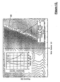
Figure 9 ) of either the signals or the differenced signals, thearray processor 146 determines the wavelength and so the (spatial) wavenumber k, and also the (temporal) frequency and so the angular frequency ω, of various of the spectral components of the stochastic parameter. There are numerous algorithms available in the public domain to perform the spatial/temporal decomposition of the array of pressure sensors 112-118. - Specifically, the
array processor 146 uses standard so-called beam forming, array processing, or adaptive array-processing algorithms, i.e. algorithms for processing the sensor signals using various delays and weighting to create suitable phase relationships between the signals provided by the different sensors, thereby creating phased antenna array functionality. In other words, the beam forming or array processing algorithms transform the time domain signals from the sensor array into their spatial and temporal frequency components, i.e. into a set of wave numbers given by k=2π/λ where λ is the wavelength of a spectral component, and corresponding angular frequencies given by ω=2πν. - One such technique of determining the speed of sound propagating through the
flow 102 involves using array processing techniques to define an acoustic ridge in the k-ω plane as shown inFigure 9 . The slope of the acoustic ridge is indicative of the speed of sound propagating through theflow 102. The speed of sound (SOS) is determined by applying sonar arraying processing techniques to determine the speed at which the one dimensionalacoustic waves 110 propagate past the axial array of unsteady pressure measurements distributed along thepipe 104. - The
apparatus 100 of the present invention measures the speed of sound (SOS) of one-dimensional sound waves 110 (seeFigure 5 ) propagating through themixture 102 to determine the gas volume fraction of themixture 102. It is known that sound propagates through various mediums at various speeds in such fields as SONAR and RADAR fields. The speed of sound propagating through thepipe 104 and flow 102 may be determined using a number of known techniques, such as those set forth inU.S. Patent Application Serial No. 09/344,094, filed June 25, 1999 US 6,354,147 ;U.S. Patent Application Serial No. 10/795,111, filed March 4, 2004 U.S. Patent Application Serial No. 09/997,221, filed November 28, 2001 US 6,587,798 ;U.S. Patent Application Serial No. 10/007,749 , filed November 7, 200 1, andU.S. Patent Application Serial No. 10/762,410, filed January 21, 2004 - In the case of suitable
acoustic waves 110 being present in both axial directions, the power in the k-ω plane shown in a k-ω plot ofFigure 9 so determined will exhibit a structure that is called anacoustic ridge acoustic ridges 150 is indicative of the speed of sound traveling in one axial direction and the otheracoustic ridge 152 being indicative of the speed of sound traveling in the other axial direction. - The
acoustic ridges flow 102 and is a mathematical manifestation of the relationship between the spatial variations and temporal variations described above. Such a plot will indicate a tendency for k-ω pairs to appear more or less along aline acoustic ridge identifier 154, which uses one or another feature extraction method to determine the location and orientation (slope) of anyacoustic ridge analyzer 156 determines the speed of sound of themixture 102 by using the slope of one of the twoacoustic ridges acoustic ridges - As shown in
Figure 1 andFigure 4 , theGVF logic 158 provides output signals indicative of gas volume or void fraction of themixture 102 in response to the measured speed of sound of themixture 102. For example, to determine the gas volume fraction (or phase fraction), theGVF logic 158 assumes a nearly isothermal condition for theflow 102. As such the gas volume fraction or the void fraction is related to the speed of sound by the following quadratic equation:
wherein x is the speed of sound, A=1+rg/r1*(Keff/P-1)-Keff/P, B=Keff/-2+rg/r1; C=1-Keff/r1*ameas^2); Rg = gas density, r1 = liquid density, Keff = effective K (modulus of the liquid and pipewall), P= pressure, and ameas = measured speed of sound. - Effectively,

- Alternatively, the sound speed of a mixture can be related to volumetric phase fraction (φi) of the components and the sound speed (a) and densities (p) of the component through the Wood equation.

- One dimensional compression waves propagating within a
mixture 102 contained within apipe 104 exerts an unsteady internal pressure loading on thepipe 104. The degree to which thepipe 104 displaces as a result of the unsteady pressure loading influences the speed of propagation of the compression wave. The relationship among the infinite domain speed of sound and density of a mixture, the elastic modulus (E), thickness (t), and radius (R) of a vacuum-backed cylindrical conduit, and the effective propagation velocity (a eff ) for one dimensional compression is given by the following expression:
- The mixing rule essentially states that the compressibility of a mixture (1/(ρ a2)) is the volumetrically-weighted average of the compressibilities of the components. For gas/
liquid mixtures 102 at pressure and temperatures typical of the paper and pulp industry, the compressibility of gas phase is orders of magnitudes greater than that of the liquid. Thus, the compressibility of the gas phase and the density of the liquid phase primarily determine mixture sound speed, and as such, it is necessary to have a good estimate of process pressure to interpret mixture sound speed in terms of volumetric fraction of entrained gas. The effect of process pressure on the relationship between sound speed and entrained air volume fraction is shown inFigure 10 . - Some or all of the functions within the
processing unit 108 may be implemented in software (using a microprocessor or computer) and/or firmware, or may be implemented using analog and/or digital hardware, having sufficient memory, interfaces, and capacity to perform the functions described herein. - As shown in
Figure 4 , themeasurement apparatus 100 includes asensing device 106 comprising an array of ultrasonic sensor units 120-126. Each sensor unit 120-126 comprises a pair ofultrasonic sensors outer surface 132 of thepipe 104 having aprocess flow 102 propagating therein. The pair ofsensors pipe 104 at predetermined locations along thepipe 104 to provide a through transmission configuration, such that the sensors transmit and receive an ultrasonic signal that propagates through the fluid substantially orthogonal to the direction of the flow of the fluid within thepipe 104. The ultrasonic measurement portion of the present invention is similar to that shown inU.S. Provisional Patent Application No. 10/756,977 - As shown in
Figure 1 , each pair ofultrasonic sensors sensor 160 to the receivingsensor 162. The transit time measurement or variation is indicative of coherent properties that convect with the flow within the pipe 104 (e.g., vortical disturbances, inhomogenieties within the flow, temperature variations, bubbles, particles, pressure disturbances), which are indicative of the velocity of theprocess flow 102. Theultrasonic sensors ultrasonic sensors flow 102. For instance, the larger the air bubbles in an aerated fluid the lower the desirable frequency of the ultrasonic signal. Examples of frequency used for a flow meter embodying the present invention are 1 MHz and 5 MHz. The ultrasonic sensors 160,162 may also provide a pulsed, chirped or continuous signal through thefluid flow 102. An example of thesensors - An
ultrasonic signal processor 164 fires thesensors transmitter 108 and receives the ultrasonic output signals S1(t) - SN(t) from thesensors signal processor 164 processes the data from each of the sensor units 120-126 to provide an analog or digital output signal T1(t) - TN(t) indicative of the time of flight or transit time of the ultrasonic signal through the fluid. Thesignal processor 164 may also provide an output signal indicative of the amplitude (or attenuation) of the ultrasonic signals. One such signal processor is model no. USPC 2100 manufactured by Krautkramer Ultrasonic Systems. Measuring the amplitude of ultrasonic signals is particularly useful and works best for measuring the velocity of a fluid that includes a substance in the flow (e.g., multiphase fluid or slurry). - The output signals (T1(t)- TN(t)) of the
ultrasonic signal processor 164 are provided to theprocessor 108, which processes the transit time or modulation measurement data to determine the volumetric flow rate. The transit time or time of flight measurement is defined by the time it takes for an ultrasonic signal to propagate from the transmittingsensor 160 to therespective receiving sensor 162 through the pipe wall and thefluid 102. The effect of the vortical disturbances (and/or other inhomogenities within the fluid) on the transit time of the ultrasonic signal is to delay or speed up the transit time. Therefore, each sensing unit 120-126 provides a respective output signal T1(t)-TN(t) indicative of the variations in the transit time of the ultrasonic signals propagating orthogonal to the direction of thefluid 102. The measurement is derived by interpreting the convecting coherent property and/or characteristic within the process piping using at least twosensor units outer surface 132 of the pipe 104 (e.g. contact or non-contact sensor). - In one example, the
flow meter 100 measures the volumetric flow rate by determining the velocity of vortical disturbances or "eddies" 168 (seeFigure 5 ) propagating with theflow 102 using the array of ultrasonic sensors 120-126. Theflow meter 100 measures the velocities associated with unsteady flow fields created by vortical disturbances or "eddies" 168 and other inhomogenities to determine the velocity of theflow 102. The ultrasonic sensor units 120-126 measure the transmit time T1(t)-TN(t) of the respective ultrasonic signals between each respective pair ofsensors flow 102 through thepipe 104 in a known manner. Therefore, the velocity of these vortical disturbances is related to the velocity of theflow 102 and hence the volumetric flow rate may be determined, as will be described in greater detail hereinafter. The volumetric flow is determined by multiplying the velocity of the fluid by the cross-sectional area of thepipe 104. - The
Flow Logic 170 of theprocessing unit 108 processes the ultrasonic signals as shown inFigure 11 , wherein theFlow Logic 170 receives the ultrasonic signals from the array of sensors 120-126. A data acquisition unit 172 (e.g., A/D converter) converts the analog signals to respective digital signals and the digitized signals are provided to Fast Fourier Transform (FFT)logic 174. TheFFT logic 174 calculates the Fourier transform of the digitized time-based input signals T1(t) - TN(t) and provides complex frequency domain (or frequency based) signals T1(ω), T2(ω), T3(ω), TN(ω) indicative of the frequency content of the input signals. It should be appreciated that instead of FFT's, any other technique for obtaining the frequency domain characteristics of the signals T1(t) - TN(t), may be used. For example, the cross-spectral density and the power spectral density may be used to form a frequency domain transfer functions (or frequency response or ratios) discussed hereinafter. - One technique of determining the convection velocity of the
turbulent eddies 168 within the process flow 102 (seeFigure 5 ) is by characterizing a convective ridge of the resulting unsteady pressures using an array of sensors or other beam forming techniques, similar to that described in U.S Patent Application, Serial No. (Cidra's Docket No. CC-0122A) andU.S. Patent Application, Serial No. 09/729,994 (Cidra's Docket No. CC-0297), filed December 4, 200, nowUS6,609,069 . - A
data accumulator 176 accumulates the frequency signals T1(ω) - TN(ω) over a sampling interval, and provides the data to anarray processor 178, which performs a spatial-temporal (two-dimensional) transform of the sensor data, from the xt domain to the k-ω domain, and then calculates the power in the k-ω plane, as represented by a k-ω plot. - The
array processor 178 uses standard so-called beam forming, array processing, or adaptive array-processing algorithms, i.e. algorithms for processing the sensor signals using various delays and weighting to create suitable phase relationships between the signals provided by the different sensors, thereby creating phased antenna array functionality. In other words, the beam forming or array processing algorithms transform the time domain signals from the sensor array into their spatial and temporal frequency components, i.e. into a set of wave numbers given by k=2π/λ where λ is the wavelength of a spectral component, and corresponding angular frequencies given by ω=2πν. - The prior art teaches many algorithms of use in spatially and temporally decomposing a signal from a phased array of sensors, and the present invention is not restricted to any particular algorithm. One particular adaptive array processing algorithm is the Capon method/algorithm. While the Capon method is described as one method, the present invention contemplates the use of other adaptive array processing algorithms, such as MUSIC algorithm. The present invention recognizes that such techniques can be used to determine flow rate, i.e. that the signals caused by a stochastic parameter convecting with a flow are time stationary and have a coherence length long enough that it is practical to locate sensor units apart from each other and yet still be within the coherence length.
- Convective characteristics or parameters have a dispersion relationship that can be approximated by the straight-line equation,

where u is the convection velocity (flow velocity). A plot of k-ω pairs obtained from a spectral analysis of sensor samples associated with convective parameters portrayed so that the energy of the disturbance spectrally corresponding to pairings that might be described as a substantially straight ridge, a ridge that in turbulent boundary layer theory is called a convective ridge. What is being sensed are not discrete events ofturbulent eddies 168, but rather a continuum of possibly overlapping events forming a temporally stationary, essentially white process over the frequency range of interest. In other words, theconvective eddies 168 is distributed over a range of length scales and hence temporal frequencies. - To calculate the power in the k-ω plane, as represented by a k-ω plot (see
Figure 12 ) of either the signals, thearray processor 178 determines the wavelength and so the (spatial) wavenumber k, and also the (temporal) frequency and so the angular frequency ω, of various of the spectral components of the stochastic parameter. There are numerous algorithms available in the public domain to perform the spatial/temporal decomposition of arrays of sensor units 120-126. - The present invention may use temporal and spatial filtering to precondition the signals to effectively filter out the common mode characteristics Pcommon mode and other long wavelength (compared to the sensor spacing) characteristics in the
pipe 104 by differencing adjacent sensors and retain a substantial portion of the stochastic parameter associated with the flow field and any other short wavelength (compared to the sensor spacing) low frequency stochastic parameters. - In the case of suitable turbulent eddies 168 (see
Figure 5 ) being present, the power in the k-ω plane shown in a k-ω plot ofFigure 12 shows aconvective ridge 180. Theconvective ridge 180 represents the concentration of a stochastic parameter that convects with theflow 102 and is a mathematical manifestation of the relationship between the spatial variations and temporal variations described above. Such a plot will indicate a tendency for k-ω pairs to appear more or less along aline 180 with some slope, the slope indicating the flow velocity. - Once the power in the k-ω plane is determined, a
convective ridge identifier 182 uses one or another feature extraction method to determine the location and orientation (slope) of anyconvective ridge 180 present in the k-ω plane. In one embodiment, a so-called slant stacking method is used, a method in which the accumulated frequency of k-ω pairs in the k-ω plot along different rays emanating from the origin are compared, each different ray being associated with a different trial convection velocity (in that the slope of a ray is assumed to be the flow velocity or correlated to the flow velocity in a known way). Theconvective ridge identifier 182 provides information about the different trial convection velocities, information referred to generally as convective ridge information. - The
analyzer 184 examines the convective ridge information including the convective ridge orientation (slope). Assuming the straight-line dispersion relation given by k=ω/u, theanalyzer 184 determines the flow velocity, Mach number and/or volumetric flow. The volumetric flow is determined by multiplying the cross-sectional area of the inside of thepipe 104 with the velocity of theprocess flow 102. - The watercut of the
process flow 102 is determined using the output of at least one of the sensors 120-126 of the ultrasonic flow meter. While anultrasonic sensor 120 of the ultrasonic meter is used to determine the watercut of theflow 102, it is contemplated that a separate ultrasonic sensor may be used to determine watercut. A separate ultrasonic sensor for measuring watercut would allow the sensor to transmit an ultrasonic signal at different frequencies to ensure the ultrasonic sensor for watercut is operating at a freguency greater than the bubble resonant frequency. - The
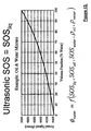
SOS Liquid Logic 186 converts the measured transit time of the ultrasonic signal to a signal indicative of the speed of sound of the liquid. The frequency of the ultrasonic signal propagating through the fluid is greater than the bubble resonant frequency such that the entrained gas does not affect the ultrasonic signal. Knowing the SOS of the liquid portion of thefluid flow 102, the phase fraction of the water can be determined. The phase fraction of the water is a function of the SOS of the liquid, the SOS of the oil, SOS of the water, the density of the oil, and the density of the water. Knowing the SOS and density of the oil and water, the relationship between the phase fraction (e.g., watercut) of theflow 102 and the SOS of the liquid is known. As shown inFigure 13 , this relationship is illustrated in the plot of SOS of the liquid v. watercut, and therefore, knowing the SOS of the liquid, the watercut may be determined. - While the sonar-based flow meter using an array of sensors to measure the speed of sound of an acoustic wave propagating through the
mixture 102 is shown and described, one will appreciate that any means for measuring the speed of sound of the acoustic wave may used to determine the entrained gas volume fraction of the mixture/fluid or other characteristics of theflow 102 described hereinbefore. - While
data acquisition units FFT logic data accumulators array processors ridge identifiers - While each of the ultrasonic sensor units 120-126 of
Figure 1 comprises a pair of ultrasonic sensors (transmitter and receiver) 160, 162 diametrically-opposed to provide through transmission, the present invention contemplates that one of theultrasonic sensors transmitter sensor 160 has an axial component in its propagation direction. - The present invention also contemplates the sensor units 120-126 of the
sensing device 106 may be configured in a pulse/echo configuration. In this embodiment, each sensing unit 120-126 comprises one ultrasonic sensor that transmits an ultrasonic signal through the pipe wall and fluid substantially orthogonal to the direction of flow and receives a reflection of the ultrasonic signal reflected back from the wall of the pipe to the ultrasonic sensor. - The
sensing device 106 may be configured to function in a pitch and catch configuration. In this embodiment, each sensor unit 120-126 comprises a pair of ultrasonic sensors (transmitter, receiver) 160, 162 disposed axially along thepipe 104 disposed on the same side of thepipe 104 at a predetermined distance apart. Eachtransmitter sensor 160 provides an ultrasonic signal at a predetermined angle into theflow 102. The ultrasonic signal propagates through the fluid 102 and reflects off the inner surface of thepipe 104 and reflects the ultrasonic signal back through the fluid to therespective receiver sensor 162. - As shown in
Figure 1 , while the ultrasonic sensor portion of theflow measurement device 100 comprises an array of ultrasonic sensor units 120-126 (seeFigure 5 ), the present invention contemplates that any ultrasonic meter or sensing portion may be used. The ultrasonic meter may be any meter within any of the three classes of flow meters that utilize ultrasonic transducers, which include transit time ultrasonic flow meters (TTUF), doppler ultrasonic flow meters (DUF), and cross correlation ultrasonic flow meters (CCUF). - The ultrasonic sensor portion may be any known ultra-sonic flow meter, such as
U.S. Patent No. 2,874,568 ;U.S. Patent No. 4,004,461 ;U.S. Patent No. 6,532,827 ;U.S. Patent No. 4,195,517 ;U.S. Patent No. 5,856,622 ; andU.S. Patent No. 6,397,683 . - It should be appreciated that the array-based
flow meter 100 is similar to that described inU.S Patent Application, Serial No. 10/007,749 filed November 7,2001 (Atty. Docket No. CC-0066B),U.S Patent Application, Serial No. 10/007,736 filed November 8, 2001 (Atty. Docket No. CC-0122A),U.S. Patent No. 6,587,798, filed on November 28,2001 , (Atty. Docket No. CC-0295),U.S. Provisional Patent Application, Serial No. 60/359,785 filed February 26, 2002 U.S Provisional Patent Application, Serial No. 60/425,436 filed November 12, 2002 U.S. Patent Application Serial No. 09/729,994, filed December 4, 2000 U.S. Patent Application, Serial No. 10,875,857 - While a
single array processor 108 is shown to receive and process input signals from the pressure sensors 112-118 and the ultrasonic sensors 120-126, the present invention contemplates that an array processor may be dedicated to each of the array of pressure sensors 112-118 and the array of ultra-sonic sensors 120-126. -
Figure 14 illustrates a block diagram of aflow measurement apparatus 200 similar to theapparatus 100 ofFigure 1 that includes a sensing device (sensor head) 106 mounted to apipe 104 and a processing unit or array processor (transmitter) 108, wherein theapparatus 200 functions as a GVF meter, a flow meter, and a watercut meter. In this embodiment, thesensor head 106 for the GVF meter functions as thesensor head 106 for both the GVF meter and flow meter ofFigure 1 . It should be appreciated that the processing of all the data is similar to that described hereinbefore and like reference numbers are the same elements and function the same as that described herein before. - Referring to
Figure 15 , thesensor head 106 includes an array of strained-based or pressure sensors 112-118. The signals provided by the pressure sensors 112-118 are processed to determine the gas volume (or void) fraction of theflow 102, the velocity of theflow 102, the volumetric flow rate, and speed of sound of the mixture (i.e., flow) 102. The combination GVF/flow meter, in accordance with the present invention, can determine the speed at which sound (i.e.,acoustic wave 110 inFigure 5 ) propagates through thefluid flow 102 within apipe 104 to measure the speed of sound of themixture 102 and the gas void (or volume) fraction of theflow 102. The GVF/flow meter also determines the speed at which pressure disturbances (e.g., vortical disturbances) propagate through thepipe 104 to determine the velocity of thefluid flow 102. The pressure disturbances may be in the form of vortical disturbances 168 (e.g.,turbulent eddies 168 inFigure 5 ) or other pressure disturbances that convect (or propagate) with theflow 102. - As suggested and further described in greater detail hereinafter, the
apparatus - 1) Determining the speed of sound of acoustical disturbances or sound waves propagating through the
flow 102 using the array of pressure sensors 112-118, and/or - 2) Determining the velocity of pressure disturbances (e.g., vortical eddies 168) propagating through the
flow 102 using the array of pressure sensors 112-118. - These techniques are similar to what was taught and described hereinbefore in reference to
Figure 8 and Figure 11 , respectively. Also, the processing relating to the watercut meter is similar to that described herein before. - One skilled in the art should appreciate that the watercut meter may also be used as a stand alone meter to enable a user to measure the watercut of a multiphase fluid flow having entrained air.
- The pressure sensors 112-118 and the ultrasonic sensors 120-126 shown in the
apparatus Figure 4 andFigure 15 , respectively, may be clamp-on, non-wetted sensors. These clamp-on sensors allow theapparatus apparatus - In one embodiment as shown in
Figure 4 andFigure 15 , each of the pressure sensors 112-118 may include a piezoelectric film attached to a unitary multi-band strap to measure the unsteady pressures of theflow 102 using either technique described hereinbefore. The piezoelectric film sensors 112-118 may be mounted onto a unitary substrate or web which is mounted or clamped onto theouter surface 132 of thepipe 104, which will described in greater detail hereinafter. - The piezoelectric film sensors 112-118 include a piezoelectric material or film 188 to generate an electrical signal proportional to the degree that the material is mechanically deformed or stressed. The piezoelectric sensing element 188 is typically conformed to allow complete or nearly complete circumferential measurement of induced strain to provide a circumferential-averaged pressure signal. The sensors can be formed from PVDF films, co-polymer films, or flexible PZT sensors, similar to that described in "Piezo Film Sensors Technical Manual" provided by Measurement Specialties, Inc., which is incorporated herein by reference. A piezoelectric film sensor that may be used for the present invention is part number 1-1002405-0, LDT4-028K, manufactured by Measurement Specialties, Inc. While the piezoelectric film material is provided substantially the length of the band, and therefore the circumference of the
pipe 104, the present invention contemplates that the piezoelectric film material may be disposed along a portion of the band of any length less than the circumference of thepipe 104. - Piezoelectric film ("piezofilm"), like piezoelectric material, is a dynamic material that develops an electrical charge proportional to a change in mechanical stress. Consequently, the piezoelectric material measures the strain induced within the
pipe 104 due to unsteady or stochastic pressure variations (e.g., vortical and/or acoustical) within theprocess flow 102. Strain within thepipe 104 is transduced to an output voltage or current by the attached piezoelectric sensor 112-118. The piezoelectrical material or film may be formed of a polymer, such as polarized fluoropolymer, polyvinylidene fluoride (PVDF). The piezoelectric film sensors are similar to that described inU.S. Patent Application Serial No. 10/712,818 U.S. Patent Application Serial No. 10/795,111 pipe 104 as individual sensors or all the sensors mounted as a single unit as shown inFigure 4 andFigure 15 . - The pressure sensors 112-118 of
Figure 4 described herein may be any type of sensor, capable of measuring the unsteady (or ac or dynamic) pressures or parameter that convects with the flow within apipe 104, such as piezoelectric, optical, capacitive, resistive (e.g., Wheatstone bridge), accelerometers (or geophones), velocity measuring devices, displacement measuring devices, ultra-sonic devices, etc. If optical pressure sensors are used, the sensors 112-118 may be Bragg grating based pressure sensors, such as that described inUS Patent Application, Serial No. 08/925,598 U.S. Patent 6,016,702 , and inUS Patent Application, Serial No. 10/224,821 , entitled " Non-Intrusive Fiber Optic Pressure Sensor for Measuring Unsteady Pressures within a Pipe". In an embodiment of the present invention that utilizes fiber optics as the pressure sensors 112-118 they may be connected individually or may be multiplexed along one or more optical fibers using wavelength division multiplexing (WDM), time division multiplexing (TDM), or any other optical multiplexing techniques. - In certain embodiments of the present invention, a piezo-electronic pressure transducer may be used as one or more of the pressure sensors 112-118 and it may measure the unsteady (or dynamic or ac) pressure variations inside the
pipe 104 by measuring the pressure levels inside of thepipe 104. These sensors may be ported within the pipe to make direct contact with theprocess flow 102. In an embodiment of the present invention, the sensors comprise pressure sensors manufactured by PCB Piezotronics. In one pressure sensor there are integrated circuit piezoelectric voltage mode-type sensors that feature built-in microelectronic amplifiers, and convert the high-impedance charge into a low-impedance voltage output. Specifically, a Model 106B manufactured by PCB Piezotronics is used which is a high sensitivity, acceleration compensated integrated circuit piezoelectric quartz pressure sensor suitable for measuring low pressure acoustic phenomena in hydraulic and pneumatic systems. - It is also within the scope of the present invention that any strain sensing technique may be used to measure the variations in strain in the
pipe 104, such as highly sensitive piezoelectric, electronic or electric, strain gages and piezo-resistive strain gages attached to thepipe 104. Other strain gages include resistive foil type gages having a race track configuration similar to that disclosedU.S. Patient Application Serial No. 09/344,094, filed June 25, 1999 US 6,354,147 . The invention also contemplates strain gages being disposed about a predetermined portion of the circumference ofpipe 104. The axial placement of and separation distance ΔX1, ΔX2 between the strain sensors are determined as described hereinabove. - It is also within the scope of the present invention that any other strain sensing technique may be used to measure the variations in strain in the
pipe 104, such as highly sensitive piezoelectric, electronic or electric, strain gages attached to or embedded in thepipe 104. - While the description has described the apparatus as a single meter that measure the GVF, Flow and watercut, each function may be separated into individual meters for measuring GVF, flow and watercut.
- Referring to
Figure 16 , the description and function of the gas volume fraction meter, the ultrasonic flow meter and the ultrasonic watercut meter of theflow apparatus 300 is similar to that described hereinbefore. The flow apparatus includes a density and/ormass flow meter 302, such as a coriolis meter, to provide measurements of different parameters of thefluid flow 102. For example, the combination of the coriolis meter and the gas volume fraction meter may be an augmented output measurement of the density, mass flow, net oil flow rate, and net water flow rate (for a flow comprising an aerated oil/water mixture). This combination is similar to that described inUS Patent Application No. 10/892,886 - For example, one approach at correcting inaccuracies in densitometers involves integrating a speed-of-sound measurement of the process fluid with the natural frequency measurement of a vibrating tube density meter to form a system with an enhanced ability to operate accurately in aerated fluids. Introducing a real time, speed-of-sound measurement address the effects of aeration on multiple levels with the intent to enable vibrating-tube-based density measurement to continue to report liquid density in the presence of entrained air with accuracy approaching that for a non-aerated liquid. Firstly, by measuring the process sound speed with process pressure, the aeration level of the process fluid can be determined with high accuracy on a real time basis. Secondly, the real time measurements of sound speed, and the derived measurement of gas volume fraction, are then utilized with empirically derived correction factors to improve the interpretation of the measured natural frequency of the vibrating tubes in terms of the density of the aerated fluid. Thirdly, the combined knowledge of aerated mixture density and aerated mixture sound speed, enable the determination of the non-aerated liquid component density, providing improved compositional information. Note liquids phase typically includes pure liquids, mixtures of liquids, as well as liquid / solid mixtures.
- For densitometers, such as a Corilois meter, a decrease in the accuracy of the measurments with the introduction of bubbly fluids is well documented. In fact, others have attempted to correct for the effect of entrained air by correlating observed terrors in mass flow to the gas volume fraction within the process fluid. These authors proposed a correction based on GVF as follows:

where α represents the gas volume fraction and R represents decrease in measured (apparent) mass flow normalized by the true mass flow. Thus, using this correlation, a 1% increase in entrained air would result in a roughly 2% underestimate of the actual mass flow. Although this formulation appears to capture the general trend observed experimentally, it has two drawbacks for use in the field. Firstly, the Coriolis meter typically has no direct way to measure the gas volume fraction. It has been suggested to use the measured apparent density of the fluid to estimate the level of entrained air, however, this is problematic since both of the two fundamental measurements, phase difference and natural frequency, are impacted by changes in the reduced frequency of the Coriolis vibration. Secondly, it is unlikely that the gas volume fraction is the only variable influencing the relationship between measured phase difference and mass flow and the measured natural frequency and density. Although gas volume fraction appears to correlate over at least some range of parameters, the physics of the problem suggest that sound speed, via a reduced frequency effect, may also have a direct influence on the data interpretation. - One method would be to use a direct sound measurement from the process fluid to aid in the interpretation of the Coriolis meter. In this interpretation, the reduced frequency parameters developed herein is included in interpreting the relation between the phase difference in the vibrating tubes and the mass flow as well as a direct role in interpreting the natural frequency of the oscillating flow tubes in terms of process fluid density. The sound speed measurement, combined with knowledge of process liquid and gas components as well as process temperature and pressure, enables a direct measurement of entrained air as well. Thus, the reduced frequency parameter and gas volume fraction can be used as inputs in the interpretation of phase lag in terms of mass flow. Due to the strong relationship between air content in liquids and mixture sound speed, the role of the reduced frequency parameter in the interpretation of the fundamental measurement of the Coriolis meter will have a more pronounce effect in bubbly flows. However, changes in sound speed and hence reduced frequency of operation in various types of liquids and other process mixtures have an effect on the interpretation and hence accuracy of Coriolis meter used in these applications as well. Consider, for example, the performance of a Coriolis meter on two liquids - water and oil. Assuming that the fluids have different densities and sound speeds, the different fluid properties suggest that the Coriolis meter will be operating at different reduced frequencies. The reduced frequency for the water will typically be ∼10%-30% lower than that for the oil application. Recognizing that, while they are different, the reduced frequencies for both applications are still "small", the impact on accuracy may not be significant. However, some degree of inaccuracy is introduced by not accounting for the differences in the reduced frequency of operation of the Coriolis meter in this application. For other density meter, such as a nuclear densitometer, these meters may corrected simply knowing the gas volume fraction (or gas void fraction) of the fluid .
- Referring to
Figure 17 , a clamp-on three phaseflow measurement apparatus 310 is shown that provides a phase fraction measurement of the fluid flow and a volumetric flow rate of each of the phases of theflow 102. The flow may be full or partially full (i.e., stratified). The clamp onapparatus 310 comprises aflow meter 312 having a plurality of strained-based sensors disposed longitudinally along thepipe 104 similar to that shown inFigure 15 . Theflow meter 312 processes the data from the array of sensors similar to that described hereinbefore as indicated in the flow logic of theprocessing unit 108 ofFigure 15 andFigure 12 , to provide a fluid flow velocity. The clamp-onapparatus 310 further includes a clamp ondensity meter 314, such as a nuclear densitometer, wherein the sensors of the densitometer are positioned or oriented at approximately 6 and 12 o'clock or top and bottom of thepipe 104 to ensure the radiant beam pass through both gas and liquid of a stratified flow. The densitometer provides a density measurement, which is used to determine the gas volume fraction of the 3-phase fluid. The clamp-onapparatus 310 further includes at least oneultrasonic sensor 316 for determining the watercut of the liquid phase of the threephase fluid 102. Thesensor 316 is disposed orthogonal to the sensors of the densitometer at 3 and 9 o'clock or in the horizontal position to ensure the ultrasonic beam or signal propagates primarily through the liquid of a stratified fluid flow. The data and/or sensed signals of the three clamped ondevices flow computer 320 which processes the data using amultiphase flow model 400 to provide threephase flow measurements 402 of thefluid flow 102, such as compositional data (e.g., phase fraction of each phase of the fluid), velocity of each phase of the fluid 102, volumetric flow rate of each phase, and mass flow rate of each phase. It should be appreciated that themultiphase flow model 400 receives the flow data from eachdevice flow measurement data 402. - Referring again to
Figure 17 , although the sensors of the densitometer 314 (and thus the beam direction) are shown as being disposed vertically in a six o'clock and twelve o'clock position relative to theflow 102, it should be appreciated that the sensors (and thus beam) of thedensitometer 314 may be disposed in any orientation relative to theflow 102 suitable to the desired end purpose. For stratified flows, a gamma densitometer may be sensitive to stratification when the beam is traversing the fluid flow in the vertical direction. In effect the densitometer measures the height of an interface rather than the holdup or gas volume fraction. By rotating the densitometer a small amount, the sensitivity of the densitometer to the stratification or partially filled pipe is reduced. Rotating the beam off the vertical axis by approximately 26.5 degrees has shown an improvement in the measurement. -
Figure 18 illustrates a schematic diagram of well surveillance system, wherein the input and output flows of a fluid separator is provided. Specifically, the clamp-onmultiphase measurement apparatus 310 ofFigure 17 is used to measure the flow passing within the input pipe of the separator. The measurement apparatus ofFigure 16 is provided on the liquid leg of the separator for measuring the parameters of the aerated liquid mixture (e.g., aerated oil and water mixture). The gas leg of the separator includes a wet-gas flow measurement device similar to that described inUS Provisional Patent Application No. 60/724,952 US Provisional Patent Application No. 60/697,479 Figure 18 further includes aflow meter 318 comprising an array of ultrasonic sensors similar to that shown and described inFigure 1 ,Figure 4 andFigure 16 . Theflow meter 318 may be used in combination with thepassive flow meter 312 and differential pressure (DP) meter, or simply in combination with the DP meter. - One will appreciate that while each of the apparatus includes devices in a particular order on the pipe, one will appreciate that the device may be disposed in any order.
- The dimensions and/or geometries for any of the embodiments described herein are merely for illustrative purposes and, as such, any other dimensions and/or geometries may be used if desired, depending on the application, size, performance, manufacturing requirements, or other factors, in view of the teachings herein.
- It should be understood that, unless stated otherwise herein, any of the features characteristics, alternatives or modifications described regarding a particular embodiment herein may also be applied, used, or incorporated with any other embodiment described herein. Also, the drawings herein are not drawn to scale.
- Although the invention has been described and illustrated with respect to exemplary embodiments thereof, the foregoing and various other additions and omissions may be made therein and thereto without departing from the scope of the present invention.
Claims (9)
- An apparatus for determining a characteristic of an aerated fluid (102) flowing within a pipe (104), the apparatus comprising:at least one first sensing device (112-118, 120-126) associated with the pipe to sense a low-frequency component and a high-frequency component of the aerated fluid flow, wherein said at least one first sensing device generates first sensor data responsive to said low-frequency component of the aerated fluid indicative of speed of sound at frequencies below a bubble resonant frequency being a transition frequency below which the speed of sound propagating through the fluid is influenced by entrained gases and above which the entrained gases have no significant influence, and second sensor data indicative of a volumetric flow rate responsive to said high-frequency component of the aerated fluid flow;at least one second sensing device (302) associated with the pipe to sense a density or mass flow of the aerated fluid flow and to generate third sensor data indicative of a density or a mass flow rate responsive to said density or mass flow measurement of the aerated fluid flow; anda processing device (108), wherein said processing device is communicated with said at least one first sensing device and said at least one second sensing device to receive and process said first sensor data, said second sensor data and said third sensor data to generate fluid data responsive to a characteristic of the aerated fluid flow.
- The apparatus of claim 1, wherein said characteristic of the aerated fluid flow is at least one of a Gas Volume Fraction (GVF), a volumetric flow rate, a WaterCut value indicative of a phase fraction of water, a liquid flow rate and a net/oil/water rate.
- The apparatus of claim 1, wherein said second sensor data is responsive to the density or mass flow measurement and the speed of sound through a liquid component of the fluid flow.
- The apparatus of claim 1, wherein said at least one first sensing device includes a plurality of sensing devices (112-118, 120-126), wherein said plurality of sensing devices are axially distributed along the pipe.
- The apparatus of claim 1, wherein said at least one first sensing device includes a transmitting device (TX) and a receiving device (RX), wherein when said transmitting device and said receiving device are associated with the pipe, said transmitting device and said receiving device are disposed on opposing sides of the pipe.
- The apparatus of claim 1, wherein the apparatus includes a fastening device for removably and securely associating the apparatus with the pipe, wherein the fastening device is configured for easy removal and installation.
- The apparatus of claim 1, wherein the apparatus is securely associated with an external portion of the pipe via a clamp-on device.
- The apparatus of claim 1, wherein
the aerated fluid is a three phase multiphase fluid;
the at least one first sensing device, includes a flow sensing device (318, 312, 314) and a watercut sensing device (316) for sensing a watercut value indicative of a phase fraction of water;
the at least one second sensing device includes a density sensing device (302);
the processing device (108,320) including multiphase flow model logic (400), wherein said processing device (108,320) configured to receive flow rate data from said flow sensing device (312,318), density data from said density sensing device (302), and watercut data from said watercut sensing device (316),
wherein the multiphase flow model logic (400) receives the data from each of the flow, density and watercut sensing devices and processes the data to optimize and correct for any errors, inaccuracies, and/or various flow conditions or regimes,
wherein the fluid data is three phase flow measurement data output by said multiphase flow model logic (400). - The apparatus of claim 8, wherein the flow sensing device, the density sensing device and the watercut sensing device are secured to the outer surface of the pipe.
Applications Claiming Priority (2)
| Application Number | Priority Date | Filing Date | Title |
|---|---|---|---|
| US75838206P | 2006-01-11 | 2006-01-11 | |
| PCT/US2007/000872 WO2007089412A2 (en) | 2006-01-11 | 2007-01-10 | An apparatus and method for measuring a parameter of a multiphase flow |
Publications (2)
| Publication Number | Publication Date |
|---|---|
| EP1982169A2 EP1982169A2 (en) | 2008-10-22 |
| EP1982169B1 true EP1982169B1 (en) | 2012-11-07 |
Family
ID=38325366
Family Applications (1)
| Application Number | Title | Priority Date | Filing Date |
|---|---|---|---|
| EP07762897A Active EP1982169B1 (en) | 2006-01-11 | 2007-01-10 | Apparatus and method for measuring parameters of a multiphase fluid flow |
Country Status (4)
| Country | Link |
|---|---|
| EP (1) | EP1982169B1 (en) |
| CA (1) | CA2637011C (en) |
| NO (1) | NO340150B1 (en) |
| WO (1) | WO2007089412A2 (en) |
Families Citing this family (11)
| Publication number | Priority date | Publication date | Assignee | Title |
|---|---|---|---|---|
| US7401530B2 (en) * | 2006-05-11 | 2008-07-22 | Weatherford/Lamb, Inc. | Sonar based multiphase flowmeter |
| AT509641B1 (en) * | 2011-06-24 | 2012-08-15 | Avl List Gmbh | METHOD FOR DETERMINING FLUX FLOW AFTER ULTRASONIC TIME METHOD |
| US9880044B2 (en) | 2011-11-14 | 2018-01-30 | Street Smart Sensors Llc | Acoustic array sensor |
| AT510675B1 (en) * | 2012-02-23 | 2013-04-15 | Avl List Gmbh | Method for identifying the transmission behavior of a system, and ultrasonic transit time method for determining the flow rate in a medium |
| US9285261B2 (en) | 2012-09-12 | 2016-03-15 | Street Smart Sensors Llc | Acoustic flexural order level sensor |
| GB2507368B (en) | 2013-04-30 | 2016-01-06 | Iphase Ltd | Method and apparatus for monitoring the flow of mixtures of fluids in a pipe |
| US9500576B2 (en) | 2013-10-08 | 2016-11-22 | Yokogawa Corporation Of America | Systems and methods for determining a volumetric flow of a liquid portion of a multiphase fluid flow |
| US11226218B2 (en) | 2013-11-08 | 2022-01-18 | Schlumberger Technology Corporation | Flow regime recognition for flow model adaptation |
| WO2015070008A1 (en) | 2013-11-08 | 2015-05-14 | Schlumberger Canada Limited | Spectral analysis with spectrum deconvolution |
| CN104089665A (en) * | 2014-06-26 | 2014-10-08 | 卢玖庆 | Single-pipe three-phase flowmeter |
| CN110291366B (en) * | 2019-03-20 | 2020-12-25 | 深圳市汇顶科技股份有限公司 | Time-of-flight generating circuit and related chip, flowmeter and method |
Family Cites Families (8)
| Publication number | Priority date | Publication date | Assignee | Title |
|---|---|---|---|---|
| FR2522153A1 (en) * | 1982-02-19 | 1983-08-26 | Framatome Sa | ULTRASONIC MEASUREMENT METHOD FOR THE VOLUME OF GAS PRESENT IN AN ENCLOSURE COMPRISING A LIQUID-GAS MIXTURE AT THE TOTAL VOLUME OF THE ENCLOSURE |
| NO166379C (en) * | 1987-12-18 | 1991-07-10 | Sensorteknikk As | PROCEDURE FOR REGISTERING MULTIPHASE FLOWS THROUGH A TRANSPORT SYSTEM. |
| US5259250A (en) * | 1990-05-14 | 1993-11-09 | Atlantic Richfield Company | Multi-phase fluid flow mesurement |
| US6318156B1 (en) * | 1999-10-28 | 2001-11-20 | Micro Motion, Inc. | Multiphase flow measurement system |
| US6672163B2 (en) * | 2000-03-14 | 2004-01-06 | Halliburton Energy Services, Inc. | Acoustic sensor for fluid characterization |
| CA2513094C (en) * | 2002-11-12 | 2013-08-06 | Mark R. Fernald | An apparatus having an array of clamp on piezoelectric film sensors for measuring parameters of a process flow within a pipe |
| US7188534B2 (en) * | 2003-02-10 | 2007-03-13 | Invensys Systems, Inc. | Multi-phase coriolis flowmeter |
| ATE528623T1 (en) * | 2004-05-17 | 2011-10-15 | Expro Meters Inc | DEVICE AND METHOD FOR MEASURING THE COMPOSITION OF A MIXTURE FLOWING IN A TUBE |
-
2007
- 2007-01-10 EP EP07762897A patent/EP1982169B1/en active Active
- 2007-01-10 CA CA2637011A patent/CA2637011C/en active Active
- 2007-01-10 WO PCT/US2007/000872 patent/WO2007089412A2/en active Application Filing
-
2008
- 2008-08-06 NO NO20083442A patent/NO340150B1/en unknown
Also Published As
| Publication number | Publication date |
|---|---|
| CA2637011C (en) | 2016-06-14 |
| WO2007089412A2 (en) | 2007-08-09 |
| NO20083442L (en) | 2008-10-03 |
| CA2637011A1 (en) | 2007-08-09 |
| NO340150B1 (en) | 2017-03-13 |
| EP1982169A2 (en) | 2008-10-22 |
| WO2007089412A3 (en) | 2007-12-27 |
Similar Documents
| Publication | Publication Date | Title |
|---|---|---|
| US7526966B2 (en) | Apparatus and method for measuring a parameter of a multiphase flow | |
| EP1886098B1 (en) | An apparatus and method for measuring a parameter of a multiphase flow | |
| EP1982169B1 (en) | Apparatus and method for measuring parameters of a multiphase fluid flow | |
| US7430924B2 (en) | Flow measurement apparatus having strain-based sensors and ultrasonic sensors | |
| US7380438B2 (en) | Apparatus and method for providing a fluid cut measurement of a multi-liquid mixture compensated for entrained gas | |
| US8061186B2 (en) | System and method for providing a compositional measurement of a mixture having entrained gas | |
| US7127360B2 (en) | Dual function flow measurement apparatus having an array of sensors | |
| EP1751503B1 (en) | Apparatus and method for measuring the composition of a mixture flowing in a pipe | |
| US7596987B2 (en) | Apparatus and method for providing a density measurement augmented for entrained gas | |
| US20040144182A1 (en) | Apparatus and method for providing a flow measurement compensated for entrained gas | |
| US20070055464A1 (en) | System and method for providing a compositional measurement of a mixture having entrained gas | |
| CA2537933C (en) | An apparatus and method for providing a density measurement augmented for entrained gas | |
| EP1565709B1 (en) | An apparatus and method for providing a flow measurement compensated for entrained gas |
Legal Events
| Date | Code | Title | Description |
|---|---|---|---|
| PUAI | Public reference made under article 153(3) epc to a published international application that has entered the european phase |
Free format text: ORIGINAL CODE: 0009012 |
|
| 17P | Request for examination filed |
Effective date: 20080807 |
|
| AK | Designated contracting states |
Kind code of ref document: A2 Designated state(s): AT BE BG CH CY CZ DE DK EE ES FI FR GB GR HU IE IS IT LI LT LU LV MC NL PL PT RO SE SI SK TR |
|
| 17Q | First examination report despatched |
Effective date: 20090120 |
|
| RTI1 | Title (correction) |
Free format text: APPARATUS AND METHOD FOR MEASURING PARAMETERS OF A MULTIPHASE FLUID FLOW |
|
| GRAP | Despatch of communication of intention to grant a patent |
Free format text: ORIGINAL CODE: EPIDOSNIGR1 |
|
| DAX | Request for extension of the european patent (deleted) | ||
| GRAS | Grant fee paid |
Free format text: ORIGINAL CODE: EPIDOSNIGR3 |
|
| GRAA | (expected) grant |
Free format text: ORIGINAL CODE: 0009210 |
|
| AK | Designated contracting states |
Kind code of ref document: B1 Designated state(s): AT BE BG CH CY CZ DE DK EE ES FI FR GB GR HU IE IS IT LI LT LU LV MC NL PL PT RO SE SI SK TR |
|
| REG | Reference to a national code |
Ref country code: GB Ref legal event code: FG4D |
|
| REG | Reference to a national code |
Ref country code: CH Ref legal event code: EP Ref country code: AT Ref legal event code: REF Ref document number: 583205 Country of ref document: AT Kind code of ref document: T Effective date: 20121115 |
|
| REG | Reference to a national code |
Ref country code: IE Ref legal event code: FG4D |
|
| REG | Reference to a national code |
Ref country code: DE Ref legal event code: R096 Ref document number: 602007026561 Country of ref document: DE Effective date: 20130103 |
|
| REG | Reference to a national code |
Ref country code: AT Ref legal event code: MK05 Ref document number: 583205 Country of ref document: AT Kind code of ref document: T Effective date: 20121107 |
|
| REG | Reference to a national code |
Ref country code: NL Ref legal event code: VDEP Effective date: 20121107 |
|
| REG | Reference to a national code |
Ref country code: LT Ref legal event code: MG4D |
|
| PG25 | Lapsed in a contracting state [announced via postgrant information from national office to epo] |
Ref country code: IS Free format text: LAPSE BECAUSE OF FAILURE TO SUBMIT A TRANSLATION OF THE DESCRIPTION OR TO PAY THE FEE WITHIN THE PRESCRIBED TIME-LIMIT Effective date: 20130307 Ref country code: LT Free format text: LAPSE BECAUSE OF FAILURE TO SUBMIT A TRANSLATION OF THE DESCRIPTION OR TO PAY THE FEE WITHIN THE PRESCRIBED TIME-LIMIT Effective date: 20121107 Ref country code: ES Free format text: LAPSE BECAUSE OF FAILURE TO SUBMIT A TRANSLATION OF THE DESCRIPTION OR TO PAY THE FEE WITHIN THE PRESCRIBED TIME-LIMIT Effective date: 20130218 Ref country code: SE Free format text: LAPSE BECAUSE OF FAILURE TO SUBMIT A TRANSLATION OF THE DESCRIPTION OR TO PAY THE FEE WITHIN THE PRESCRIBED TIME-LIMIT Effective date: 20121107 Ref country code: FI Free format text: LAPSE BECAUSE OF FAILURE TO SUBMIT A TRANSLATION OF THE DESCRIPTION OR TO PAY THE FEE WITHIN THE PRESCRIBED TIME-LIMIT Effective date: 20121107 Ref country code: NL Free format text: LAPSE BECAUSE OF FAILURE TO SUBMIT A TRANSLATION OF THE DESCRIPTION OR TO PAY THE FEE WITHIN THE PRESCRIBED TIME-LIMIT Effective date: 20121107 |
|
| PG25 | Lapsed in a contracting state [announced via postgrant information from national office to epo] |
Ref country code: PT Free format text: LAPSE BECAUSE OF FAILURE TO SUBMIT A TRANSLATION OF THE DESCRIPTION OR TO PAY THE FEE WITHIN THE PRESCRIBED TIME-LIMIT Effective date: 20130307 Ref country code: PL Free format text: LAPSE BECAUSE OF FAILURE TO SUBMIT A TRANSLATION OF THE DESCRIPTION OR TO PAY THE FEE WITHIN THE PRESCRIBED TIME-LIMIT Effective date: 20121107 Ref country code: BE Free format text: LAPSE BECAUSE OF FAILURE TO SUBMIT A TRANSLATION OF THE DESCRIPTION OR TO PAY THE FEE WITHIN THE PRESCRIBED TIME-LIMIT Effective date: 20121107 Ref country code: GR Free format text: LAPSE BECAUSE OF FAILURE TO SUBMIT A TRANSLATION OF THE DESCRIPTION OR TO PAY THE FEE WITHIN THE PRESCRIBED TIME-LIMIT Effective date: 20130208 Ref country code: CY Free format text: LAPSE BECAUSE OF FAILURE TO SUBMIT A TRANSLATION OF THE DESCRIPTION OR TO PAY THE FEE WITHIN THE PRESCRIBED TIME-LIMIT Effective date: 20121107 Ref country code: LV Free format text: LAPSE BECAUSE OF FAILURE TO SUBMIT A TRANSLATION OF THE DESCRIPTION OR TO PAY THE FEE WITHIN THE PRESCRIBED TIME-LIMIT Effective date: 20121107 Ref country code: SI Free format text: LAPSE BECAUSE OF FAILURE TO SUBMIT A TRANSLATION OF THE DESCRIPTION OR TO PAY THE FEE WITHIN THE PRESCRIBED TIME-LIMIT Effective date: 20121107 |
|
| PG25 | Lapsed in a contracting state [announced via postgrant information from national office to epo] |
Ref country code: AT Free format text: LAPSE BECAUSE OF FAILURE TO SUBMIT A TRANSLATION OF THE DESCRIPTION OR TO PAY THE FEE WITHIN THE PRESCRIBED TIME-LIMIT Effective date: 20121107 |
|
| PG25 | Lapsed in a contracting state [announced via postgrant information from national office to epo] |
Ref country code: CZ Free format text: LAPSE BECAUSE OF FAILURE TO SUBMIT A TRANSLATION OF THE DESCRIPTION OR TO PAY THE FEE WITHIN THE PRESCRIBED TIME-LIMIT Effective date: 20121107 Ref country code: BG Free format text: LAPSE BECAUSE OF FAILURE TO SUBMIT A TRANSLATION OF THE DESCRIPTION OR TO PAY THE FEE WITHIN THE PRESCRIBED TIME-LIMIT Effective date: 20130207 Ref country code: DK Free format text: LAPSE BECAUSE OF FAILURE TO SUBMIT A TRANSLATION OF THE DESCRIPTION OR TO PAY THE FEE WITHIN THE PRESCRIBED TIME-LIMIT Effective date: 20121107 Ref country code: SK Free format text: LAPSE BECAUSE OF FAILURE TO SUBMIT A TRANSLATION OF THE DESCRIPTION OR TO PAY THE FEE WITHIN THE PRESCRIBED TIME-LIMIT Effective date: 20121107 Ref country code: EE Free format text: LAPSE BECAUSE OF FAILURE TO SUBMIT A TRANSLATION OF THE DESCRIPTION OR TO PAY THE FEE WITHIN THE PRESCRIBED TIME-LIMIT Effective date: 20121107 |
|
| PG25 | Lapsed in a contracting state [announced via postgrant information from national office to epo] |
Ref country code: IT Free format text: LAPSE BECAUSE OF FAILURE TO SUBMIT A TRANSLATION OF THE DESCRIPTION OR TO PAY THE FEE WITHIN THE PRESCRIBED TIME-LIMIT Effective date: 20121107 Ref country code: RO Free format text: LAPSE BECAUSE OF FAILURE TO SUBMIT A TRANSLATION OF THE DESCRIPTION OR TO PAY THE FEE WITHIN THE PRESCRIBED TIME-LIMIT Effective date: 20121107 Ref country code: MC Free format text: LAPSE BECAUSE OF NON-PAYMENT OF DUE FEES Effective date: 20130131 |
|
| REG | Reference to a national code |
Ref country code: CH Ref legal event code: PL |
|
| PLBE | No opposition filed within time limit |
Free format text: ORIGINAL CODE: 0009261 |
|
| STAA | Information on the status of an ep patent application or granted ep patent |
Free format text: STATUS: NO OPPOSITION FILED WITHIN TIME LIMIT |
|
| 26N | No opposition filed |
Effective date: 20130808 |
|
| REG | Reference to a national code |
Ref country code: IE Ref legal event code: MM4A |
|
| REG | Reference to a national code |
Ref country code: FR Ref legal event code: ST Effective date: 20130930 |
|
| PG25 | Lapsed in a contracting state [announced via postgrant information from national office to epo] |
Ref country code: LI Free format text: LAPSE BECAUSE OF NON-PAYMENT OF DUE FEES Effective date: 20130131 Ref country code: CH Free format text: LAPSE BECAUSE OF NON-PAYMENT OF DUE FEES Effective date: 20130131 Ref country code: DE Free format text: LAPSE BECAUSE OF NON-PAYMENT OF DUE FEES Effective date: 20130801 |
|
| REG | Reference to a national code |
Ref country code: DE Ref legal event code: R119 Ref document number: 602007026561 Country of ref document: DE Effective date: 20130801 |
|
| PG25 | Lapsed in a contracting state [announced via postgrant information from national office to epo] |
Ref country code: FR Free format text: LAPSE BECAUSE OF NON-PAYMENT OF DUE FEES Effective date: 20130131 |
|
| PG25 | Lapsed in a contracting state [announced via postgrant information from national office to epo] |
Ref country code: IE Free format text: LAPSE BECAUSE OF NON-PAYMENT OF DUE FEES Effective date: 20130110 |
|
| PG25 | Lapsed in a contracting state [announced via postgrant information from national office to epo] |
Ref country code: TR Free format text: LAPSE BECAUSE OF FAILURE TO SUBMIT A TRANSLATION OF THE DESCRIPTION OR TO PAY THE FEE WITHIN THE PRESCRIBED TIME-LIMIT Effective date: 20121107 |
|
| PG25 | Lapsed in a contracting state [announced via postgrant information from national office to epo] |
Ref country code: LU Free format text: LAPSE BECAUSE OF NON-PAYMENT OF DUE FEES Effective date: 20130110 Ref country code: HU Free format text: LAPSE BECAUSE OF FAILURE TO SUBMIT A TRANSLATION OF THE DESCRIPTION OR TO PAY THE FEE WITHIN THE PRESCRIBED TIME-LIMIT; INVALID AB INITIO Effective date: 20070110 |
|
| P01 | Opt-out of the competence of the unified patent court (upc) registered |
Effective date: 20230512 |
|
| PGFP | Annual fee paid to national office [announced via postgrant information from national office to epo] |
Ref country code: GB Payment date: 20231130 Year of fee payment: 18 |