EP0087365B1 - Method for the ultrasonic measuring of the relationship between the volume of gas present in an enclosure containing a liquid-gas mixture end the total volume of the enclosure - Google Patents
Method for the ultrasonic measuring of the relationship between the volume of gas present in an enclosure containing a liquid-gas mixture end the total volume of the enclosure Download PDFInfo
- Publication number
- EP0087365B1 EP0087365B1 EP83400344A EP83400344A EP0087365B1 EP 0087365 B1 EP0087365 B1 EP 0087365B1 EP 83400344 A EP83400344 A EP 83400344A EP 83400344 A EP83400344 A EP 83400344A EP 0087365 B1 EP0087365 B1 EP 0087365B1
- Authority
- EP
- European Patent Office
- Prior art keywords
- gas
- liquid
- enclosure
- propagation
- void coefficient
- Prior art date
- Legal status (The legal status is an assumption and is not a legal conclusion. Google has not performed a legal analysis and makes no representation as to the accuracy of the status listed.)
- Expired
Links
Images


Classifications
-
- G—PHYSICS
- G01—MEASURING; TESTING
- G01N—INVESTIGATING OR ANALYSING MATERIALS BY DETERMINING THEIR CHEMICAL OR PHYSICAL PROPERTIES
- G01N29/00—Investigating or analysing materials by the use of ultrasonic, sonic or infrasonic waves; Visualisation of the interior of objects by transmitting ultrasonic or sonic waves through the object
- G01N29/02—Analysing fluids
- G01N29/024—Analysing fluids by measuring propagation velocity or propagation time of acoustic waves
-
- G—PHYSICS
- G01—MEASURING; TESTING
- G01N—INVESTIGATING OR ANALYSING MATERIALS BY DETERMINING THEIR CHEMICAL OR PHYSICAL PROPERTIES
- G01N2291/00—Indexing codes associated with group G01N29/00
- G01N2291/02—Indexing codes associated with the analysed material
- G01N2291/028—Material parameters
- G01N2291/02872—Pressure
Definitions
- the invention relates to a method of ultrasonic measurement of the ratio of the volume of gas present in an enclosure containing a two-phase liquid gas mixture to the total volume of the enclosure or vacuum rate, the gas not dissolved in the liquid being in the form of '' a layer on top of the liquid and / or in the form of bubbles distributed in the liquid.
- the primary circuit of pressurized water nuclear reactors contains, when the reactor is in operation, water at a very high pressure of the order of 155 bars and at a temperature of the order of 310 ° C.
- the difficulty of this measurement is increased by the fact that the vapor produced in the primary circuit can be in the form of bubbles distributed inside the primary water, in the form of a layer of vapor surmounting the water not vaporized or in both forms simultaneously.
- the use of ultrasonic waves is known for determining different physical parameters of a fluid in an enclosure or a pipe, by measurement of attenuation or propagation time.
- the patent application DE-A-2 217 308 discloses a method for measuring the proportion of free air not dissolved in the pressurized liquid of a hydraulic installation, by measuring the propagation speed d in the liquid.
- Such measurement methods or devices cannot be used for determining the vacuum rate in the primary circuit of a nuclear reactor, the two-phase mixture contained in this primary circuit, in the event of an accident, may be in different forms. and variable over time. It is also necessary, in the case of monitoring the primary circuit of a nuclear reactor, to know very quickly the vacuum rate whatever the form in which the vapor is present in the primary circuit during decompression.
- the object of the invention is to propose a first method of ultrasonic measurement of the ratio of the volume of gas present in an enclosure containing a two-phase liquid-gas mixture to the total volume of the enclosure, said ratio being hereinafter called the rate of total vacuum, the gas not dissolved in the liquid being in the form of a layer surmounting the liquid and / or in the form of bubbles distributed in the liquid, this process having to allow a very rapid determination of the vacuum rate whatever the form under which the gas is present inside the enclosure.
- the vacuum rate is determined without using to capture the waves reflected by the gas-liquid interface.
- the relationships existing between the height of a possible gas layer above the liquid containing the gas bubbles are used, the velocities of the ultrasonic waves in the gas and the liquid-gas bubble mixture and the propagation times of the gases. waves through the fluid filling the enclosure as well as the relationship between the velocities of the waves in the liquid-gas bubbles mixture, for each of the frequencies, determined beforehand by calibration, as a function of the vacuum rate due to the gas bubbles. From these relationships, the vacuum rate due to the gas bubbles distributed in the liquid, the height of gas in the enclosure and the vacuum rate due to the gas overcoming the liquid are determined.
- the total vacuum rate is then determined by adding the vacuum rate due to the gas overlying the liquid and the vacuum rate due to the gas bubbles distributed in the liquid.
- a second method according to the invention in the case where all the gas is only in the form of bubbles distributed in the liquid is described in claim 4.
- This distribution of water and steam is in this form, for example in a container originally containing pressurized water which has undergone partial depressurization and vaporization.
- the vapor is only in the form of bubbles distributed inside the liquid which is not surmounted by any layer of vapor.
- the vapor bubbles distributed in the water disappear and there is a certain amount of water on mounted by a stratified vapor layer.
- the vapor layer increases until the water has completely evaporated.
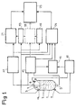
- transducers 4, 5, 6 and 7 On the enclosure and on either side thereof in the vertical direction and in a neighboring direction are arranged transducers 4, 5, 6 and 7 making it possible to emit and collect ultrasonic waves through the filling fluid the enclosure 1. Between the transducers 4 and 5, the straight distance over which the ultrasonic waves propagate is practically identical to the length over which the waves propagate between the transducers 6 and 7.
- the transducers 6 and 7 allow the emission and reception of an ultrasonic wave at low frequency, of the order of 1 KHz.
- the transducers 4 and 5 allow the emission and reception of ultrasonic waves at high frequency of the order of 1 M Hz.
- the transducer 4 also makes it possible to collect on return the ultrasonic waves emitted in the vertical direction, after reflection on the upper level 8 of the water containing the bubbles.
- Calculation units 10 and 11 make it possible to determine the propagation time in the fluid filling the enclosure, high frequency waves and low frequency waves respectively.
- a computer 12 allows the calculation of the difference between the propagation times of low frequency waves and high frequency waves.
- the speed of propagation of ultrasonic waves in a homogeneous medium is independent of the frequency of these waves.
- a pressure sensor 14 inside the container 1 makes it possible to determine the equilibrium pressure of the steam and of the water in this container. This pressure corresponds to a well-determined value of the temperature of the fluid in enclosure 1.
- the vapor contained in the container 1 is in its entirety in the form of a layer overlying the water under pressure not sprayed.
- calculation units 15 and 16 make it possible to determine the speed of the ultrasound in steam and in water at the pressure measured by the sensor 14.
- the length of the ultrasound path in the vapor which is simply linked to the vacuum rate in the enclosure can be very easily determined from the propagation time of the waves and the velocities of the ultrasound in the vapor and in the at the pressure considered.
- the overall vacuum rate is equal to the vacuum rate due to the vapor in the stratified phase obtained by means of the calculation unit 18.
- a second way of obtaining the vacuum rate is to collect by means of the transducer 4 the ultrasonic waves reflected by the surface 8 of the water, after a course representing twice the height h of the layer of vapor above water in enclosure 1.
- a calculation unit 20 makes it possible to determine the propagation time of the ultrasonic waves in the vapor, the length of the path of these ultrasonic waves being equal to 2 h.
- the calculation unit 21 makes it possible to determine from the propagation time of the waves in the steam supplied by the calculation unit 20 and from the speed of the ultrasound in the steam at the pressure considered supplied by the calculation unit 15, the vacuum rate due to the vapor in the stratified phase above the water. This value is equal to the accuracy of the measurement close to the value obtained using the calculation unit 18.
- FIG. 2 the variations of the speed of sound are shown in a stratified water-vapor mixture filling a horizontal cylindrical pipe as a function of the vacuum rate a and for different pressures of the fluid filling the pipe corresponding to well-determined temperatures of this fluid.
- a calculation unit having in memory the equations of the curves as represented in FIG. 2 and for a sufficient number of pressures to allow extrapolation leads to the immediate determination of the vacuum rate a from the time of propagation of the ultrasonic waves in the pipe containing water surmounted by steam.
- the vapor is at least partially in the form of bubbles distributed in non-vaporized water.
- the presence of a liquid-vapor interface 8 can be determined by capturing the reflected wave possibly on the surface 8, thanks to the transducer 4.
- the calculation unit 20 already described makes it possible to calculate the propagation time of the waves in the vapor, following a round trip between the transducer 4 and the level 8.
- Such curves can be stored in large quantities in a calculation unit 24 receiving as input data the propagation time of the high frequency waves determined by the calculation unit 10, the propagation time of the waves in the vapor, in coming from the calculation unit 20 and the pressure of the fluid filling the enclosure 1. From these input data and the relationships or graphs stored in memory, the calculation unit 24 makes it possible to determine the speed of the high waves frequency in water containing bubbles of vapor and the rate of vacuum due to the vapor in the form of bubbles.
- This vacuum rate is added to the vacuum rate due to the vapor in the stratified phase calculated by the unit 21, in a computer 25.
- the computer 25 can then give the value of the overall vacuum rate in the enclosure 1.
- the processing by the calculation unit 24 is triggered when a difference is detected at the level of the calculation unit 12 between the propagation times of the low and high frequency waves.
- a calculation unit is used for this purpose, having in memory the curves or relationships between the propagation speed of the waves and the frequency in a mixture of water and vapor bubbles, according to the pressure and according to the vacuum rate. Such curves are shown in FIG. 3.
- L designates the length of the wave path throughout the crossing of the container 1
- V being the speed of the ultrasonic waves in the vapor at the pressure considered
- Ci (BF) and C 1 ((HF) the speeds of the ultrasonic waves in the liquid containing the bubbles at the pressure considered, for the low frequency and high waves frequency, respectively.
- the input data to the calculation unit are the propagation times ⁇ t BF and ⁇ t HF, the pressure and the speed of propagation of the ultrasound in the vapor, which makes it possible to determine the value of the height h of the vapor layer and the vacuum rate due to the vapor bubbles in the water.
- the vacuum rate due to the stratified vapor and the overall vacuum rate is deduced by the calculation unit by adding this vacuum rate due to the stratified steam and the vacuum rate due to the steam bubbles in water.
- This apparatus comprises two pairs of transducers 32, 33 and 34, 35 arranged in a diagonally opposite manner on the pipe 30.
- the pair of transducers 32-33 allows the emission and the capture of an ultrasonic wave at a first frequency, while the pair of transducers 34-35 allows the emission and the capture of an ultrasonic wave at a second frequency.
- the propagation times of these ultrasonic waves in the fluid filling the pipe 30 are calculated by calculation units 36 and 37.
- a calculation unit 38 makes it possible to calculate the ratio between the difference in wave propagation times and the difference in frequency logarithms.
- a pressure sensor 40 is arranged inside the pipe 30 to supply a signal representative of the pressure of the fluid filling the pipe 30 to a calculation unit 42 also receiving from the calculation unit 38 a signal representative of the ratio of the differences in travel time unlike frequencies of ultrasonic waves.
- the calculation unit 42 a stored in memory, the relationships between ultrasonic wave speed and frequency, according to the different vacuum rates and according to the different pressures, determined by calibration and as shown, for example according to FIG. 3.
- the calculation unit 42 allows a comparison of the ratio with the slope of the curves giving the variation of the speed of sound as a function of frequency.
- the frequencies F1 and F2 are relatively close, so that the comparison of the slopes and the ratio is done in the vicinity of one of the frequencies or of an average frequency. This makes it possible to determine the void rate since, as can be seen in FIG. 3, the slopes of the curves vary greatly with the void rate.
- the measurement of the void rate can therefore be done very quickly using relatively close frequencies for the two ultrasonic waves.
- This simplified method of determining the vacuum rate is very useful in the first phases following a rupture on the primary circuit of a pressurized water reactor.
- the safety systems are designed in such a way that it is entirely unlikely that an accident could lead to vaporization with the formation of a stratified vapor layer.
- the device can make it possible to determine the proportion of gas in a liquid contained in an enclosure or a pipe.
- the invention is not limited to the embodiments which have been described.
- the enclosure contains a liquid having gas bubbles in suspension
- the frequencies of the ultrasonic waves and the paths of these inside the fluid it is possible to choose in any way the frequencies of the ultrasonic waves and the paths of these inside the fluid.
- the process according to the invention applies not only in the case of the determination of the vacuum rate in the primary circuit of a pressurized water nuclear reactor but also in the case of any pressurized liquid capable of vaporizing. and even in the case of any liquid which may contain a gas in a variable proportion.
Description
L'invention concerne un procédé de mesure par ultrasons du rapport du volume de gaz présent dans une enceinte contenant un mélange diphasique liquide gaz au volume total de l'enceinte ou taux de vide, le gaz non dissous dans le liquide se présentant sous forme d'une couche surmontant le liquide et/ou sous forme de bulles réparties dans le liquide.The invention relates to a method of ultrasonic measurement of the ratio of the volume of gas present in an enclosure containing a two-phase liquid gas mixture to the total volume of the enclosure or vacuum rate, the gas not dissolved in the liquid being in the form of '' a layer on top of the liquid and / or in the form of bubbles distributed in the liquid.
Le circuit primaire des réacteurs nucléaires à eau sous pression renferme, lorsque le réacteur est en fonctionnement, de l'eau à une très forte pression de l'ordre de 155 bars et à une température de l'ordre de 310 °C.The primary circuit of pressurized water nuclear reactors contains, when the reactor is in operation, water at a very high pressure of the order of 155 bars and at a temperature of the order of 310 ° C.
Dans le cas d'une rupture sur une canalisation du circuit primaire, la pression de cette eau tombe très rapidement et une vaporisation au moins partielle de l'eau primaire se produit. On utilise alors le circuit d'injection de sécurité du réacteur pour éviter un échauffement trop important du coeur ou des autres parties du circuit primaire.In the event of a rupture on a primary circuit pipe, the pressure of this water falls very quickly and at least partial vaporization of the primary water occurs. The safety injection circuit of the reactor is then used to avoid excessive heating of the core or of the other parts of the primary circuit.
Dans les instants qui suivent une rupture sur le circuit primaire, il est extrêmement important, pour évaluer l'effet des mesures de sécurité prises et en particulier l'effet de l'injection d'eau dans le circuit primaire, de mesurer la proportion de vapeur présente dans le fluide réfrigérant.In the moments following a rupture on the primary circuit, it is extremely important, to evaluate the effect of the safety measures taken and in particular the effect of the injection of water into the primary circuit, to measure the proportion of vapor present in the refrigerant.
Il est par exemple important de connaître le rapport du volume de vapeur contenu dans une canalisation du circuit primaire au volume total de cette canalisation, après une rupture. Ce rapport, appelé taux de vide, peut bien sûr évoluer très rapidement après la rupture, en fonction de la gravité de cette rupture et de l'efficacité des mesures de sécurité déclenchées automatiquement ou mises en oeuvre par l'opérateur conduisant la centrale.It is for example important to know the ratio of the volume of vapor contained in a pipe of the primary circuit to the total volume of this pipe, after a rupture. This ratio, called the vacuum rate, can of course change very quickly after the failure, depending on the severity of this failure and the effectiveness of the safety measures triggered automatically or implemented by the operator operating the power plant.
On ne connaissait pas jusqu'ici de procédé extrêmement rapide et extrêmement sûr de détermination du taux de vide dans une partie du circuit primaire d'un réacteur nucléaire.An extremely rapid and extremely reliable method for determining the vacuum rate in a part of the primary circuit of a nuclear reactor has not hitherto been known.
En effet, la difficulté de cette mesure est accrue par le fait que la vapeur produite dans le circuit primaire peut se présenter sous forme de bulles réparties à l'intérieur de l'eau primaire, sous forme d'une couche de vapeur surmontant l'eau non vaporisée ou encore sous les deux formes simultanément.Indeed, the difficulty of this measurement is increased by the fact that the vapor produced in the primary circuit can be in the form of bubbles distributed inside the primary water, in the form of a layer of vapor surmounting the water not vaporized or in both forms simultaneously.
On admet généralement que si la vaporisation se poursuit dans le circuit primaire, jusqu'à devenir totale, on rencontre au cours du temps des phases successives où la vapeur est d'abord sous forme de bulles réparties dans l'eau, puis sous forme de bulles réparties dans l'eau et sous forme d'une couche surmontant le mélange eau-bulles de vapeur, puis d'une couche de vapeur de plus en plus importante surmontant l'eau ne renfermant plus de bulles de gaz.It is generally accepted that if the vaporization continues in the primary circuit, until it becomes total, we meet over time successive phases where the vapor is first in the form of bubbles distributed in the water, then in the form of bubbles distributed in water and in the form of a layer overlying the water-vapor bubble mixture, then an increasingly large layer of vapor overcoming the water, no longer containing gas bubbles.
Il est donc très difficile d'imaginer une méthode de mesure du taux de vide permettant de traiter tous ces cas différents.It is therefore very difficult to imagine a method for measuring the void rate allowing all these different cases to be treated.
De façon plus générale, lorsqu'un gaz est introduit dans une enceinte qui normalement ne renferme qu'un liquide, ce gaz étant sous forme de bulles réparties dans le liquide, sous forme d'une couche surmontant le liquide ou simultanément sous ces deux formes, il peut être extrêmement intéressant de connaître le rapport du volume de gaz au volume total de l'enceinte, pour connaître, par exemple, l'importance d'une fuite et déterminer les actions à entreprendre à la suite de cet incident.More generally, when a gas is introduced into an enclosure which normally only contains a liquid, this gas being in the form of bubbles distributed in the liquid, in the form of a layer surmounting the liquid or simultaneously in these two forms , it can be extremely interesting to know the ratio of the volume of gas to the total volume of the enclosure, to know, for example, the importance of a leak and determine the actions to be taken following this incident.
Il est d'autre part tout-à-fait exclu de pouvoir accéder directement au fluide disposé à l'intérieur de l'enceinte, ce fluide étant généralement à très haute pression et à très haute température.On the other hand, it is entirely excluded to be able to directly access the fluid disposed inside the enclosure, this fluid generally being at very high pressure and at very high temperature.
On connaît d'autre part l'utilisation des ondes ultrasonores pour la détermination de différents paramètres physiques d'un fluide dans une enceinte ou une canalisation, par mesure d'atténuation ou de temps de propagation. Par exemple, on connaît par la demande de brevet DE-A-2 217 308, un procédé de mesure de la proportion d'air libre non dissous dans le liquide sous pression d'une installation hydraulique, par mesure de la vitesse de propagation d'ultrasons dans le liquide.On the other hand, the use of ultrasonic waves is known for determining different physical parameters of a fluid in an enclosure or a pipe, by measurement of attenuation or propagation time. For example, the patent application DE-A-2 217 308 discloses a method for measuring the proportion of free air not dissolved in the pressurized liquid of a hydraulic installation, by measuring the propagation speed d in the liquid.
On connaît également, par le brevet US-A-4 135 387, un dispositif de surveillance de la proportion d'eau dans la vapeur utilisée dans une installation de production d'énergie. Pour pouvoir effectuer cette surveillance par une simple mesure de vitesse de propagation d'ondes soniques ou ultrasoniques, on effectue dans un premier temps une homogénéisation du mélange eau-vapeur grâce à un premier générateur d'ondes soniques ou ultrasoniques. Un second générateur d'ondes soniques ou ultrasoniques associé à un détecteur de temps de propagation permet de mesurer la vitesse de propagation des ondes émises dans le fluide homogénéisé.Also known, from US-A-4,135,387, a device for monitoring the proportion of water in the steam used in an energy production installation. In order to be able to carry out this monitoring by a simple measurement of the speed of propagation of sonic or ultrasonic waves, a homogenization of the water-vapor mixture is first carried out using a first generator of sonic or ultrasonic waves. A second generator of sonic or ultrasonic waves associated with a propagation time detector makes it possible to measure the propagation speed of the waves emitted in the homogenized fluid.
De tels procédés ou dispositifs de mesure ne sont pas utilisables pour la détermination du taux de vide dans le circuit primaire d'un réacteur nucléaire, le mélange diphasique contenu dans ce circuit primaire, en cas d'accident, pouvant se présenter sous des formes différentes et variables au cours du temps. Il est de plus nécessaire, dans le cas de la surveillance du circuit primaire d'un réacteur nucléaire, de connaître très rapidement le taux de vide quelle que soit la forme sous laquelle la vapeur se présente dans le circuit primaire en cours de décompression.Such measurement methods or devices cannot be used for determining the vacuum rate in the primary circuit of a nuclear reactor, the two-phase mixture contained in this primary circuit, in the event of an accident, may be in different forms. and variable over time. It is also necessary, in the case of monitoring the primary circuit of a nuclear reactor, to know very quickly the vacuum rate whatever the form in which the vapor is present in the primary circuit during decompression.
Le but de l'invention est de proposer un premier procédé de mesure par ultrasons du rapport du volume de gaz présent dans une enceinte contenant un mélange diphasique liquide-gaz au volume total de l'enceinte, ledit rapport étant ci-après appelé taux de vide total, le gaz non dissous dans le liquide se présentant sous forme d'une couche surmontant le liquide et/ou sous forme de bulles réparties dans le liquide, ce procédé devant permettre une détermination très rapide du taux de vide quelle que soit la forme sous laquelle se présente le gaz à l'intérieur de l'enceinte.The object of the invention is to propose a first method of ultrasonic measurement of the ratio of the volume of gas present in an enclosure containing a two-phase liquid-gas mixture to the total volume of the enclosure, said ratio being hereinafter called the rate of total vacuum, the gas not dissolved in the liquid being in the form of a layer surmounting the liquid and / or in the form of bubbles distributed in the liquid, this process having to allow a very rapid determination of the vacuum rate whatever the form under which the gas is present inside the enclosure.
Dans ce but:
- a) on provoque la propagation, à travers ledit mélange, d'une première onde ultrasonore ayant une première fréquence, suivant un premier parcours peu incliné par rapport à une section verticale de cette enceinte et traversant celle-ci,
- b) on provoque la propagation, à travers ledit mélange, d'une seconde onde ultrasonore ayant une seconde fréquence différente de ladite première fréquence, suivant un second parcours voisin dudit premier parcours,
- c) on mesure la pression d'équilibre dudit mélange diphasique liquide-gaz, ou un paramètre physique directement lié à cette pression,
- d) on mesure les temps de propagation des première et seconde ondes ultrasonores sur leur parcours respectif, on compare ces temps de propagation et, si ceux-ci sont égaux à un temps de propagation ci-après dénommé temps de propagation commun,
- d1 ) on calcule, grâce au résultat de ladite mesure de pression d'équilibre, les vitesses de propagation des ondes ultrasonores, à cette pression d'équilibre d'une part dans le gaz, et d'autre part dans le liquide,
- d2) on détermine enfin le taux de vide total à partir dudit temps de propagation commun et desdites vitesses de propagation,
- e) alors que, si lesdits temps de propagation sont différents,
- e1) on détermine la présence ou l'absence d'une onde ultrasonore réfléchie par l'interface gaz-liquide dudit mélange et si, cette onde réfléchie est présente, on mesure son temps de propagation dans le gaz,
- e2) on calcule, grâce au résultat de ladite mesure de pression d'équilibre, la vitesse de propagation des ondes ultrasonores à cette pression d'équilibre dans le gaz,
- e3) on détermine le taux de vide dû à la couche de gaz à partir dudit temps de propagation dans le gaz de l'onde ultrasonore réfléchie et de ladite vitesse de propagation des ondes ultrasonores dans le gaz,
- e4) on calcule la vitesse de propagation de l'une au moins des première et seconde ondes ultrasonores à travers le liquide,
- e5) on détermine, à partir de cette dernière vitesse de propagation et en utilisant les relations connues existant entre ladite pression d'équilibre, la fréquence des ondes ultrasonores et cette même vitesse de propagation dans le liquide, le taux de vide dû aux bulles de gaz réparties dans le liquide,
- e6) on calcule enfin le taux de vide total par addition dudit taux de vide dû à la couche de gaz et dudit taux de vide dû aux bulles de gaz réparties dans le liquide.
- a) provoking the propagation, through said mixture, of a first ultrasonic wave having a first frequency, following a first by course slightly inclined with respect to a vertical section of this enclosure and crossing it,
- b) a second ultrasonic wave having a second frequency different from said first frequency is propagated through said mixture, along a second path close to said first path,
- c) the equilibrium pressure of said two-phase liquid-gas mixture, or a physical parameter directly related to this pressure, is measured,
- d) the propagation times of the first and second ultrasonic waves are measured over their respective paths, these propagation times are compared and, if these are equal to a propagation time hereinafter called the common propagation time,
- d1) the propagation velocities of the ultrasonic waves are calculated, thanks to the result of said equilibrium pressure measurement, at this equilibrium pressure on the one hand in the gas, and on the other hand in the liquid,
- d2) finally, the total vacuum rate is determined from said common propagation time and said propagation speeds,
- e) whereas, if said propagation times are different,
- e1) the presence or absence of an ultrasonic wave reflected by the gas-liquid interface of said mixture is determined and if this reflected wave is present, its propagation time in the gas is measured,
- e2) the speed of propagation of the ultrasonic waves at this equilibrium pressure in the gas is calculated, thanks to the result of said equilibrium pressure measurement,
- e3) the vacuum rate due to the gas layer is determined from said propagation time in the gas of the reflected ultrasonic wave and from said propagation speed of the ultrasonic waves in the gas,
- e4) the speed of propagation of at least one of the first and second ultrasonic waves through the liquid is calculated,
- e5) on the basis of this latter propagation speed and using the known relationships existing between said equilibrium pressure, the frequency of the ultrasonic waves and this same propagation speed in the liquid, the vacuum rate due to the bubbles gases distributed in the liquid,
- e6) finally calculating the total vacuum rate by adding said vacuum rate due to the gas layer and said vacuum rate due to gas bubbles distributed in the liquid.
Suivant une variante, dans le cas où les temps de propagation des ondes ultrasonores sont différents, une partie au moins du gaz étant sous forme de bulles réparties dans le liquide et en équilibre avec celui-ci, on détermine le taux de vide sans avoir recours au captage des ondes réfléchies par l'interface gaz-liquide.According to a variant, in the case where the propagation times of the ultrasonic waves are different, at least part of the gas being in the form of bubbles distributed in the liquid and in equilibrium with it, the vacuum rate is determined without using to capture the waves reflected by the gas-liquid interface.
On utilise pour celà les relations existant entre la hauteur d'une couche de gaz éventuelle au-dessus du liquide renfermant les bulles de gaz, les vitesses des ondes ultrasonores dans le gaz et le mélange liquide-bulles de gaz et les temps de propagation des ondes à travers le fluide remplissant l'enceinte ainsi que la relation entre les vitesses des ondes dans le mélange liquide-bulles de gaz, pour chacune des fréquences, déterminée préalablement par étalonnage, en fonction du taux de vide dû aux bulles de gaz. A partir de ces relations, on détermine le taux de vide dû aux bulles de gaz réparties dans le liquide, la hauteur de gaz dans l'enceinte et le taux de vide dû au gaz surmontant le liquide.For this, the relationships existing between the height of a possible gas layer above the liquid containing the gas bubbles are used, the velocities of the ultrasonic waves in the gas and the liquid-gas bubble mixture and the propagation times of the gases. waves through the fluid filling the enclosure as well as the relationship between the velocities of the waves in the liquid-gas bubbles mixture, for each of the frequencies, determined beforehand by calibration, as a function of the vacuum rate due to the gas bubbles. From these relationships, the vacuum rate due to the gas bubbles distributed in the liquid, the height of gas in the enclosure and the vacuum rate due to the gas overcoming the liquid are determined.
On détermine ensuite le taux de vide total par addition du taux de vide dû au gaz surmontant le liquide et du taux de vide dû aux bulles de gaz réparties dans le liquide.The total vacuum rate is then determined by adding the vacuum rate due to the gas overlying the liquid and the vacuum rate due to the gas bubbles distributed in the liquid.
Un deuxième procédé suivant l'invention, dans le cas où tout le gaz est uniquement sous forme de bulles réparties dans le liquide est décrit dans la revendication 4.A second method according to the invention, in the case where all the gas is only in the form of bubbles distributed in the liquid is described in claim 4.
Afin de bien faire comprendre l'invention, on va maintenant décrire à titre d'exemples les deux suivant l'invention dans le cas d'une enceinte renfermant de l'eau sous pression partiellement vaporisée, la vapeur pouvant se présenter sous forme d'une couche surmontant le liquide et/ou de bulles de gaz réparties dans le liquide et dans le cas d'une canalisation renfermant de l'eau sous pression et de la vapeur sous forme de bulles de gaz réparties dans cette eau sous pression.
- La figure 1 représente de façon schématique une installation permettant la détermination du taux de vide dans une enceinte.
- La figure 2 est une représentation des variations de la vitesse du son dans un mélange stratifié eau-vapeur, en fonction du taux de vide, suivant la pression du mélange eau-vapeur.
- La figure 3 représente, pour trois valeurs de la pression et de la température différentes de l'eau sous pression, les variations de la vitesse du son en fonction de la fréquence d'une onde ultrasonore se propageant dans de l'eau renfermant des bulles de vapeur, suivant le taux de vide.
- La figure 4 représente, da façon schématique, une installation pour la mesure du taux de vide dans une canalisation renfermant de l'eau sous pression contenant des bulles de vapeur.
- Figure 1 shows schematically an installation for determining the vacuum rate in an enclosure.
- FIG. 2 is a representation of the variations in the speed of sound in a stratified water-vapor mixture, as a function of the vacuum rate, according to the pressure of the water-vapor mixture.
- FIG. 3 represents, for three different pressure and temperature values of the pressurized water, the variations in the speed of sound as a function of the frequency of an ultrasonic wave propagating in water containing bubbles steam, depending on the vacuum rate.
- Figure 4 shows, schematically, an installation for measuring the vacuum rate in a pipe containing pressurized water containing steam bubbles.
Sur la figure 1, on voit une enceinte 1 renfermant de l'eau et de la vapeur, celle-ci étant à la fois sous forme de bulles 2 réparties dans l'eau et sous forme d'une couche 3 surmontant l'eau non vaporisée.In Figure 1, we see an
Cette répartition de l'eau et de la vapeur se présente sous cette forme par exemple dans un récipient renfermant à l'origine de l'eau sous pression qui a subi une dépressurisation et une vaporisation partielles.This distribution of water and steam is in this form, for example in a container originally containing pressurized water which has undergone partial depressurization and vaporization.
Ceci représente le second stade de la vaporisation.This represents the second stage of vaporization.
Dans le premier stade, la vapeur est uniquement sous forme de bulles réparties à l'intérieur du liquide qui n'est surmonté par aucune couche de vapeur.In the first stage, the vapor is only in the form of bubbles distributed inside the liquid which is not surmounted by any layer of vapor.
Dans un troisième stade, les bulles de vapeur réparties dans l'eau disparaissent et l'on se trouve en présence d'une certaine quantité d'eau surmontée par une couche de vapeur stratifiée. La couche de vapeur augmente jusqu'à la vaporisation complète de l'eau.In a third stage, the vapor bubbles distributed in the water disappear and there is a certain amount of water on mounted by a stratified vapor layer. The vapor layer increases until the water has completely evaporated.
Sur l'enceinte et de part et d'autre de celle-ci suivant la direction verticale et suivant une direction voisine sont disposés des transducteurs 4, 5, 6 et 7 permettant d'émettre et de capter des ondes ultrasonores à travers le fluide remplissant l'enceinte 1. Entre les transducteurs 4 et 5, la distance rectiligne sur laquelle les ondes ultrasonores se propagent est pratiquement identique à la longueur sur laquelle les ondes se propagent entre les transducteurs 6 et 7.On the enclosure and on either side thereof in the vertical direction and in a neighboring direction are arranged
Les transducteurs 6 et 7 permettent l'émission et la réception d'une onde ultrasonore à basse fréquence, de l'ordre de 1 KHz. Les transducteurs 4 et 5 permettent l'émission et la réception d'ondes ultrasonores à haute fréquence de l'ordre de 1 M Hz.The
Le transducteur 4 permet de plus de capter au retour les ondes ultrasonores émises dans la direction verticale, après réflexion sur le niveau supérieur 8 de l'eau renfermant les bulles.The transducer 4 also makes it possible to collect on return the ultrasonic waves emitted in the vertical direction, after reflection on the upper level 8 of the water containing the bubbles.
Des unités de calculs 10 et 11 permettent de déterminer le temps de propagation dans le fluide remplissant l'enceinte, des ondes haute fréquence et des ondes basse fréquence respectivement.
Un calculateur 12 permet le calcul de la différence entre les temps de propagation des ondes basse fréquence et des ondes haute fréquence.A
La vitesse de propagation des ondes ultrasonores dans un milieu homogène, tel que l'eau et la vapeur, est indépendante de la fréquence de ces ondes.The speed of propagation of ultrasonic waves in a homogeneous medium, such as water and steam, is independent of the frequency of these waves.
En revanche, ces vitesse sont variables en fonction de la pression du fluide dans lequel elles se propagent.However, these speeds are variable depending on the pressure of the fluid in which they propagate.
Un capteur de pression 14 à l'intérieur du récipient 1 permet de déterminer la pression d'équilibre de la vapeur et de l'eau dans ce récipient. Cette pression correspond à une valeur bien déterminée de la température du fluide dans l'enceinte 1.A
Lorsqu'une onde se propage dans de l'eau renfermant des bulles de vapeur sa vitesse de propagation dépend de sa fréquence et augmente avec cette fréquence.When a wave propagates in water containing vapor bubbles its speed of propagation depends on its frequency and increases with this frequency.
Si la différence des temps de propagation 0 t B F - L t HF dans le mélange diphasique liquide-gaz est nulle on peut en conclure que la vapeur contenue dans le récipient 1 est dans son intégralité sous forme d'une couche surmontant l'eau sous pression non vaporisée.If the difference in propagation times 0 t BF - L t HF in the two-phase liquid-gas mixture is zero, it can be concluded that the vapor contained in the
On peut alors déterminer le taux de vide dans le récipient 1 de deux façons différentes.We can then determine the vacuum level in the
a) A partir de la valeur de la pression mesurée par le capteur 14, des unités de calcul 15 et 16 permettent de déterminer la vitesse des ultrasons dans la vapeur et dans l'eau à la pression mesurée par le capteur 14.a) From the value of the pressure measured by the
A partir de ces valeurs des vitesses des ultrasons et du temps de propagation dans ledit mélange calculé par exemple par l'unité de calcul 10, on peut déterminer, grâce à une unité de calcul 18, le taux de vide dû à la vapeur surmontant l'eau dans l'enceinte 1 .From these values of the ultrasonic velocities and the propagation time in said mixture calculated for example by the
En effet, la longueur du parcours des ultrasons dans la vapeur qui est reliée de façon simple au taux de vide dans l'enceinte peut être déterminée très facilement à partir du temps de propagation des ondes et des vitesses des ultrasons dans la vapeur et dans l'eau à la pression considérée.Indeed, the length of the ultrasound path in the vapor which is simply linked to the vacuum rate in the enclosure can be very easily determined from the propagation time of the waves and the velocities of the ultrasound in the vapor and in the at the pressure considered.
Dans le cas où les temps de propagation à haute et basse fréquences sont égaux, le taux de vide global est égal au taux de vide dû à la vapeur en phase stratifiée obtenu au moyen de l'unité de calcul 18.In the case where the propagation times at high and low frequencies are equal, the overall vacuum rate is equal to the vacuum rate due to the vapor in the stratified phase obtained by means of the
b) Une seconde façon d'obtenir le taux de vide est de capter au moyen du transducteur 4 les ondes ultrasonores réfléchies par la surface 8 de l'eau, après un parcours représentant deux fois la hauteur h de la couche de vapeur au-dessus de l'eau dans l'enceinte 1.b) A second way of obtaining the vacuum rate is to collect by means of the transducer 4 the ultrasonic waves reflected by the surface 8 of the water, after a course representing twice the height h of the layer of vapor above water in
Une unité de calcul 20 permet de déterminer le temps de propagation des ondes ultrasonores dans la vapeur, la longueur du trajet de ces ondes ultrasonores étant égale à 2 h.A
L'unité de calcul 21 permet de déterminer à partir du temps de propagation des ondes dans la vapeur fourni par l'unité de calcul 20 et à partir de la vitesse des ultrasons dans la vapeur à la pression considérée fournie par l'unité de calcul 15, le taux de vide dû à la vapeur en phase stratifiée au-dessus de l'eau. Cette valeur est égale à la précision de la mesure près à la valeur obtenue grâce à l'unité de calcul 18.The
Sur la figure 2, on a représenté les variations de la vitesse du son dans un mélange stratifié eau-vapeur remplissant une conduite cylindrique horizontale en fonction du taux de vide a et pour différentes pressions du fluide remplissant la conduite correspondant à des températures bien déterminées de ce fluide.In FIG. 2, the variations of the speed of sound are shown in a stratified water-vapor mixture filling a horizontal cylindrical pipe as a function of the vacuum rate a and for different pressures of the fluid filling the pipe corresponding to well-determined temperatures of this fluid.
Dans ce cas, il suffit de connaître la vitesse de propagation des ondes ultrasonores (ou le temps de propagation dans la conduite) ainsi que la pression du fluide pour déterminer de façon certaine le taux de vide dans la conduite.In this case, it is sufficient to know the speed of propagation of the ultrasonic waves (or the time of propagation in the pipe) as well as the pressure of the fluid to determine with certainty the vacuum rate in the pipe.
Une unité de calcul ayant en mémoire les équations des courbes telles que représentées à la figure 2 et pour un nombre de pressions suffisant pour permettre l'extrapolation conduit à la détermination immédiate du taux de vide a à partir du temps de propagation des ondes ultrasonores dans la conduite renfermant de l'eau surmontée par de la vapeur.A calculation unit having in memory the equations of the curves as represented in FIG. 2 and for a sufficient number of pressures to allow extrapolation leads to the immediate determination of the vacuum rate a from the time of propagation of the ultrasonic waves in the pipe containing water surmounted by steam.
Dans le cas où les temps de propagation des ondes à basse fréquence et des ondes à haute fréquence sont différents, on en déduit que la vapeur est au moins partiellement sous forme de bulles réparties dans de l'eau non vaporisée.In the case where the propagation times of the low frequency waves and the high frequency waves are different, it is deduced therefrom that the vapor is at least partially in the form of bubbles distributed in non-vaporized water.
Dans ce cas, il faut déterminer si l'on se trouve en présence d'eau renfermant des bulles de vapeur surmontée par de la vapeur comme représenté à la figure 1 ou en présence d'eau renfermant des bulles occupant tout le volume de l'enceinte 1.In this case, it is necessary to determine whether one is in the presence of water containing bubbles of vapor surmounted by steam as shown in FIG. 1 or in the presence of water containing bubbles occupying the entire volume of the pregnant 1.
La présence d'un interface liquide-vapeur 8 peut être déterminée en captant l'onde réfléchie éventuellement sur la surface 8, grâce au transducteur 4.The presence of a liquid-vapor interface 8 can be determined by capturing the reflected wave possibly on the surface 8, thanks to the transducer 4.
L'unité de calcul 20 déjà décrite permet de calculer le temps de propagation des ondes dans la vapeur, suivant un parcours aller et retour entrete transducteur 4 et le niveau 8.The
La connaissance de la vitesse des ultrasons dans la vapeur à la pression considérée fournie par l'unité de calcul 15 permet de déterminer la hauteur de vapeur h dans l'enceinte c'est-à-dire le taux de vide dans cette enceinte dû à la couche de vapeur surmontant l'eau non vaporisée contenant des bulles de vapeur.Knowledge of the speed of ultrasound in the vapor at the pressure considered supplied by the
Sur la figure 3, on voit un ensemble de courbes représentant les variations de la vitesse des ondes ultrasonores en fonction de la fréquence, pour différentes valeurs du taux de vide a et pour différentes valeurs de la pression du fluide, dans le cas où ce fluide est constitué par de l'eau renfermant des bulles de gaz réparties dans la masse d'eau.In FIG. 3, we see a set of curves representing the variations of the speed of the ultrasonic waves as a function of the frequency, for different values of the vacuum rate a and for different values of the pressure of the fluid, in the case where this fluid consists of water containing gas bubbles distributed in the body of water.
De telles courbes peuvent être mémorisées en grandes quantités dans une unité de calcul 24 recevant comme données d'entrée le temps de propagation des ondes à haute fréquence déterminé par l'unité de calcul 10, le temps de propagation des ondes dans la vapeur, en provenance de l'unité de calcul 20 et la pression du fluide remplissant l'enceinte 1. A partir de ces données d'entrée et des relations ou abaques mis en mémoire, l'unité de calcul 24 permet de déterminer la vitesse des ondes haute fréquence dans l'eau renfermant des bulles de vapeur et le taux de vide dû à la vapeur sous forme de bulles.Such curves can be stored in large quantities in a
Ce taux de vide est additionné au taux de vide dû à la vapeur en phase stratifiée calculé par l'unité 21, dans un calculateur 25.This vacuum rate is added to the vacuum rate due to the vapor in the stratified phase calculated by the
Le calculateur 25 peut alors donner la valeur du taux de vide global dans l'enceinte 1.The
Le traitement par l'unité de calcul 24 est déclenché quand on détecte au niveau de l'unité de calcul 12 une différence entre les temps de propagation des ondes basse et haute fréquences.The processing by the
Il est également possible de déterminer le taux de vide dû à la vapeur stratifiée et dû aux bulles de vapeur sans avoir recours à une mesure de temps de propagation d'une onde réfléchie sur la surface 8 de l'eau sous pression.It is also possible to determine the vacuum rate due to the stratified vapor and due to the vapor bubbles without having to use a measurement of the propagation time of a wave reflected on the surface 8 of the pressurized water.
On utilise à cet effet une unité de calcul ayant en mémoire les courbes ou relations entre la vitesse de propagation des ondes et la fréquence dans un mélange d'eau et de bulles de vapeur, suivant la pression et suivant le taux de vide. De telles courbes sont représentées sur la figure 3. En effet, si L désigne la longueur du parcours des ondes dans toute la traversée du récipient 1, on peut écrire les relations suivantes:![]()
![]()
![]()
![]()
La mise en mémoire des relations ou courbes représentées à la figure 3 dans l'unité de calcul permet d'introduire une relation entre Cl (BF) et Ci (H F).Storing the relationships or curves represented in FIG. 3 in the calculation unit makes it possible to introduce a relationship between Cl (BF) and Ci (H F).
Les données d'entrée dans l'unité de calcul sont les temps de propagation Δ t B F et Δ t H F, la pression et la vitesse de propagation des ultrasons dans la vapeur, ce qui permet une détermination de la valeur de la hauteur h de la couche de vapeur et du taux de vide dû aux bulles de vapeur dans l'eau.The input data to the calculation unit are the propagation times Δ t BF and Δ t HF, the pressure and the speed of propagation of the ultrasound in the vapor, which makes it possible to determine the value of the height h of the vapor layer and the vacuum rate due to the vapor bubbles in the water.
Ces valeurs sont déterminées par itération en utilisant les courbes mises en mémoire.These values are determined by iteration using the curves stored in memory.
De la connaissance de la hauteur h on déduit grâce à l'unité de calcul le taux de vide dû à la vapeur stratifiée et le taux de vide global par addition de ce taux de vide dû à la vapeur stratifiée et du taux de vide dû aux bulles de vapeur dans l'eau.From the knowledge of the height h, the vacuum rate due to the stratified vapor and the overall vacuum rate is deduced by the calculation unit by adding this vacuum rate due to the stratified steam and the vacuum rate due to the steam bubbles in water.
On préfère cependant une méthode de détermination utilisant les ondes réfléchies qui permettent une meilleure discrimination entre les différents cas et une détermination plus précise des taux de vide.However, a method of determination using the reflected waves is preferred which allows better discrimination between the different cases and a more precise determination of the void rates.
Sur la figure 4, on voit la section 30 d'une conduite de grande dimension telle qu'une conduite du circuit primaire d'un réacteur à eau sous pression à l'intérieur de laquelle s'est produit un début de vaporisation. Des bulles de vapeur 31 se sont formées dans l'eau sous pression mais aucune couche de vapeur stratifiée n'a pu encore se former.In Figure 4, we see
Dans ces conditions, on peut utiliser conformément au deuxième procédé selon l'invention que va être maintenant décrit un appareillage simplifié pour la mesure du taux de vide.Under these conditions, it is possible to use in accordance with the second method according to the invention that will now be described a simplified apparatus for measuring the vacuum rate.
Cet appareillage comporte deux paires de transducteurs 32, 33 et 34, 35 disposés de façon dia- mètralement opposée sur la conduite 30.This apparatus comprises two pairs of
La paire de transducteurs 32-33 permet l'émission et le captage d'une onde ultrasonore à une première fréquence, cependant que la paire de transducteur 34-35 permet l'émission et le captage d'une onde ultrasonore à une seconde fréquence.The pair of transducers 32-33 allows the emission and the capture of an ultrasonic wave at a first frequency, while the pair of transducers 34-35 allows the emission and the capture of an ultrasonic wave at a second frequency.
Les temps de propagation de ces ondes ultrasonores dans le fluide remplissant la conduite 30 sont calculés par des unités de calcul 36 et 37. Une unité de calcul 38 permet de calculer le rapport![]()
![]()
L'unité de calcul 42 a, enregistrées en mémoire, les relations entre vitesse des ondes ultrasonores et fréquence, suivant les différents taux de vide et suivant les différentes pressions, déterminées par étalonage et telles que représentées, par exemple suivant la figure 3.The calculation unit 42 a, stored in memory, the relationships between ultrasonic wave speed and frequency, according to the different vacuum rates and according to the different pressures, determined by calibration and as shown, for example according to FIG. 3.
En fonction de la pression mesurée par le capteur 40 dans la conduite 30, l'unité de calcul 42 permet une comparaison du rapport![]()
![]()
Les fréquences F1 et F2 sont relativement proches, si bien que la comparaison des pentes et du rapport se fait au voisinage de l'une des fréquences ou d'une fréquence moyenne. Ceci permet de déterminer le taux de vide puisque, ainsi qu'il est visible sur la figure 3, les pentes des courbes varient fortement avec le taux de vide.The frequencies F1 and F2 are relatively close, so that the comparison of the slopes and the ratio is done in the vicinity of one of the frequencies or of an average frequency. This makes it possible to determine the void rate since, as can be seen in FIG. 3, the slopes of the curves vary greatly with the void rate.
La mesure du taux de vide peut donc se faire de façon très rapide en utilisant des fréquences relativement proches pour les deux ondes ultrasonores.The measurement of the void rate can therefore be done very quickly using relatively close frequencies for the two ultrasonic waves.
Les parcours de ces ondes peuvent s'écarter fortement de la verticale et faire entre elles un angle important. En effet, la répartition des bulles dans le fluide est sensiblement homogène.The paths of these waves can deviate strongly from the vertical and form a significant angle between them. Indeed, the distribution of bubbles in the fluid is substantially homogeneous.
Cette méthode de détermination simplifiée du taux de vide est très utile dans les premières phases suivant une rupture sur le circuit primaire d'un réacteur à eau sous pression.This simplified method of determining the vacuum rate is very useful in the first phases following a rupture on the primary circuit of a pressurized water reactor.
En effet, la vaporisation de l'eau commence par l'apparition de bulles de gaz à l'intérieur de l'eau sous pression.In fact, the vaporization of water begins with the appearance of gas bubbles inside the pressurized water.
C'est d'ailleurs la phase dans laquelle il est impératif de connaître le taux de vide de façon très précise et rapide pour pouvoir remédier très rapidement aux effets d'une rupture accidentelle sur le circuit primaire.This is also the phase in which it is imperative to know the vacuum rate very precisely and quickly in order to be able to remedy very quickly the effects of an accidental break on the primary circuit.
Dans la plupart des cas, les systèmes de sécurité sont conçus de façon qu'il est tout-à-fait improbable qu'un accident puisse conduire à une vaporisation avec constitution d'une couche de vapeur stratifiée.In most cases, the safety systems are designed in such a way that it is entirely unlikely that an accident could lead to vaporization with the formation of a stratified vapor layer.
On voit que les avantages du procédé suivant l'invention sont de permettre une détermination très rapide et très précise du taux de vide dans une enceinte ou une canalisation renfermant de l'eau sous pression, quel que soit l'état sous lequel se présente la vapeur.We see that the advantages of the process according to the invention are to allow a very rapid and very precise determination of the vacuum rate in an enclosure or a pipe containing water under pressure, whatever the state in which the steam.
De façon plus générale, le dispositif peut permettre de déterminer la proportion de gaz dans un liquide contenu dans une enceinte ou une canalisation.More generally, the device can make it possible to determine the proportion of gas in a liquid contained in an enclosure or a pipe.
L'invention ne se limite pas aux modes de réalisation qui ont été décrits. C'est ainsi qu'on peut utiliser les ondes réfléchies pour la mesure du taux de vide dû à une couche de gaz stratifiée et pour déterminer la présence d'un interface gaz-liquide dans l'enceinte ou au contraire utiliser une méthode ne faisant pas appel à l'échographie.The invention is not limited to the embodiments which have been described. Thus we can use the reflected waves for the measurement of the vacuum rate due to a stratified gas layer and to determine the presence of a gas-liquid interface in the enclosure or on the contrary use a method not making not use ultrasound.
Au lieu d'une mesure de pression dans l'enceinte on peut effectuer une mesure d'un autre paramètre lié à la pression du fluide, par exemple la température.Instead of a pressure measurement in the enclosure, it is possible to measure another parameter related to the pressure of the fluid, for example the temperature.
Dans le cas où l'enceinte renferme un liquide ayant en suspension des bulles de gaz, on pourra choisir de façon quelconque les fréquences des ondes ultrasonores et les parcours de celles-ci à l'intérieur du fluide.In the case where the enclosure contains a liquid having gas bubbles in suspension, it is possible to choose in any way the frequencies of the ultrasonic waves and the paths of these inside the fluid.
Le procédé suivant l'invention s'applique non seulement dans le cas de la détermination du taux de vide dans le circuit primaire d'un réacteur nucléaire à eau sous pression mais également dans le cas d'un liquide sous pression quelconque susceptible de se vaporiser et même dans le cas d'un liquide quelconque pouvant contenir un gaz dans une proportion variable.The process according to the invention applies not only in the case of the determination of the vacuum rate in the primary circuit of a pressurized water nuclear reactor but also in the case of any pressurized liquid capable of vaporizing. and even in the case of any liquid which may contain a gas in a variable proportion.
Claims (5)
Applications Claiming Priority (2)
| Application Number | Priority Date | Filing Date | Title |
|---|---|---|---|
| FR8202750 | 1982-02-19 | ||
| FR8202750A FR2522153A1 (en) | 1982-02-19 | 1982-02-19 | ULTRASONIC MEASUREMENT METHOD FOR THE VOLUME OF GAS PRESENT IN AN ENCLOSURE COMPRISING A LIQUID-GAS MIXTURE AT THE TOTAL VOLUME OF THE ENCLOSURE |
Publications (2)
| Publication Number | Publication Date |
|---|---|
| EP0087365A1 EP0087365A1 (en) | 1983-08-31 |
| EP0087365B1 true EP0087365B1 (en) | 1986-05-14 |
Family
ID=9271153
Family Applications (1)
| Application Number | Title | Priority Date | Filing Date |
|---|---|---|---|
| EP83400344A Expired EP0087365B1 (en) | 1982-02-19 | 1983-02-18 | Method for the ultrasonic measuring of the relationship between the volume of gas present in an enclosure containing a liquid-gas mixture end the total volume of the enclosure |
Country Status (10)
| Country | Link |
|---|---|
| US (1) | US4491008A (en) |
| EP (1) | EP0087365B1 (en) |
| JP (1) | JPS58155356A (en) |
| KR (1) | KR840003842A (en) |
| CA (1) | CA1191935A (en) |
| DE (1) | DE3363474D1 (en) |
| ES (1) | ES8503436A1 (en) |
| FR (1) | FR2522153A1 (en) |
| YU (1) | YU29383A (en) |
| ZA (1) | ZA83498B (en) |
Families Citing this family (16)
| Publication number | Priority date | Publication date | Assignee | Title |
|---|---|---|---|---|
| FR2551906B1 (en) * | 1983-09-13 | 1986-03-14 | Framatome Sa | METHOD FOR CONTROLLING LEAKS FROM THE PRIMARY CIRCUIT OF A PRESSURE WATER NUCLEAR REACTOR |
| DE3438045C2 (en) * | 1983-11-04 | 1986-12-18 | Endress U. Hauser Gmbh U. Co, 7867 Maulburg | Arrangement for signal transmission in ultrasonic echo sounders |
| DE3421176A1 (en) * | 1984-06-07 | 1985-12-19 | Sartorius GmbH, 3400 Göttingen | Device for the acoustic detection of gas bubbles in liquids such as blood or infusion solutions |
| US4726221A (en) * | 1986-10-02 | 1988-02-23 | Syracuse University | Ultrasonic measurement of dispersed phase volumetric holdup in liquid/liquid dispersions |
| US5035140A (en) * | 1988-11-03 | 1991-07-30 | The Boeing Company | Self cleaning liquid level detector |
| FR2714471B1 (en) * | 1993-12-28 | 1996-03-15 | Inst Francais Du Petrole | Device and method for detecting interfaces separating several phases by ultrasonic waves. |
| DE19648236A1 (en) * | 1996-11-22 | 1998-05-28 | Kathoefer Ets Gmbh | Method and device for determining material properties of liquids |
| US6680994B2 (en) * | 1997-09-19 | 2004-01-20 | British Nuclear Fuels Plc | Monitoring the contents of a container by ultrasonic means |
| EP1886098B1 (en) * | 2005-05-27 | 2016-03-09 | Expro Meters, Inc. | An apparatus and method for measuring a parameter of a multiphase flow |
| US7526966B2 (en) * | 2005-05-27 | 2009-05-05 | Expro Meters, Inc. | Apparatus and method for measuring a parameter of a multiphase flow |
| WO2007089412A2 (en) * | 2006-01-11 | 2007-08-09 | Cidra Corporation | An apparatus and method for measuring a parameter of a multiphase flow |
| GB2472191A (en) * | 2009-07-24 | 2011-02-02 | Wayne Rudd | Method and apparatus for characterising a medium |
| EP3683575A1 (en) * | 2019-01-18 | 2020-07-22 | TE Connectivity Norge AS | System and method for detecting the presence of bubbles in aqueous solutions |
| EP3822613B1 (en) * | 2019-11-13 | 2023-09-06 | ABB Schweiz AG | Measurement system for determining liquid properties in a vessel |
| JP7072269B2 (en) * | 2020-03-30 | 2022-05-20 | 学校法人福岡工業大学 | Void rate measuring device and void rate measuring method |
| KR102497237B1 (en) * | 2020-10-08 | 2023-02-07 | 한국원자력연구원 | Bubble detection apparatus |
Family Cites Families (8)
| Publication number | Priority date | Publication date | Assignee | Title |
|---|---|---|---|---|
| US3100885A (en) * | 1961-08-14 | 1963-08-13 | Gulton Ind Inc | Ultrasonic liquid level gauge |
| US3359787A (en) * | 1964-12-24 | 1967-12-26 | Mobil Oil Corp | Method and apparatus for monitoring liquids |
| US3744301A (en) * | 1971-09-09 | 1973-07-10 | Atomic Energy Commission | Ultrasonic void fraction detector |
| FR2159576A6 (en) * | 1971-11-04 | 1973-06-22 | Realisa Ultrasoniques | |
| DE2217308A1 (en) * | 1972-04-11 | 1973-10-25 | Bosch Gmbh Robert | METHOD AND DEVICE FOR MEASURING THE CONTENT OF FREE, UNDISPLAGED AIR IN PRESSURIZED LIQUID |
| GB1482350A (en) * | 1973-09-17 | 1977-08-10 | Atomic Energy Authority Uk | Ultra sonic testing |
| US4135387A (en) * | 1977-08-10 | 1979-01-23 | Westinghouse Electric Corp. | Device for monitoring phase proportions of a single component fluid |
| FR2478314A1 (en) * | 1980-03-12 | 1981-09-18 | Commissariat Energie Atomique | METHOD AND DEVICE FOR MEASURING THE VOLUMIC FRACTION OF EITHER THE OTHER PHASES OF A DIPHASIC MIXTURE |
-
1982
- 1982-02-19 FR FR8202750A patent/FR2522153A1/en active Granted
-
1983
- 1983-01-26 ZA ZA83498A patent/ZA83498B/en unknown
- 1983-02-08 YU YU00293/83A patent/YU29383A/en unknown
- 1983-02-08 ES ES519607A patent/ES8503436A1/en not_active Expired
- 1983-02-17 US US06/467,567 patent/US4491008A/en not_active Expired - Lifetime
- 1983-02-18 KR KR1019830000669A patent/KR840003842A/en not_active Application Discontinuation
- 1983-02-18 CA CA000421915A patent/CA1191935A/en not_active Expired
- 1983-02-18 DE DE8383400344T patent/DE3363474D1/en not_active Expired
- 1983-02-18 JP JP58026126A patent/JPS58155356A/en active Pending
- 1983-02-18 EP EP83400344A patent/EP0087365B1/en not_active Expired
Also Published As
| Publication number | Publication date |
|---|---|
| US4491008A (en) | 1985-01-01 |
| EP0087365A1 (en) | 1983-08-31 |
| ES519607A0 (en) | 1985-02-16 |
| FR2522153B1 (en) | 1984-04-06 |
| CA1191935A (en) | 1985-08-13 |
| ES8503436A1 (en) | 1985-02-16 |
| ZA83498B (en) | 1983-10-26 |
| FR2522153A1 (en) | 1983-08-26 |
| KR840003842A (en) | 1984-10-04 |
| JPS58155356A (en) | 1983-09-16 |
| DE3363474D1 (en) | 1986-06-19 |
| YU29383A (en) | 1986-02-28 |
Similar Documents
| Publication | Publication Date | Title |
|---|---|---|
| EP0087365B1 (en) | Method for the ultrasonic measuring of the relationship between the volume of gas present in an enclosure containing a liquid-gas mixture end the total volume of the enclosure | |
| EP0399876B1 (en) | Method and apparatus for measuring the properties of a multiphase fluid | |
| EP0691536B1 (en) | Polyphasic flowmeter | |
| EP0661527B1 (en) | Method and apparatus for detecting interfaces separating several phases with ultrasounds | |
| FR2833705A1 (en) | Device, for determining position, composition and nature of e.g. oil/water mixture in separation tank, comprises microwave emitters and receptors in vessel | |
| Gopalan et al. | The flow structure in the near field of jets and its effect on cavitation inception | |
| FR2465225A1 (en) | METHOD OF CONTROLLING DEFECTS IN TUBULAR PRODUCTS | |
| EP0172067B1 (en) | Apparatus for the ultrasonic testing of locally immersed constituents | |
| EP1064533B1 (en) | Device and method for directly measuring calorific energy contained in a fuel gas | |
| Neuman et al. | Laser light-scattering measurements of interfacial tension using optical heterodyne mixing spectroscopy | |
| EP0115231B1 (en) | Method and device for detecting defective fuel elements | |
| EP0352203A2 (en) | Method and apparatus for simultaneously measuring in a pipe the density, the concentration, the flowing rate, the delivery and the temperature of a liquid or a pasty fluid by ultrasonic transmission | |
| WO2010072981A1 (en) | Method for the non-destructive and contactless characterisation of a substantially spherical multilayered structure, and related device | |
| EP0348289B1 (en) | Device for detecting and measuring particles precipitating in a liquid by the use of echography | |
| EP1113247A1 (en) | Method and device for measuring a fluid flow in a pipeline | |
| EP0035936B1 (en) | Method and apparatus to check the operation of a liquid-liquid extraction still | |
| WO2022112717A1 (en) | Method and system for determining over time a level of a phase interface of a multiphase fluid present in a vertical pipe | |
| FR2780789A1 (en) | DEVICE AND METHOD FOR DETERMINING PHYSICAL PARAMETERS OF A DIPHASIC MIXTURE BY PROPAGATION OF AN ACOUSTIC WAVE IN THE CONTINUOUS PHASE OF THE DIPHASIC MIXTURE | |
| FR2483671A1 (en) | Monitoring nuclear reactor core - using acoustic sensors and computer to detect accidents, or damage to fuel rods | |
| EP0604618A1 (en) | Indicator of a leak flow rate of a primary circuit of a nuclear reactor | |
| FR2960061A1 (en) | METHOD FOR DETERMINING VACUUM RATE BY NON-LINEAR ACOUSTIC RESONANCE SPECTROMETRY IN A DIPHASIC MEDIUM AND APPLICATION IN A NUCLEAR REACTOR | |
| OA21285A (en) | Method and system for the temporal determination of a phase interface level of a multiphase fluid present in a vertical pipe. | |
| EP0053068B1 (en) | Detecting device for the gaseous state in a nuclear reactor | |
| EP0826139B1 (en) | Ultrasonic device for measuring a fluid flow rate | |
| FR2734056A1 (en) | MEASURING CELL WITH MULTIPLE PRESSURE SOCKET |
Legal Events
| Date | Code | Title | Description |
|---|---|---|---|
| PUAI | Public reference made under article 153(3) epc to a published international application that has entered the european phase |
Free format text: ORIGINAL CODE: 0009012 |
|
| AK | Designated contracting states |
Designated state(s): BE CH DE GB IT LI SE |
|
| 17P | Request for examination filed |
Effective date: 19830816 |
|
| GRAA | (expected) grant |
Free format text: ORIGINAL CODE: 0009210 |
|
| AK | Designated contracting states |
Kind code of ref document: B1 Designated state(s): BE CH DE GB IT LI SE |
|
| ITF | It: translation for a ep patent filed |
Owner name: JACOBACCI & PERANI S.P.A. |
|
| REF | Corresponds to: |
Ref document number: 3363474 Country of ref document: DE Date of ref document: 19860619 |
|
| PLBE | No opposition filed within time limit |
Free format text: ORIGINAL CODE: 0009261 |
|
| STAA | Information on the status of an ep patent application or granted ep patent |
Free format text: STATUS: NO OPPOSITION FILED WITHIN TIME LIMIT |
|
| 26N | No opposition filed | ||
| ITTA | It: last paid annual fee | ||
| PGFP | Annual fee paid to national office [announced via postgrant information from national office to epo] |
Ref country code: CH Payment date: 19950116 Year of fee payment: 13 |
|
| PGFP | Annual fee paid to national office [announced via postgrant information from national office to epo] |
Ref country code: DE Payment date: 19950119 Year of fee payment: 13 |
|
| EAL | Se: european patent in force in sweden |
Ref document number: 83400344.4 |
|
| PGFP | Annual fee paid to national office [announced via postgrant information from national office to epo] |
Ref country code: GB Payment date: 19950210 Year of fee payment: 13 |
|
| PGFP | Annual fee paid to national office [announced via postgrant information from national office to epo] |
Ref country code: SE Payment date: 19950220 Year of fee payment: 13 |
|
| PGFP | Annual fee paid to national office [announced via postgrant information from national office to epo] |
Ref country code: BE Payment date: 19950222 Year of fee payment: 13 |
|
| PG25 | Lapsed in a contracting state [announced via postgrant information from national office to epo] |
Ref country code: GB Effective date: 19960218 |
|
| PG25 | Lapsed in a contracting state [announced via postgrant information from national office to epo] |
Ref country code: SE Effective date: 19960219 |
|
| PG25 | Lapsed in a contracting state [announced via postgrant information from national office to epo] |
Ref country code: LI Free format text: LAPSE BECAUSE OF NON-PAYMENT OF DUE FEES Effective date: 19960228 Ref country code: CH Free format text: LAPSE BECAUSE OF NON-PAYMENT OF DUE FEES Effective date: 19960228 Ref country code: BE Effective date: 19960228 |
|
| BERE | Be: lapsed |
Owner name: FRAMATOME ET CIE. Effective date: 19960228 |
|
| GBPC | Gb: european patent ceased through non-payment of renewal fee |
Effective date: 19960218 |
|
| REG | Reference to a national code |
Ref country code: CH Ref legal event code: PL |
|
| PG25 | Lapsed in a contracting state [announced via postgrant information from national office to epo] |
Ref country code: DE Effective date: 19961101 |