EP0086593B1 - Anodeneinstellungsvorrichtung - Google Patents
Anodeneinstellungsvorrichtung Download PDFInfo
- Publication number
- EP0086593B1 EP0086593B1 EP83300523A EP83300523A EP0086593B1 EP 0086593 B1 EP0086593 B1 EP 0086593B1 EP 83300523 A EP83300523 A EP 83300523A EP 83300523 A EP83300523 A EP 83300523A EP 0086593 B1 EP0086593 B1 EP 0086593B1
- Authority
- EP
- European Patent Office
- Prior art keywords
- anodes
- shaft
- clutch
- drive
- anode
- Prior art date
- Legal status (The legal status is an assumption and is not a legal conclusion. Google has not performed a legal analysis and makes no representation as to the accuracy of the status listed.)
- Expired
Links
- 230000009467 reduction Effects 0.000 claims description 41
- 230000005540 biological transmission Effects 0.000 claims 2
- 239000003792 electrolyte Substances 0.000 description 13
- 229910052751 metal Inorganic materials 0.000 description 7
- 239000002184 metal Substances 0.000 description 7
- 230000007246 mechanism Effects 0.000 description 6
- OKTJSMMVPCPJKN-UHFFFAOYSA-N Carbon Chemical compound [C] OKTJSMMVPCPJKN-UHFFFAOYSA-N 0.000 description 5
- PNEYBMLMFCGWSK-UHFFFAOYSA-N aluminium oxide Inorganic materials [O-2].[O-2].[O-2].[Al+3].[Al+3] PNEYBMLMFCGWSK-UHFFFAOYSA-N 0.000 description 5
- 229910052799 carbon Inorganic materials 0.000 description 5
- 238000005086 pumping Methods 0.000 description 5
- 230000000694 effects Effects 0.000 description 4
- 230000002441 reversible effect Effects 0.000 description 4
- 239000004411 aluminium Substances 0.000 description 3
- 229910052782 aluminium Inorganic materials 0.000 description 3
- XAGFODPZIPBFFR-UHFFFAOYSA-N aluminium Chemical compound [Al] XAGFODPZIPBFFR-UHFFFAOYSA-N 0.000 description 3
- 230000000712 assembly Effects 0.000 description 3
- 238000000429 assembly Methods 0.000 description 3
- 230000008859 change Effects 0.000 description 3
- 239000004020 conductor Substances 0.000 description 3
- 230000008878 coupling Effects 0.000 description 2
- 238000010168 coupling process Methods 0.000 description 2
- 238000005859 coupling reaction Methods 0.000 description 2
- 238000006073 displacement reaction Methods 0.000 description 2
- 238000010791 quenching Methods 0.000 description 2
- 230000009471 action Effects 0.000 description 1
- 230000008033 biological extinction Effects 0.000 description 1
- 239000000428 dust Substances 0.000 description 1
- 239000012530 fluid Substances 0.000 description 1
- 230000008014 freezing Effects 0.000 description 1
- 238000007710 freezing Methods 0.000 description 1
- 238000004519 manufacturing process Methods 0.000 description 1
- 230000004048 modification Effects 0.000 description 1
- 238000012986 modification Methods 0.000 description 1
- 238000002360 preparation method Methods 0.000 description 1
- 230000000630 rising effect Effects 0.000 description 1
- 150000003839 salts Chemical class 0.000 description 1
- 229920006395 saturated elastomer Polymers 0.000 description 1
Images




Classifications
-
- C—CHEMISTRY; METALLURGY
- C25—ELECTROLYTIC OR ELECTROPHORETIC PROCESSES; APPARATUS THEREFOR
- C25C—PROCESSES FOR THE ELECTROLYTIC PRODUCTION, RECOVERY OR REFINING OF METALS; APPARATUS THEREFOR
- C25C3/00—Electrolytic production, recovery or refining of metals by electrolysis of melts
- C25C3/06—Electrolytic production, recovery or refining of metals by electrolysis of melts of aluminium
- C25C3/20—Automatic control or regulation of cells
Definitions
- the present invention relates to a system for raising and lowering the anodes of an electrolytic reduction cell equipped with multiple anodes.
- an electrolytic reduction cell for the production of aluminium metal the cell is frequently equipped with one or more rows of block-like carbon anodes, each row containing two or more of such anodes.
- U.S. Patent No. 4,210,513 to raise and lower anodes by means of jack screws driven by reduction gears which are mechanically connected together to a single power source such as an electric or pneumatic motor.
- a single power source such as an electric or pneumatic motor.
- the reduction gears of a group of screw jacks are driven by a common motor, which provides a reversible drive.
- the motor may itself be a reversible motor or a unidirectional motor driving through an associated reversing gear.
- a large and powerful motor is required. There would be a risk of damage to the jacking system in the absence of a safety device, particularly where the motor is driving a single anode.
- the individual input shafts to the reduction gears are each provided with a disengageable torque-limiting clutch.
- the common motor means may be employed to drive one or more anodes in one direction (up or down) and to drive one or more anodes in the opposite direction simultaneously.
- Such movement effectively agitates the molten cell electrolyte and may be employed for the extinction of an "anode effect".
- the movement of the anode causes little or no net change in the level of molten electrolyte in the cell and therefore is unlikely to cause any spillage of molten electrolyte from the cell.
- the anode drive system of the invention gives the cell operator the possibility of moving anodes collectively with greater accuracy than can be achieved where each anode is provided with a separate drive motor, while retaining the freedom to raise and lower the anodes individually.
- the torque-limiting clutches are preferably friction clutches provided with a means for adjusting the value of the torque at which the clutch slips.
- the use of such clutches permits a powerful motor to be used to raise and lower a number of anodes simultaneously or single anodes without fear of damage to the mechanism in the event of one or more jacks becoming jammed by freezing of the anode into the crust or other causes.
- the present system can be arranged to be selectively operable to raise some anodes and lower other anodes simultaneously for the purpose of agitating the cell electrolyte at the anode/cell electrolyte interface to quench anode effects.
- the electrolyte is effectively agitated without change of electrolyte level in the cell.
- the system can include means for selectively imparting drive to a first plurality (e.g. one half) of the cluches and a second plurality (e.g. the other half) of the cluches in the same direction or in respectively opposite directions.
- a reduction cell of the type having two rows of anodes
- the present system may be arranged to enable the anodes of both rows to move either simultaneously in the same direction or simultaneously in opposite directions.
- the system may include two parallel shafts respectively driving the two rows of anodes, one of the shafts being driven directly by the driving means and the second shaft being connected to the first by means for selectively transmitting drive to the second shaft in either of two directions relative to the direction of rotation of the first shaft.
- the anodes of both rows may be driven by a single shaft in two sections with an intermediate reversing mechanism, or the two shafts of the previously mentioned arrangement may be disposed in tandem (i.e. coaxially) so that each shaft drives some anodes of both rows, and again connected by means for selectively transmitting drive from a first shaft (which is driven directly by the driving means) to the second in either of two directions relative to the direction of rotation of the first shaft, thereby to enable groups of anodes adjacent opposite ends of the cell to move either simultaneously in the same direction or simultaneously in respectively opposite directions.
- Figures 1 and 2 show a system for raising and lowering anodes of a conventional cell for the electrolytic reduction of alumina to produce aluminium metal.
- the cell contains a body of molten salt electrolyte containing dissolved alumina.
- Prebaked carbon anodes 14 are suspended in the electrolyte above a layer of molten aluminium metal which collects at the bottom of the cell in contact with a carbon lining layer 18.
- the anodes are connected by flexible conductors 20 to an anode bus 22, and the carbon lining 18 of the cell has an external electrical connection (not shown) to enable the molten metal layer to serve as the cathode of the cell.
- the anodes 14 For various purposes, it is necessary to raise and lower the anodes 14 individually and/or collectively during the operation of the cell. For example, to maintain the anode-cathode distance within the relatively narrow limits required for satisfactory cell efficiency, the anodes must be moved up or down in correspondence with changes in the level of the interface between the molten metal and the electrolyte. Again, when an individual anode block has been substantially consumed, the remnant of the block much be raised out of the cell and replaced. The present system effects individual and collective vertical movement of the anodes for these and other purposes.
- the system in Figures 1 and 2 includes a screw jack 24 for each anode 14 and respectively mounted directly above the anodes.
- Each screw jack includes a vertical screw 26, supported for rotation in either direction, and a captive nut 28 threaded on the screw.
- Each anode 14 is suspended from the corresponding nut 28 by rods 30 secured to the nut and to the anode; electrical connection between the anode and its associated conductor 20 is represented as made through one of these members 30.
- the nut 28 is either electrically isolated from the anode and conductor or arranged to be at the same electrical potential so that electric current will not flow through the nut, jacking screw and worm reduction gear box.
- Each jack 24 is so arranged that rotation of the screw 26 causes the nut 28 to move to raise or lower the anode 14 carried by the jack, e.g. between the solid-line position and the broken-line position 14' in Figure 2. Stops may be provided to arrest the members 30 at positions corresponding to pre-selected limits of anode travel.
- Each screw jack 24 is driven through a separate worm reduction gear assembly 32, comprising a driving worm 34 having an input shaft 36 and a driven or output gear 38 which meshes with the worm 34 and is fixed to the upper end of the associated jack screw 26 so that the latter screw is driven by and rotated with the gear 38.
- each reduction gear assembly may have, for example, a 25:1 reduction ratio.
- the gear 38 is supported between upper and lower bearings 38a and 38b in a housing 39.
- a guide bushing 39a for the jack screw 26 is also mounted in the housing 39.
- a motor 40 having an output shaft 42 extending above and parallel to the row of anodes 14, for reversibly driving all the gear assemblies 32 and thereby all the jacks 24.
- a slipping clutch 44 mounted on the input shaft 36 of each gear assembly 32 is a slipping clutch 44 through which drive is transmitted to the gear assembly from the shaft 42.
- These clutches may be conventional in structure and operation and individually engageable and disengageable and are adapted to slip when the torque exceeds a preset limit. In the illustrated system, drive is transmitted from the shaft 42 to the input members of the clutches 44 by individual sprocket and chain mechanisms 48.
- a typical slipping clutch system is illustrated in Figure 10.
- a cone clutch element 45 is permanently connected to chain sprocket 48, which turns freely on tubular shaft 46.
- Clutch drum element 47 is keyed to shaft 46, and is slidable on it.
- Shaft 46 is coupled to worm shaft 36 by a coupler 49.
- the drum element 47 is brought into engagement with the clutch element 45 by means of a piston 50 in cylinder 51, to which pressure fluid (air) is admitted via inlet 52.
- the clutches 44 are of a type wherein the torque, above which the clutch will slip, is adjustable over a substantial range; such clutches are well known and currently commercially available.
- the clutches 44 can be replaced by a disengageable dog-type clutch or other similar clutch, employed in conjunction with a torque-limiting coupling.
- the clutches 44 associated with the remainder of the anodes are disengaged, and the motor 40 is then operated for moving the selected anode or anodes in the desired vertical direction.
- the embodiment of the invention illustrated in Figures 3 to 7 is arranged to drive a multiplicity of carbon anodes (not shown) disposed in two parallel rows extending lengthwise of a cell.
- This system includes an individual jack screw 124 for each anode and an individual worm reduction gear box 132 for each jack.
- the worm reduction gear boxes are supported above the cell on a superstructure 133.
- the screw of each jack 124 is connected to the output of its associated gear box 132, and each anode is suspended by members 130 from the nut of its associated jack.
- the general arrangement of worm reduction boxes, jacks, and anodes in the system of Figures 3 to 7 is essentially the same as in the system schematically shown in Figures 1 and 2.
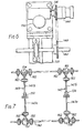
- All the reduction gear boxes are driven by a reversible electric motor 140 ( Figures 3 and 4) supported on the superstructure 133 and having an output shaft 142 above one of the two rows of anodes.
- a second shaft 143 extends above the second row of anodes in the cell.
- Transverse shafts 145 and 147 interconnect shafts 142 and 143 for transmitting drive from shaft 142 to shaft 143.
- Each of the gear boxes 143 is provided with a slipping frictional clutch 144 having its output member connected to input shaft 136 of the gear box.
- the clutches 44 associated with the anodes of the row beneath shaft 142 are all driven by shaft 142, through sprocket and chain mechanisms 148 transmitting drive from shaft 142 to the input members of the clutches 144.
- the clutches 144 associated with the anodes of the row beneath shaft 143 are driven in like manner by the shaft 143 through sprocket and chain mechanisms 148 transmitting drive to their input members from the latter shaft.
- Each gear box 132 together with its associates clutch 144 and sprocket and chain mechanism 148 is enclosed within a housing 149 supported on the superstructure 133, only a few of such housings being shown in the drawings, for the sake of simplicity of illustration; the shafts 142 and 143 extend through these housings.
- each of the slipping frictional clutches is a pneumatically operated cone clutch of a currently commercially available type, having the air cylinder built into the clutch.
- the structure and operation of such clutches are well known and accordingly need not be described in detail.
- the clutch is arranged to be disengaged by an internal spring and engaged by compressed air, when a solenoid valve is unenergized and becoming disengaged when the air is cut off by energization of the valve solenoid.
- the maximum allowable torque on the clutches is set by adjusting an air pressure regulator mounted in the clutch air supply line.
- friction clutches could be employed in place of the described pneumatic clutches 144.
- magnetic or solenoid- operated friction clutches could be used, or jaw clutches in series with wrench-adjusted torque limiter clutches or hydraulically operated clutches.
- the commercially available pneumatic clutches described above are preferred, because they are compact, easy to operate and to adjust for torque level, and capable of tolerating the conditions to which they are exposed in use on an alumina reduction cell, viz. alumina dust, high temperatures, and saturated magnetic fields.
- the solenoid valves, which operate the pneumatic clutches can conveniently be mounted in clusters on the cell superstructure.
- the system of Figures 3 to 7 can be operated in the manner already described with reference to Figures 1 and 2, to move all the anodes simultaneously in the same direction, or to move one or only some of the anodes.
- the system of Figures 3 to 7 is selectively operable to raise the anodes of one row while simultaneously lowering the anodes of the other row in such a way that the anodes all move exactly equal amounts from the equilibrium position at equal speeds because all of the anodes are mechanically linked together and driven by the one motor 140, thereby to "pump" the cell, i.e. to agitate the electrolyte to quench anode effects.
- the electrolyte level does not significantly change under these conditions so long as the number of anodes raised equals the number of anodes lowered.
- the transverse shaft 145 comprises two shaft portions 145a and 145b ( Figure 7) connected endwise through a clutch 150 intermediate the shafts 142 and 143.
- Shaft portion 145a is driven by the shaft 142 through a bevel gear box 152; while the shaft portion 145b drives shaft 143 through another bevel gear box 154.
- the transverse shaft 147 comprises shaft portions 147a and 147b connected endwise through a clutch 156, with shaft portion 147a driven by shaft 142 through a bevel gear box 158 and shaft portion 147b driving shaft 143 through a further bevel gear box 160.
- the shafts 142, 145, 147 and 143 may incorporate flexible couplings 162.
- Each of the clutches 150 and 156 is individually engageable and disengageable.
- gears in gear boxes 152 and 154 are arranged so that when clutch 150 is engaged shafts 142 and 143 turn equally in opposite directions. In the system of Figures 3 to 7, equal but opposite rotation of the shafts 142 and 143 results in all of the anodes either rising together or descending together.
- Figure 8 illustrates an alternative embodiment of the invention.
- the system of Figure 8 includes an individual jack screw (not shown) for each anode and an individual worm reduction gear box 232 for each jack directly above the anode with which it is associated.
- the arrangement of worm reduction gear boxes, screw jacks, and anodes may be essentially identical to that described above with reference to Figures 3 to 7.
- All the reduction gear boxes 232 are driven by a reversible motor 240 having an output shaft 242 lengthwise of the cell between the two rows of anodes.
- the motor 240 is at one end of the cell, and is connected to one end of the shaft 242, which extends halfway along the length of the cell.
- An aligned shaft 243 on the same centre line as shaft 242 extends to the other end of the cell; above the middle of the cell, the facing ends of shafts 242 and 243 are interconnected by a reversing gear assembly 245 for transmitting drive from the first shaft 242 to the second shaft 243.
- the two shafts 242 and 243 can be considered as a single shaft transmitting drive from the motor 240 to the worm reduction gear boxes of all the anodes of both rows.
- Each of the gear boxes 232 is provided with a disengageable slipping frictional clutch 244 (for example, of the type described above with reference to Figures 3 to 7) for driving the input shaft of the gear box.
- the clutches 244 associated with both rows of anodes in that half of the cell over which the shaft 242 extends are driven by the shaft 242 through gear assemblies 248 which transmits drive to the input members of the clutches 244, while the clutches 244 associated with the anodes of both rows in the other half of the cell are similarly driven by the shaft 243 through identical gear boxes 248 transmitting drive to their input members.
- the anodes of the two rows in the cell are paired, i.e. disposed directly opposite each other; hence from each gear box 248 a pair of opposed shafts 248a extend, at right angles to the shaft 242 or 243, toward the sides of the cell to impart drive, respectively, to the input members of two clutches 244.
- each gear box 248 is shown as comprising an assembly of bevel gears so arranged that the two shafts 248a projecting from a given gear box 248 are driven in opposite directions; in this case, the worms of the reduction gear boxes 232 associated with one row of anodes have right-handed threads while the worms of the reduction gear boxes associated with the other rows of anodes have left-handed threads, so that the anodes of both rows will move in the same direction notwithstanding the opposite directions of rotation of the shafts 248a on the two sides of the cell.
- the gear boxes 248 may alternatively be worm reduction gear boxes wherein the worm shaft is in line with and part of the shaft 242 or 243; or they may be gear boxes each having two 45° helical gears 248b and 248c which mesh at 90° to each other.
- the clutches associated with the anodes of one row driven by the shaft 243 are disengaged, as are the clutches associated with the other rows of anodes and driven by shaft 242.
- Oppositely directed drive of the shafts 242 and 243 moves the anodes on one side at one end of the cell up and simultaneously moves the anodes on the other side at the other end of the cell down by an equal amount.
Landscapes
- Chemical & Material Sciences (AREA)
- Engineering & Computer Science (AREA)
- Chemical Kinetics & Catalysis (AREA)
- Electrochemistry (AREA)
- Materials Engineering (AREA)
- Metallurgy (AREA)
- Organic Chemistry (AREA)
- Electrolytic Production Of Metals (AREA)
- Electrolytic Production Of Non-Metals, Compounds, Apparatuses Therefor (AREA)
- Die Bonding (AREA)
- Radiation-Therapy Devices (AREA)
- Vehicle Body Suspensions (AREA)
Claims (6)
Applications Claiming Priority (2)
| Application Number | Priority Date | Filing Date | Title |
|---|---|---|---|
| US06/348,170 US4414070A (en) | 1982-02-12 | 1982-02-12 | Anode positioning system |
| US348170 | 1982-02-12 |
Publications (2)
| Publication Number | Publication Date |
|---|---|
| EP0086593A1 EP0086593A1 (de) | 1983-08-24 |
| EP0086593B1 true EP0086593B1 (de) | 1986-06-18 |
Family
ID=23366902
Family Applications (1)
| Application Number | Title | Priority Date | Filing Date |
|---|---|---|---|
| EP83300523A Expired EP0086593B1 (de) | 1982-02-12 | 1983-02-02 | Anodeneinstellungsvorrichtung |
Country Status (10)
| Country | Link |
|---|---|
| US (1) | US4414070A (de) |
| EP (1) | EP0086593B1 (de) |
| JP (1) | JPS58151485A (de) |
| AU (1) | AU563592B2 (de) |
| BR (1) | BR8300749A (de) |
| CA (1) | CA1212078A (de) |
| DE (1) | DE3364112D1 (de) |
| ES (1) | ES519731A0 (de) |
| NO (1) | NO162389B (de) |
| NZ (1) | NZ203139A (de) |
Families Citing this family (34)
| Publication number | Priority date | Publication date | Assignee | Title |
|---|---|---|---|---|
| IN158317B (de) * | 1981-12-08 | 1986-10-18 | Pechiney Aluminium | |
| GB8521128D0 (en) * | 1985-08-23 | 1985-10-02 | Alcan Int Ltd | Controlling anode movement in aluminium cell |
| US4688437A (en) * | 1986-03-07 | 1987-08-25 | Orion Research, Inc. | Electrode holder assembly |
| NO160148C (no) * | 1986-08-13 | 1989-03-15 | Norsk Hydro As | Opphengingsanordning for anodebjelker i celler for smelteelektrolytisk fremstilling av aluminium. |
| EP0353943A1 (de) * | 1988-08-04 | 1990-02-07 | Alcan International Limited | Verfahren zur Begrenzung von Anodeneffekten bei der Produktion von Aluminium |
| US5294306A (en) * | 1992-11-23 | 1994-03-15 | General Motors Corporation | Electrolytic removal of magnesium from molten aluminum |
| US5876585A (en) * | 1996-05-29 | 1999-03-02 | Schenk; Rodney J. | Anode clamp |
| US5843296A (en) * | 1996-12-26 | 1998-12-01 | Digital Matrix | Method for electroforming an optical disk stamper |
| US5785826A (en) * | 1996-12-26 | 1998-07-28 | Digital Matrix | Apparatus for electroforming |
| RU2213164C2 (ru) * | 2000-09-11 | 2003-09-27 | Открытое акционерное общество "Красноярский алюминиевый завод" | Способ автоматической стабилизации положения анодного кожуха алюминиевого электролизера и устройство для его осуществления |
| US20030042134A1 (en) * | 2001-06-22 | 2003-03-06 | The Procter & Gamble Company | High efficiency electrolysis cell for generating oxidants in solutions |
| KR100429154B1 (ko) * | 2001-06-15 | 2004-04-28 | 주식회사 포스코 | 아노드 브릿지와 단위별 아노드 갭조정장치 |
| US20040149571A1 (en) * | 2001-09-06 | 2004-08-05 | The Procter & Gamble Company | Electrolysis cell for generating halogen (and particularly chlorine) dioxide in an appliance |
| RU2214481C1 (ru) * | 2002-05-06 | 2003-10-20 | Открытое акционерное общество "Всероссийский алюминиево-магниевый институт" | Анодное устройство алюминиевого электролизера |
| RU2214482C1 (ru) * | 2002-05-06 | 2003-10-20 | Открытое акционерное общество "Всероссийский алюминиево-магниевый институт" | Анодное устройство электролизера с обожженными анодами |
| US6922886B2 (en) * | 2002-07-06 | 2005-08-02 | John L. Costley, Jr. | APT-1 (anode placement tool-model 1) |
| US20040055873A1 (en) * | 2002-09-24 | 2004-03-25 | Digital Matrix Corporation | Apparatus and method for improved electroforming |
| US6866767B2 (en) * | 2002-10-23 | 2005-03-15 | Alcan International Limited | Process for controlling anode effects during the production of aluminum |
| RU2319793C2 (ru) * | 2004-12-23 | 2008-03-20 | Владимир Кириллович Бутаков | Механизм подъема и опускания обожженных анодных блоков на электролизерах с неподвижной анодной рамой |
| KR20070112829A (ko) * | 2005-03-24 | 2007-11-27 | 비에치피 빌리튼 이노베이션 피티와이 엘티디 | 양극 지지 장치 |
| RU2294985C1 (ru) * | 2005-09-20 | 2007-03-10 | Открытое акционерное общество "Сибирский научно-исследовательский, конструкторский и проектный институт алюминиевой и электродной промышленности" (ОАО "СибВАМИ") | Анодное устройство алюминиевого электролизера с обожженными анодами |
| RU2324011C2 (ru) * | 2006-01-26 | 2008-05-10 | Владимир Кириллович Бутаков | Механизм подъема и опускания обожженных анодных блоков на электролизерах с неподвижной анодной рамой |
| RU2328553C2 (ru) * | 2006-08-22 | 2008-07-10 | Общество с ограниченной ответственностью "Русская инжиниринговая компания" | Анодное устройство электролизера с обожженными анодами |
| RU2338010C2 (ru) * | 2006-08-30 | 2008-11-10 | Общество с ограниченной ответственностью "Русская инжиниринговая компания" | Анодное устройство алюминиевого электролизера |
| CN101392391B (zh) * | 2007-09-21 | 2010-08-25 | 贵阳铝镁设计研究院 | 电解槽阳极限位脉冲计数检测方法及装置 |
| SE532197C2 (sv) * | 2007-10-15 | 2009-11-10 | Alfa Laval Corp Ab | Plattvärmeväxlare |
| RU2458186C1 (ru) * | 2011-04-01 | 2012-08-10 | Общество с ограниченной ответственностью "Объединенная Компания РУСАЛ Инженерно-технологический центр" | Анодное устройство алюминиевого электролизера |
| GB2543788A (en) * | 2015-10-28 | 2017-05-03 | Dubai Aluminium Pjsc | Superstructure for electrolytic cell, comprising means of moving anode beam with respect to the frame of this superstructure |
| FI127194B (fi) | 2016-04-14 | 2018-01-31 | Kumera Drives Oy | Menetelmä ja säätölaitemekanismi alumiinisulaton yhteydessä |
| NO20162006A1 (en) * | 2016-12-15 | 2018-06-18 | Norsk Hydro As | A suspension arrangement for anode beams in cells of Hall-Héroult type for the electrolytic production of aluminum and a method for stabilizing the operation of such cells |
| CN108486608A (zh) * | 2018-06-04 | 2018-09-04 | 山西亮宇炭素有限公司 | 一种预焙阳极铝电解槽阳极单块自由升降系统 |
| US10890384B2 (en) | 2019-02-22 | 2021-01-12 | Alfa Laval Corporate Ab | Plate heat exchanger |
| FR3093737B1 (fr) * | 2019-03-14 | 2023-02-24 | Rio Tinto Alcan Int Ltd | Dispositif de manutention destiné à convoyer un outil d’intervention sur une cuve d’électrolyse. |
| FR3093736B1 (fr) * | 2019-03-14 | 2021-02-19 | Rio Tinto Alcan Int Ltd | Outil d’intervention pour l’exploitation d’une cuve d’électrolyse |
Family Cites Families (7)
| Publication number | Priority date | Publication date | Assignee | Title |
|---|---|---|---|---|
| DE1163558B (de) * | 1960-12-23 | 1964-02-20 | Aluminium Ind Ag | Elektrolysezelle zur Herstellung von Aluminium |
| US3329592A (en) * | 1963-08-30 | 1967-07-04 | Reynolds Metals Co | Method of and apparatus for controlling aluminum reduction pots |
| US3761379A (en) * | 1971-07-20 | 1973-09-25 | C Elliott | Aluminum production apparatus |
| US4039419A (en) * | 1976-07-23 | 1977-08-02 | Aluminum Company Of America | Anode positioning device |
| US4210513A (en) * | 1978-11-02 | 1980-07-01 | Aluminum Company Of America | Pneumatic anode positioning system |
| FR2473194A1 (fr) * | 1980-01-04 | 1981-07-10 | Aluminum Co Of America | Dispositif de positionnement d'anodes dans une cellule d'electrolyse |
| US4269673A (en) * | 1980-01-28 | 1981-05-26 | Aluminum Company Of America | Anode mount |
-
1982
- 1982-02-12 US US06/348,170 patent/US4414070A/en not_active Expired - Fee Related
-
1983
- 1983-01-31 NZ NZ203139A patent/NZ203139A/en unknown
- 1983-02-02 EP EP83300523A patent/EP0086593B1/de not_active Expired
- 1983-02-02 DE DE8383300523T patent/DE3364112D1/de not_active Expired
- 1983-02-11 NO NO830467A patent/NO162389B/no unknown
- 1983-02-11 AU AU11371/83A patent/AU563592B2/en not_active Ceased
- 1983-02-11 BR BR8300749A patent/BR8300749A/pt not_active IP Right Cessation
- 1983-02-11 ES ES519731A patent/ES519731A0/es active Granted
- 1983-02-11 CA CA000421471A patent/CA1212078A/en not_active Expired
- 1983-02-12 JP JP58021980A patent/JPS58151485A/ja active Pending
Also Published As
| Publication number | Publication date |
|---|---|
| BR8300749A (pt) | 1983-11-16 |
| US4414070A (en) | 1983-11-08 |
| NZ203139A (en) | 1985-08-16 |
| ES8403167A1 (es) | 1984-03-01 |
| JPS58151485A (ja) | 1983-09-08 |
| ES519731A0 (es) | 1984-03-01 |
| DE3364112D1 (en) | 1986-07-24 |
| AU1137183A (en) | 1983-08-18 |
| AU563592B2 (en) | 1987-07-16 |
| NO830467L (no) | 1983-08-15 |
| EP0086593A1 (de) | 1983-08-24 |
| NO162389B (no) | 1989-09-11 |
| CA1212078A (en) | 1986-09-30 |
Similar Documents
| Publication | Publication Date | Title |
|---|---|---|
| EP0086593A1 (de) | Anodeneinstellungsvorrichtung | |
| US4210513A (en) | Pneumatic anode positioning system | |
| CN113964561A (zh) | 一种应用于无人机作业的输电线路新型接地线装置 | |
| EP0427013B1 (de) | Schwimmbagger | |
| SE405347B (sv) | Forfarande for lyftning av en last under anvendning av ett par kranar i tandem samt anordning herfor | |
| CN213061952U (zh) | 一种水上漂浮物柔性拦截打捞机构 | |
| US5549799A (en) | Hoist apparatus for positioning anode in smelting furnace | |
| CN117650406B (zh) | 电极接长机器人 | |
| CN117163866A (zh) | 手动电动双重控制的升降装置、方法及晶种升降设备 | |
| CN201915365U (zh) | 一种组合式螺杆式启闭机 | |
| CN217591647U (zh) | 一种可手动驱动的卷帘机 | |
| CN215556779U (zh) | 一种适用于砖块生产线的物料输送机 | |
| CN114920129A (zh) | 一种适用于悬索桥钢结构桥面的吊装系统 | |
| CN221036800U (zh) | 一种用于清理炉眼溜槽机器人 | |
| CN211517903U (zh) | 一种切割效果好的加气砖切割装置 | |
| CN116946273A (zh) | 用于带电作业的载人装置 | |
| CN214014048U (zh) | 一种高速电机行星减速器 | |
| CN220862643U (zh) | 一种螺栓冷镦成型用定位装置 | |
| CN217416146U (zh) | 一种挂点模拟装置专用智能测控设备 | |
| US3778345A (en) | Device for engaging and disengaging pinion and rack in drive of nuclear reactor regulating element | |
| CN218949404U (zh) | 一种抛锚固定机构 | |
| CN217992295U (zh) | 柔性夹具 | |
| CN221459720U (zh) | 一种纯化炉重载零件提升装置 | |
| CN221565556U (zh) | 一种矿产开发用吊装装置 | |
| CN212863901U (zh) | 一种电厂锅炉维修用起吊架 |
Legal Events
| Date | Code | Title | Description |
|---|---|---|---|
| PUAI | Public reference made under article 153(3) epc to a published international application that has entered the european phase |
Free format text: ORIGINAL CODE: 0009012 |
|
| AK | Designated contracting states |
Designated state(s): CH DE FR GB LI NL |
|
| RAP1 | Party data changed (applicant data changed or rights of an application transferred) |
Owner name: ALCAN INTERNATIONAL LIMITED |
|
| 17P | Request for examination filed |
Effective date: 19840220 |
|
| RAP1 | Party data changed (applicant data changed or rights of an application transferred) |
Owner name: ALCAN INTERNATIONAL LIMITED |
|
| GRAA | (expected) grant |
Free format text: ORIGINAL CODE: 0009210 |
|
| AK | Designated contracting states |
Kind code of ref document: B1 Designated state(s): CH DE FR GB LI NL |
|
| PG25 | Lapsed in a contracting state [announced via postgrant information from national office to epo] |
Ref country code: NL Effective date: 19860618 Ref country code: LI Effective date: 19860618 Ref country code: CH Effective date: 19860618 |
|
| REF | Corresponds to: |
Ref document number: 3364112 Country of ref document: DE Date of ref document: 19860724 |
|
| ET | Fr: translation filed | ||
| REG | Reference to a national code |
Ref country code: CH Ref legal event code: PL |
|
| NLV1 | Nl: lapsed or annulled due to failure to fulfill the requirements of art. 29p and 29m of the patents act | ||
| PLBE | No opposition filed within time limit |
Free format text: ORIGINAL CODE: 0009261 |
|
| STAA | Information on the status of an ep patent application or granted ep patent |
Free format text: STATUS: NO OPPOSITION FILED WITHIN TIME LIMIT |
|
| 26N | No opposition filed | ||
| GBPC | Gb: european patent ceased through non-payment of renewal fee | ||
| PG25 | Lapsed in a contracting state [announced via postgrant information from national office to epo] |
Ref country code: GB Effective date: 19881122 |
|
| PGFP | Annual fee paid to national office [announced via postgrant information from national office to epo] |
Ref country code: FR Payment date: 19920109 Year of fee payment: 10 |
|
| PGFP | Annual fee paid to national office [announced via postgrant information from national office to epo] |
Ref country code: DE Payment date: 19920114 Year of fee payment: 10 |
|
| PG25 | Lapsed in a contracting state [announced via postgrant information from national office to epo] |
Ref country code: FR Effective date: 19931029 |
|
| PG25 | Lapsed in a contracting state [announced via postgrant information from national office to epo] |
Ref country code: DE Effective date: 19931103 |
|
| REG | Reference to a national code |
Ref country code: FR Ref legal event code: ST |