EP0086028B1 - Water purifying method and system - Google Patents
Water purifying method and system Download PDFInfo
- Publication number
- EP0086028B1 EP0086028B1 EP83300024A EP83300024A EP0086028B1 EP 0086028 B1 EP0086028 B1 EP 0086028B1 EP 83300024 A EP83300024 A EP 83300024A EP 83300024 A EP83300024 A EP 83300024A EP 0086028 B1 EP0086028 B1 EP 0086028B1
- Authority
- EP
- European Patent Office
- Prior art keywords
- water
- membrane
- housing
- hollow fiber
- pore diameter
- Prior art date
- Legal status (The legal status is an assumption and is not a legal conclusion. Google has not performed a legal analysis and makes no representation as to the accuracy of the status listed.)
- Expired
Links
- XLYOFNOQVPJJNP-UHFFFAOYSA-N water Substances O XLYOFNOQVPJJNP-UHFFFAOYSA-N 0.000 title claims description 137
- 238000000034 method Methods 0.000 title claims description 36
- 239000012528 membrane Substances 0.000 claims description 98
- 239000011148 porous material Substances 0.000 claims description 48
- 238000001914 filtration Methods 0.000 claims description 45
- 239000012510 hollow fiber Substances 0.000 claims description 45
- 239000002510 pyrogen Substances 0.000 claims description 37
- -1 polyethylene Polymers 0.000 claims description 20
- 150000002894 organic compounds Chemical class 0.000 claims description 16
- 241000894006 Bacteria Species 0.000 claims description 15
- 239000008399 tap water Substances 0.000 claims description 15
- 235000020679 tap water Nutrition 0.000 claims description 15
- 239000000463 material Substances 0.000 claims description 14
- 239000004698 Polyethylene Substances 0.000 claims description 12
- 229920000573 polyethylene Polymers 0.000 claims description 12
- 229920000098 polyolefin Polymers 0.000 claims description 12
- 239000002349 well water Substances 0.000 claims description 8
- 235000020681 well water Nutrition 0.000 claims description 8
- QSHDDOUJBYECFT-UHFFFAOYSA-N mercury Chemical compound [Hg] QSHDDOUJBYECFT-UHFFFAOYSA-N 0.000 claims description 7
- 229910052753 mercury Inorganic materials 0.000 claims description 7
- 210000001724 microfibril Anatomy 0.000 claims description 7
- 239000004743 Polypropylene Substances 0.000 claims description 6
- 229920001155 polypropylene Polymers 0.000 claims description 6
- 239000000835 fiber Substances 0.000 claims description 5
- 238000013022 venting Methods 0.000 claims description 5
- 229920005989 resin Polymers 0.000 claims description 4
- 239000011347 resin Substances 0.000 claims description 4
- 239000000645 desinfectant Substances 0.000 claims description 2
- 239000012982 microporous membrane Substances 0.000 claims description 2
- 238000011109 contamination Methods 0.000 claims 1
- 238000012360 testing method Methods 0.000 description 15
- 230000035699 permeability Effects 0.000 description 14
- 239000000126 substance Substances 0.000 description 14
- LFQSCWFLJHTTHZ-UHFFFAOYSA-N Ethanol Chemical compound CCO LFQSCWFLJHTTHZ-UHFFFAOYSA-N 0.000 description 13
- DOIRQSBPFJWKBE-UHFFFAOYSA-N dibutyl phthalate Chemical compound CCCCOC(=O)C1=CC=CC=C1C(=O)OCCCC DOIRQSBPFJWKBE-UHFFFAOYSA-N 0.000 description 12
- 235000019441 ethanol Nutrition 0.000 description 7
- 230000008569 process Effects 0.000 description 6
- 230000007423 decrease Effects 0.000 description 5
- 241000239218 Limulus Species 0.000 description 4
- 239000003708 ampul Substances 0.000 description 4
- 230000002349 favourable effect Effects 0.000 description 4
- 238000012454 limulus amebocyte lysate test Methods 0.000 description 4
- 239000002245 particle Substances 0.000 description 4
- 238000000746 purification Methods 0.000 description 4
- 244000052616 bacterial pathogen Species 0.000 description 3
- 210000004369 blood Anatomy 0.000 description 3
- 239000008280 blood Substances 0.000 description 3
- 210000000601 blood cell Anatomy 0.000 description 3
- 238000007599 discharging Methods 0.000 description 3
- 229920003023 plastic Polymers 0.000 description 3
- 239000004033 plastic Substances 0.000 description 3
- 229920005749 polyurethane resin Polymers 0.000 description 3
- 238000002360 preparation method Methods 0.000 description 3
- 230000001698 pyrogenic effect Effects 0.000 description 3
- ZCYVEMRRCGMTRW-UHFFFAOYSA-N 7553-56-2 Chemical compound [I] ZCYVEMRRCGMTRW-UHFFFAOYSA-N 0.000 description 2
- IJGRMHOSHXDMSA-UHFFFAOYSA-N Atomic nitrogen Chemical compound N#N IJGRMHOSHXDMSA-UHFFFAOYSA-N 0.000 description 2
- 230000008952 bacterial invasion Effects 0.000 description 2
- 230000008859 change Effects 0.000 description 2
- 238000006243 chemical reaction Methods 0.000 description 2
- 239000003153 chemical reaction reagent Substances 0.000 description 2
- 230000000052 comparative effect Effects 0.000 description 2
- 150000001875 compounds Chemical class 0.000 description 2
- 239000000356 contaminant Substances 0.000 description 2
- 238000001514 detection method Methods 0.000 description 2
- 238000004821 distillation Methods 0.000 description 2
- 239000012153 distilled water Substances 0.000 description 2
- 239000003814 drug Substances 0.000 description 2
- 229940079593 drug Drugs 0.000 description 2
- 239000000194 fatty acid Substances 0.000 description 2
- 235000020680 filtered tap water Nutrition 0.000 description 2
- 238000001879 gelation Methods 0.000 description 2
- 239000012535 impurity Substances 0.000 description 2
- 238000002347 injection Methods 0.000 description 2
- 239000007924 injection Substances 0.000 description 2
- 229910052740 iodine Inorganic materials 0.000 description 2
- 239000011630 iodine Substances 0.000 description 2
- 239000007788 liquid Substances 0.000 description 2
- 230000007246 mechanism Effects 0.000 description 2
- 239000002207 metabolite Substances 0.000 description 2
- 239000005416 organic matter Substances 0.000 description 2
- 238000001223 reverse osmosis Methods 0.000 description 2
- 150000003384 small molecules Chemical class 0.000 description 2
- 239000000243 solution Substances 0.000 description 2
- 238000001179 sorption measurement Methods 0.000 description 2
- MQIUGAXCHLFZKX-UHFFFAOYSA-N Di-n-octyl phthalate Natural products CCCCCCCCOC(=O)C1=CC=CC=C1C(=O)OCCCCCCCC MQIUGAXCHLFZKX-UHFFFAOYSA-N 0.000 description 1
- 241000233866 Fungi Species 0.000 description 1
- 229930186217 Glycolipid Natural products 0.000 description 1
- 206010037660 Pyrexia Diseases 0.000 description 1
- 229920000297 Rayon Polymers 0.000 description 1
- 240000004808 Saccharomyces cerevisiae Species 0.000 description 1
- 239000002253 acid Substances 0.000 description 1
- 230000001580 bacterial effect Effects 0.000 description 1
- 150000001555 benzenes Chemical class 0.000 description 1
- BJQHLKABXJIVAM-UHFFFAOYSA-N bis(2-ethylhexyl) phthalate Chemical compound CCCCC(CC)COC(=O)C1=CC=CC=C1C(=O)OCC(CC)CCCC BJQHLKABXJIVAM-UHFFFAOYSA-N 0.000 description 1
- ZFMQKOWCDKKBIF-UHFFFAOYSA-N bis(3,5-difluorophenyl)phosphane Chemical compound FC1=CC(F)=CC(PC=2C=C(F)C=C(F)C=2)=C1 ZFMQKOWCDKKBIF-UHFFFAOYSA-N 0.000 description 1
- 238000004587 chromatography analysis Methods 0.000 description 1
- 238000007796 conventional method Methods 0.000 description 1
- 238000011161 development Methods 0.000 description 1
- 235000014113 dietary fatty acids Nutrition 0.000 description 1
- 230000003292 diminished effect Effects 0.000 description 1
- MIMDHDXOBDPUQW-UHFFFAOYSA-N dioctyl decanedioate Chemical compound CCCCCCCCOC(=O)CCCCCCCCC(=O)OCCCCCCCC MIMDHDXOBDPUQW-UHFFFAOYSA-N 0.000 description 1
- XWVQUJDBOICHGH-UHFFFAOYSA-N dioctyl nonanedioate Chemical compound CCCCCCCCOC(=O)CCCCCCCC(=O)OCCCCCCCC XWVQUJDBOICHGH-UHFFFAOYSA-N 0.000 description 1
- 235000020188 drinking water Nutrition 0.000 description 1
- 239000003651 drinking water Substances 0.000 description 1
- 230000000694 effects Effects 0.000 description 1
- 150000002148 esters Chemical class 0.000 description 1
- 125000005909 ethyl alcohol group Chemical group 0.000 description 1
- 238000001704 evaporation Methods 0.000 description 1
- 238000002474 experimental method Methods 0.000 description 1
- 229930195729 fatty acid Natural products 0.000 description 1
- 239000000706 filtrate Substances 0.000 description 1
- 235000013305 food Nutrition 0.000 description 1
- BHEPBYXIRTUNPN-UHFFFAOYSA-N hydridophosphorus(.) (triplet) Chemical compound [PH] BHEPBYXIRTUNPN-UHFFFAOYSA-N 0.000 description 1
- XMBWDFGMSWQBCA-UHFFFAOYSA-N hydrogen iodide Chemical compound I XMBWDFGMSWQBCA-UHFFFAOYSA-N 0.000 description 1
- 229920001600 hydrophobic polymer Polymers 0.000 description 1
- 238000011534 incubation Methods 0.000 description 1
- 238000009776 industrial production Methods 0.000 description 1
- 239000003978 infusion fluid Substances 0.000 description 1
- 239000004615 ingredient Substances 0.000 description 1
- 238000003475 lamination Methods 0.000 description 1
- 230000007774 longterm Effects 0.000 description 1
- 210000002751 lymph Anatomy 0.000 description 1
- 239000006166 lysate Substances 0.000 description 1
- 238000004519 manufacturing process Methods 0.000 description 1
- 238000002074 melt spinning Methods 0.000 description 1
- 229910052757 nitrogen Inorganic materials 0.000 description 1
- XNGIFLGASWRNHJ-UHFFFAOYSA-N phthalic acid Chemical class OC(=O)C1=CC=CC=C1C(O)=O XNGIFLGASWRNHJ-UHFFFAOYSA-N 0.000 description 1
- 239000004417 polycarbonate Substances 0.000 description 1
- 229920000515 polycarbonate Polymers 0.000 description 1
- 229920005668 polycarbonate resin Polymers 0.000 description 1
- 239000004431 polycarbonate resin Substances 0.000 description 1
- 229920000642 polymer Polymers 0.000 description 1
- 229920002635 polyurethane Polymers 0.000 description 1
- 239000004814 polyurethane Substances 0.000 description 1
- 239000004800 polyvinyl chloride Substances 0.000 description 1
- 229920000915 polyvinyl chloride Polymers 0.000 description 1
- 238000012545 processing Methods 0.000 description 1
- 238000005086 pumping Methods 0.000 description 1
- 239000008213 purified water Substances 0.000 description 1
- 238000004451 qualitative analysis Methods 0.000 description 1
- 238000004445 quantitative analysis Methods 0.000 description 1
- 230000009467 reduction Effects 0.000 description 1
- 230000000717 retained effect Effects 0.000 description 1
- 230000035939 shock Effects 0.000 description 1
- 230000001954 sterilising effect Effects 0.000 description 1
- 238000004659 sterilization and disinfection Methods 0.000 description 1
- 238000001356 surgical procedure Methods 0.000 description 1
- 230000002195 synergetic effect Effects 0.000 description 1
- 239000012085 test solution Substances 0.000 description 1
- 238000000108 ultra-filtration Methods 0.000 description 1
- 238000005406 washing Methods 0.000 description 1
Images

Classifications
-
- C—CHEMISTRY; METALLURGY
- C02—TREATMENT OF WATER, WASTE WATER, SEWAGE, OR SLUDGE
- C02F—TREATMENT OF WATER, WASTE WATER, SEWAGE, OR SLUDGE
- C02F1/00—Treatment of water, waste water, or sewage
- C02F1/02—Treatment of water, waste water, or sewage by heating
- C02F1/04—Treatment of water, waste water, or sewage by heating by distillation or evaporation
- C02F1/08—Thin film evaporation
-
- C—CHEMISTRY; METALLURGY
- C02—TREATMENT OF WATER, WASTE WATER, SEWAGE, OR SLUDGE
- C02F—TREATMENT OF WATER, WASTE WATER, SEWAGE, OR SLUDGE
- C02F1/00—Treatment of water, waste water, or sewage
- C02F1/44—Treatment of water, waste water, or sewage by dialysis, osmosis or reverse osmosis
- C02F1/444—Treatment of water, waste water, or sewage by dialysis, osmosis or reverse osmosis by ultrafiltration or microfiltration
-
- A—HUMAN NECESSITIES
- A61—MEDICAL OR VETERINARY SCIENCE; HYGIENE
- A61L—METHODS OR APPARATUS FOR STERILISING MATERIALS OR OBJECTS IN GENERAL; DISINFECTION, STERILISATION OR DEODORISATION OF AIR; CHEMICAL ASPECTS OF BANDAGES, DRESSINGS, ABSORBENT PADS OR SURGICAL ARTICLES; MATERIALS FOR BANDAGES, DRESSINGS, ABSORBENT PADS OR SURGICAL ARTICLES
- A61L2/00—Methods or apparatus for disinfecting or sterilising materials or objects other than foodstuffs or contact lenses; Accessories therefor
- A61L2/02—Methods or apparatus for disinfecting or sterilising materials or objects other than foodstuffs or contact lenses; Accessories therefor using physical phenomena
- A61L2/022—Filtration
-
- B—PERFORMING OPERATIONS; TRANSPORTING
- B01—PHYSICAL OR CHEMICAL PROCESSES OR APPARATUS IN GENERAL
- B01D—SEPARATION
- B01D61/00—Processes of separation using semi-permeable membranes, e.g. dialysis, osmosis or ultrafiltration; Apparatus, accessories or auxiliary operations specially adapted therefor
- B01D61/14—Ultrafiltration; Microfiltration
- B01D61/145—Ultrafiltration
- B01D61/146—Ultrafiltration comprising multiple ultrafiltration steps
-
- B—PERFORMING OPERATIONS; TRANSPORTING
- B01—PHYSICAL OR CHEMICAL PROCESSES OR APPARATUS IN GENERAL
- B01D—SEPARATION
- B01D61/00—Processes of separation using semi-permeable membranes, e.g. dialysis, osmosis or ultrafiltration; Apparatus, accessories or auxiliary operations specially adapted therefor
- B01D61/14—Ultrafiltration; Microfiltration
- B01D61/147—Microfiltration
-
- B—PERFORMING OPERATIONS; TRANSPORTING
- B01—PHYSICAL OR CHEMICAL PROCESSES OR APPARATUS IN GENERAL
- B01D—SEPARATION
- B01D61/00—Processes of separation using semi-permeable membranes, e.g. dialysis, osmosis or ultrafiltration; Apparatus, accessories or auxiliary operations specially adapted therefor
- B01D61/14—Ultrafiltration; Microfiltration
- B01D61/20—Accessories; Auxiliary operations
-
- B—PERFORMING OPERATIONS; TRANSPORTING
- B01—PHYSICAL OR CHEMICAL PROCESSES OR APPARATUS IN GENERAL
- B01D—SEPARATION
- B01D63/00—Apparatus in general for separation processes using semi-permeable membranes
- B01D63/02—Hollow fibre modules
- B01D63/024—Hollow fibre modules with a single potted end
- B01D63/0241—Hollow fibre modules with a single potted end being U-shaped
-
- B—PERFORMING OPERATIONS; TRANSPORTING
- B01—PHYSICAL OR CHEMICAL PROCESSES OR APPARATUS IN GENERAL
- B01D—SEPARATION
- B01D63/00—Apparatus in general for separation processes using semi-permeable membranes
- B01D63/02—Hollow fibre modules
- B01D63/04—Hollow fibre modules comprising multiple hollow fibre assemblies
- B01D63/046—Hollow fibre modules comprising multiple hollow fibre assemblies in separate housings
-
- B—PERFORMING OPERATIONS; TRANSPORTING
- B01—PHYSICAL OR CHEMICAL PROCESSES OR APPARATUS IN GENERAL
- B01D—SEPARATION
- B01D69/00—Semi-permeable membranes for separation processes or apparatus characterised by their form, structure or properties; Manufacturing processes specially adapted therefor
- B01D69/02—Semi-permeable membranes for separation processes or apparatus characterised by their form, structure or properties; Manufacturing processes specially adapted therefor characterised by their properties
-
- B—PERFORMING OPERATIONS; TRANSPORTING
- B01—PHYSICAL OR CHEMICAL PROCESSES OR APPARATUS IN GENERAL
- B01D—SEPARATION
- B01D69/00—Semi-permeable membranes for separation processes or apparatus characterised by their form, structure or properties; Manufacturing processes specially adapted therefor
- B01D69/08—Hollow fibre membranes
-
- B—PERFORMING OPERATIONS; TRANSPORTING
- B01—PHYSICAL OR CHEMICAL PROCESSES OR APPARATUS IN GENERAL
- B01D—SEPARATION
- B01D71/00—Semi-permeable membranes for separation processes or apparatus characterised by the material; Manufacturing processes specially adapted therefor
- B01D71/06—Organic material
- B01D71/26—Polyalkenes
- B01D71/261—Polyethylene
-
- B—PERFORMING OPERATIONS; TRANSPORTING
- B01—PHYSICAL OR CHEMICAL PROCESSES OR APPARATUS IN GENERAL
- B01D—SEPARATION
- B01D71/00—Semi-permeable membranes for separation processes or apparatus characterised by the material; Manufacturing processes specially adapted therefor
- B01D71/06—Organic material
- B01D71/26—Polyalkenes
- B01D71/262—Polypropylene
Definitions
- the present invention relates to a method of purifying water and to a water purification system. More particularly, the invention relates to a method and system for the purification of water for a variety of applications including the preparation of drugs, as drinking water, and for use in administering medical care and in the food industry, in the precious electronic industry and for physical and chemical experiments.
- Pyrogen is a generic name for pyrogenic substances such as the metabolites of bacteria, fungi and yeast, which are defined as substances which induce exothermal reactions in an organism upon injection. Chemically, pyrogens are said to be heat-resistant, high molecular weight complex glycolipids containing nitrogen and phosphorous, and are of a particle size of 1-5 nm and are water-soluble. Pyrogens in micro-amounts of about 0.01 pg/kg are reported to induce pyrogenic reactions in an organism. Pyrogens entering an organism such as by injection into the blood, by infusion-solution, drugs, and the like will cause such side effects as fever or shock. Accordingly, the water which is used for medical care should be germless and pyrogen free.
- pyrogens cannot be removed from water or be destroyed by the bacteria-filtering method or the high-pressure steam-sterilising method.
- specialized water-treating methods must be used to obtain pyrogen-free water.
- a "small amount” means amounts in the ranges of parts per billion (p.p.b.) and parts per trillion (p.p.t.).
- phthalate esters dibutyl phthalate, dioctyl phthalate, and the like
- straight-chain dibasic acid esters dioctyl adipate, dioctyl azelate, dioctyl sebacate, and the like
- other higher fatty acid esters higher-fatty acids
- other halogenated benzenes which are present in water in amounts of from several p.p.t. to hundreds p.p.t.
- one object of the present invention is to provide a method and system by which organic compounds and other contaminants present in water in trace amounts can be efficiently and effectively removed.
- EP-A-50,399 (Mitsubishi Rayon Co. Ltd.) forms part of the state of the art against the present application by virtue of Article 54(3)EPC. It discloses a method of separating plasma from blood involving the use of a microporous polyolefin membrane having rectangularly shaped nodule areas, each nodule area containing a plurality of strip-like microfibrils arranged in a longitudinal direction.
- EP-A-50,399 also discloses a single-stage filtering apparatus using such membranes.
- the invention provides a water purifying method capable of removing small amounts of bacteria, pyrogens and low molecular weight organic compounds from contaminated water, comprising:
- the invention provides a multi-stage water filtering apparatus (Fig. 3, Fig. 4), comprising:
- the shape of the porous polyolefin membrane used in the present invention may be either a flat film or a tubular membrane.
- a porous hollow fiber membrane which is a structure having a larger membrane surface area per unit volume, is a particularly favorable structure.
- porous hollow fibers having the special microstructure mentioned above can be manufactured by proper control of the processing conditions in the hot stretching step after the cold stretching of highly oriented untreated crystalline hollow fibers obtained by melt-spinning of a polymer, e.g., polypropylene or polyethylene, through a special nozzle for manufacturing the hollow fiber.
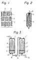
- Figure 1 is a schematic drawing of the stacking structure of strip-like micropores.
- (1) denotes microfibrils
- (2) denotes a multitude of rectangularly shaped modular portions containing the microfibrils (1)
- (3) denotes strip-like micropores
- the micropores (3) which are composed of microfibrils and nodular portions, form the stacking structure through each nodular portion.
- the stacking structure of the micropore shows the lamination in the fiber-length direction within one plane through the nodular portion, and simultaneously, it means that the plane having such a structure is piled in the thickness-direction of the wall of the hollow fiber.
- Such a special micro-structured membrane is a key element in the present process which contributes to the purification of water.
- the mean pore diameter of the micropores measured by a mercury porosimeter be 0.03-0.8 ⁇ m.
- Micropores of a size less than 0.03 ⁇ are not favorable from the viewpoint of a marked reduction of water-permeability which results in diminished filtering efficiency.
- Micropore diameters over 0.8 pm are unfavorable because of the reduced trend to efficaciously remove low molecular weight compounds present in water in small amounts as mentioned before, although bacterial removal is possible.
- pore size and membrane material is such that even when the mean pore diameter of the micropore membrane is within the range of 0.03-0.8 ⁇ m, microporous membrane materials other than porous polyolefin membranes are unsatisfactory because of the marked lowering of the rate of removal of the said organic compounds mentioned above. That is, both the microporous structure of the present membrane and the material of the membrane itself which is a polyolefin, are important factors which contribute to the removal of the said organic compound from water by the synergic action of filtering and adsorption.
- the membrane its greater water-permeability is an important factor in its practicality and it is desirable that the initial filtering flow rate when filtering distilled water through the membranes should be over 1 liter/min/m 2 with a hyraulic pressure of 1 kg/cm 2 (98.1 kPa) under normal temperatures. At flow rates less than 1 Iiter/min/m 2 the membrane shows less water-permeability with less intake of purifying water per unit hour; thus it is not practical.
- The; membrane of the present invention has the feature of a micro-stacking structure with strip-like pores, and in spite of the fact that the mean pore diameter of the micropores is as small as 0.03-0.8 ⁇ m, the membrane has a very substantial water-permeability.
- the efficacy of the membrane becomes much greater by the use of a porous hollow fiber having a porosity of 20-90 vol % as mentioned later.
- the wall thickness of the porous hollow fiber desirably should be 10-100 ⁇ m for stable industrial production, while a thickness less than 10 ⁇ m is mechanically weak which presents problems. There is no necessity for the membrane to be over 100 ⁇ m thick. A thickness of 20-80 ⁇ m is especially desirable.
- the proper range for porosity of the membrane as measured by a mercury porosimeter is 20-90 vol %.
- the porosity should not be less than 20 vol % because the permeability of water decreases, while the porosity should not be over 90 vol % because the membrane will be weaker mechanically.
- a value of 40-80 vol % is especially desirable.
- the membrane should actually be the microporous polyolefin hollow fiber
- the wall thickness T (pm) of the fiber should be 10-100 ⁇ m
- the porosity of the membrane as measured by a mercury porosimeter should be 20-90 vol %
- the mean pore diameter D (pm) of the micropores should be less than 0.03 p and D should be less than 0.002 x T + 0.3.
- a larger pore diameter of the micropores and a larger porosity of the membrane both favor pyrogen removal because of larger permeability of the membrane.
- the upper limit of the pore diameter for filtering pyrogens has proved to change by the membrane thickness T (11m) of the hollow fiber membrane. That is, a larger membrane thickness (T) results in absence of pyrogens in the filtrate even when the membrane possessed a larger mean pore diameter.
- the membrane thickness of the hollow fiber be 10-100 11m, with a preferred range being 20-80 pm.
- the porosity is desirably 20-90 vol% with a preferred favorable range being 40-90 vol% in view of the balance of physical strength of the membrane and water-permeability.
- the water-purifying technique of the present invention in an embodiment in which water if filtered through membranes in a plurality of stages, is satisfactory.
- the reliability of this embodiment can be improved for the removal of the above-mentioned substances by two or more stages of filtration, and also, by balancing the area and pore diameter of the membranes between the initial and subsequent stages, a far longer service-life can be obtained than can be obtained in a single stage process.
- a desirable relation is S n ⁇ S n+1 , where S n is the surface area of the membrane at the nth stage.
- the multi-stage filtering method of the present invention is especially preferred as a means of preventing the occurrence of the above phenomenon because of the remarkable decrease in water permeability observed, especially in the case of tap water containing over 200 p.p.b. of the organic compounds.
- the mean pore diameter of the film in the initial stage is desirably larger than the mean pore diameters of subsequent stages, and yet, even when the mean pore diameter is the same for the membranes between the initial and subsequent stages, it is possible to prevent water permeability decreases.
- the filtering resistance of the film at the initial stage becomes rate determining and the water permeability is reduced, which result is unfavorable.
- the type of water which is treated is well-water or tap water having relatively few impurities, since it is intended to remove bacteria, pyrogens, and low molecular weight organic compounds all present in small amounts in water by a higher-order treatment. Accordingly, if highly contaminated water is to be treated by the present process, it should be pretreated.
- the present invention is intended for the continuous treatment of water immediately before use. Moreover, without using pressurizing means such as pumps, or the like, it is possible to obtain treated water by operating the system with hydraulic pressure alone at the water source by mounting the system of the present invention on the city water tap or at the well-water pipe of the pumping system. For example, such methods as distillation and reverse osmosis can be used as effective means for removing bacteria and pyrogens from water.
- the treated water must be stored in a tank for future use, whereby, in many cases, bacteria in the air may enter into the water through pipes or pipe connections. Thus, the treated water becomes contaminated and the water will contain pyrogens as metabolites of bacteria. In order to prevent this situation the present invention has been developed and germfree and pyrogen free water can be obtained with high reliability by the method of the present invention without having to store the treated water just before use.
- the apparatus of the invention enables bacteria, pyrogens and low molecular weight organic compounds present in small amounts to be removed from water with greater reliability than previously obtainable.
- the present invention is particularly useful in a water-purifying system as shown in Figure 2 wherein the filtering material is made of a microporous hollow fiber bundle bent into a U shape (4) and bound at the tip with a resin (5) while keeping the open ends (6) of the hollow fibers open at the outlet (6) of the housing.
- the system is provided with a water inlet.
- the water is treated by permeation through the microporous hollow fiber membrane.
- the water-permeating direction is shown from the outside to the inside of the hollow fiber, but a flow of water in the opposite direction is also satisfactory.
- FIG 3 shows an example of assembled modules in multiple stages, with the system being provided with a shower nozzle (10) which prevents bacterial invasion at the outlet of the treated water.
- This apparatus is particularly preferably for the preparation of uncontaminated water.
- the shower nozzle can be made of a plastic material, having adsorbed thereon iodine which is used as a disinfectant.
- uncontaminated water can be obtained by continuous operation of the system. When the operation stops, however, airborne bacteria can invade the system thereby contaminating the same. Accordingly, it is important to prevent bacterial invasion and this is possible by the present system.
- FIG. 3 shows an apparatus having an alcohol-pouring port (11) provided at the top of the housing (7) and an alcohol-discharging port (12) provoded at the bottom of the housing (7).
- These ports allow the sterilization of the filtering material in the housing and the removal of materials which clog the filters.
- the housings are connected in series by the flow pipe 8 provided with valve 9. Accordingly, the present water-purifying system is very useful in practical operations.
- the system of the pressent invention can be used for preparing uncontaminated water and is useful for treating water having relatively massive contents of low molecular weight compounds. This system is periodically sterilized to ensure the purity of the system over long term periods.
- the water-purifying system which has alcohol inlet and outlet ports is a practical system. Also it is possible to remove clogging substances from the membrane by discharging alcohol which has been left in the housing for 2-3 minutes.
- FIG 4 shows another example of a multi-stage water-treating system in which air-vent (13) is provided for venting of air at the time alcohol is poured into the housing.
- air-vent (13) is provided for venting of air at the time alcohol is poured into the housing.
- an air vent (13) equipped with a cock at the top of the housing is used, while in this invention, it is possible to mount an automatic air-venting device at the top of of the housing.
- microporous flat membrane or hollow fiber made of a hydrophobic polymer such as polypropylene or polyethylene as the separating membrane permeable to air without being permeable to water under a hydraulic pressure of less than 5 kg/cm 2 (400 kPa).
- microporous membranes used in the following examples have micro-structures as shown in Figure 1 and with mean pore diameters and porosity being determined by the use of a Mercury Porosimeter device Model 221 manufactured by Calluro Elva Co., Ltd.
- Porous hollow fibers made of polyethylene having an internal diameter of 280 urn, a wall thickness of 60 pm, a porosity of 60 vol%, and a mean pore diameter 0.21 11m were used. These hollow fibers were bundled into a U-shape as shown in Figure 2, and the hollow open-ends were kept open and not occluded. The fibers were fixed by the use of polyurethane-resin at their tips and a filter of the cartridge type was obtained as a pyrogen-separating membrane. This separating membrane was mounted in the housing shown in Figure 2, and was connected through a pressure-regulator to a well-water conduit.
- the present invention is effective for the removal of pyrogens from well-water.
- a porous hollow fiber made of polypropylene having a pore diameter of 250 1 1m at the hollow opening part, a wall thickness of 40 pm, a porosity of 70 vol% and a mean pore diameter of 0.05 ⁇ m was used.
- Other conditions were the same as those of Example 1 in which tap water was filtered, and pyrogens (if any) were measured in the tap water before and after filtration. The results are shown in Table 2.
- the water permeability was 170 liters/m 2 /hr, which reduced to 125 liters/m 2 /hr after 480 hours of permeation.
- Example 2 Similar to Example 1, the separating membrane was washed, and then the water permeability recovered up to 145 liters/m 2 /hr. Further filtration resulted in showing a water permeability of 120 liters/m 2 /hr after 2400 hours. (pyrogen ++ in non-filtered tap water)
- the present process is effective for the removal of pyrogens from tap water.
- a porous hollow fiber made of polyethylene having an internal diameter of 250 ⁇ m, a wall thickness of 40 pm, a porosity of 80 vol%, and a mean pore diameter of 0.68 p m was used.
- Other conditions were the same as those of Example 2 for filtering tap water. Pyrogen contents were measured on the tap water before and after filtration. The results are shown in Table 2. (pyrogen ++ in non-filtered tap water)
- the pyrogen-detecting method used in these examples was the Limulus lysate test (the limulus blood-cell dissolving gellation test).
- the detecting reagent used was Pregel (Trade name) manufactured by Teikoku Zoki Pharm. Co., Ltd. The detection is based on the principle that a pyrogen, even in a minor amount, reacts with the blood-cells in the blood lymph solution of limulus by which gelation occurs.
- the Pregel reagent in the above blood-cell ingredient frozen and dried and sealed tightly in an ampoule.
- a test solution was added to the ampoule, and after incubation for one hour at 37°C, it was kept for 5 minutes at room temperature, and the ampoule was slanted at 45-degrees in order to judge the degree of gelation.
- the judging criteria are as follows:
- the detection limit of pyrogenes by this method is 10- 3 pg/ml.
- porous hollow fibers made of polyethylene having an inner diameter of 280 pm, a wall thickness of 60 ⁇ m, a porosity of 60 vol%, and a mean pore diameter of 0.25 ⁇ m were bundled in U-shape, and the hollow-opening was kept in a non-occluded state.
- the bundle was fixed by polyurethane at the tip of the housing and the thus obtained adsorption-separating membrane material (3m 2 of membrane surface area) was mounted in the housing.
- the housing was connected to a tap water conduit (O-City) through a pressure-regulator and an integrating flowmeter.
- Distilled water containing 25.6 p.p.b. * of dibutyl phthalate was prepared and this sample was used as test water.
- the same adsorption-separating membrane as shown in Example 4 was used for the filtration test. That is, 50 liters of the test water were filtered by the use of a pump at the rate of 3 liters/min, and the filtered water was analysed for the dibutyl phthalate content quantitatively by the ordinary method. The results are shown in Table 5.
- the rate of impurity removal was 96.3%.
- the system was very capable of removing dibutyl phthalate contaminant present in water in very small amounts.
- a porous hollow fiber made of polypropylene having an inner diameter of 250 ⁇ m, a wall thickness of 40 ⁇ m, a porosity of 70 vol%, and a mean pore diameter of 0.06 pm was used. Under the same conditions as those of Example 5, filtration was tested, and the filtered water was analyzed quantitatively on dibutyl phthalate. The results are shown in Table 6.
- Example 7 Under the same conditions as those of Example 5, a filtering test was performed by the use of a microporous polyethylene hollow fiber which was the same as that of Example 4, except that the mean pore diameter was 0.94 ⁇ m. The content of dibutyl phthalate was measured in the filtering water, and the results are shown in Table 7.
- the rate of removal was 70.0% as shown in Table 7, and the mean pore diameter of the micropores was a little large at 0.94 ⁇ m. The rate of removal was slightly reduced in comparison to Example 5 or 6.
- a filtration test was performed under the same conditions as those of Example 5 by the use of cellulose-type fiber having an inner diameter of 270 ⁇ m, a porosity of 65 vol%, and a mean pore diameter of 0.30 ⁇ m.
- the diphthalate content was measured in the water after filtration.
- a U-shaped bundle was made from each porous hollow fiber (A) made of polyethylene having an inner diameter of 280 pm, a wall thickness of 60 ⁇ m, a porosity of 63 vol%, and a mean pore diameter of 0.35 ⁇ m, and polyethylene-porous hollow fibers (B) having a pore diameter of 279 pm, a wall thicknes of 58 ⁇ m, a porosity of 59.5 vol% and a mean pore diameter of 0.29 pm.
- the adsorption-separating membrane bundle (3m 2 membrane surface area) was mounted in a housing made of polycarbonate. Two modular units, A and B were prepared.
- module-unit A was connected to a tap water conduit (N City), and a 2-stage filtration was performed at a back pressure 1.3 kg/cm 2 (127.5 kPa).
- the filtered water showed the number of germs present as 0 pieces/ml and a negative (-) LAL-test. Thus, 98% of the low molecular weight organic substances in the original tap water was removed.
- the tap water originally contained 6 pieces/ml of germs and gave a positive LAL Test (++). In this case, the initial filtered flow rate was 3.8 liters/min., but the flow rate after passing 30,000 liters of water was 3.0 liters/min. Accordingly, the flow-reduction was minor.
- Example 8 modular-units A and B were each used separately, and when filtering at constant pressure at an initial filtering flow of 3.8 liters/min. each, the use of Moldule Unit (A) results in slowing the filtered flow at a rate as low as 3.0 liters/min, after the passage of 3,000 liters of water. With Module Unit B, the flow was reduced to 3.0 liters/min. after the passage of 2,600 liters of water.
- a water passage test was performed similar to that of Example 8, except that the membrane surface area of Module Unit A was 4m 2 .
- the volume of water passed was 38,000 liters when the flow rate was reduced from 3.8 liters/min to 3.0 liters/min.
- Example 8 A similar operation to that of Example 8 was conducted using a microporous polyethylene hollow fiber having a wall thickness of 56 um, a porosity of 66 vol%, and a mean pore diameter 0.45 um.
- a Module Unit (A) having a membrane surface area of 4.5 m 2 was manufactured.
- microporous polyethylene hollow fiber having an inner diameter of 280 ⁇ m in the hollow-opening portion, a wall thickness of 60 pm, a porosity of 63 vol%, and a mean pore diameter of 0.35 11 m Module Unit (B) having a surface area of 4m 2 was manufactured.
- Module Unit (C) which had a membrane surface area of 3m 2 was prepared by the use of microporous polyethylene hollow fibers having an inner diameter of 279 pm, a wall thickness of 58 pm, a porosity of 63 vol% and a mean pore diameter of 0.29 pm.
- Module-units (A), (B) and (C) were connected in series, and a water-passage test was performed similar to that of Example 1.
- the filtered water showed 0 germ/ml and a negative LAL test (-).
- the removal rate was 99.5% for the low molecular weight organic substances in the original water which intiially contained 5 germs/ml and exhibited a positive LAL test (++).
- the water-passing volume was 59,000 liters up to the time at which the flow rate reduced to 3.0 liters/min.
- Module Units (A) and (C) in Example 10 were connected in series, and a water-passage test was performed similarly.
- the volume of water passed was 41,000 liters up to the time when the initial flow 3.8 liters/min was reduced to 3.0 liters/min.
- Example 8 after passing 30,000 liters of water, the water in the housing of Module Unit (A) were discharged. Then, the module was filled with ethyl alcohol and was left to stand for about 30 mintues at room temperature. Next, ethyl alcohol was replaced by water, and after discharging water for about 10 minutes, the flow of water recovered up to 94% of the initial flow rate of water in a series connection of Module Unite (A) and (B).
- a water-treating apparatus composed of a housing and filtering material as shown in Figure 7 was prepared.
- a housing a transparent cylinder of polycarbonate resin was used.
- the separating membrane was mounted (20) at the top of the housing as shown.
- This separating membrane unit was made from a microporous polyethylene hollow fiber having a mean pore diameter of 0.23 pm, a wall thickness of 56 pm, and an inner diameter of 280 pm.
- the membrane was bundled and bent into a U-shape and attached with resin at its tip as shown in Figure 5 within a cylinder-like plastic container.
- the surface area of the separating membrane was 0.02 m 2 .
- the water-treating system was mounted at a city water tap through a pressure gauge and a flow meter to measure the passage of water.
- the discharge of air inside the housing was observed.
- the discharge of air from the module was performed smoothly, and the water to be treated fully filled the housing.
- the water pressure at this point was 2.5 kg/cm 2 (245 kPa) and the flow was 3.5 liters/min.
- the discharge of air present in the filtering material was observed. Air bubbles were observed for about 10 minutes, but a smooth discharge was made from the separating membrane, and no bubbles were found after about 10 minutes. It was confirmed that the air in the housing had discharged. No water leakage was observed.
- a flat membrane made of polypropylene (thickness of 0.3 mm, a mean pore diameter of 0.08 ⁇ m, was fixed in a cylinder-like plastic container as shown in Figure 6.
- This separating module was mounted at the top of the housing of the same water-filtering system as that in Example 13, and a water passage test was performed under the same conditions as those of Example 13. The results were the same as those of Example 13, and the air in the housing was smoothly discharged. No water leak was observed from the separating membrane. Thus, the efficacy of this invention was confirmed.
- a module was prepared having a germ-removing filter formed from microporous polyethylene-hollow fibers.
- the hollow fiber had a mean pore diameter of 0.30 pm, a porosity of 60 vol%, a wall thickness of 60 ⁇ m, and an inner diameter of 280 ⁇ m.
- the hollow opening part was bundled into a U-shape, and the tip of the bundle was fixed by a polyurethane resin to the housing as the bundle was mounted in the housing made of a polyvinyl chloride resin.
- an outlet for treated water was mounted onto the housing in order to prevent recontamination of water with bacteria.
- the outlet was a shower nozzle made of ABS and provided with about 2% of adsorbed iodine.
- Table 9 shows the number of bacteria in water before and after filtration as well as the pyrogen content by the limulus test. Also, Table 9 shows the results obtained up to and including 3 months of water passage at 2 hours/day.
Landscapes
- Chemical & Material Sciences (AREA)
- Chemical Kinetics & Catalysis (AREA)
- Engineering & Computer Science (AREA)
- Water Supply & Treatment (AREA)
- Life Sciences & Earth Sciences (AREA)
- Health & Medical Sciences (AREA)
- Environmental & Geological Engineering (AREA)
- Organic Chemistry (AREA)
- Hydrology & Water Resources (AREA)
- Epidemiology (AREA)
- Animal Behavior & Ethology (AREA)
- General Health & Medical Sciences (AREA)
- Public Health (AREA)
- Veterinary Medicine (AREA)
- Separation Using Semi-Permeable Membranes (AREA)
Applications Claiming Priority (4)
| Application Number | Priority Date | Filing Date | Title |
|---|---|---|---|
| JP9894/82 | 1982-01-25 | ||
| JP989482A JPS58128184A (ja) | 1982-01-25 | 1982-01-25 | 水中の極微量有機物除去方法 |
| JP45983/82 | 1982-03-23 | ||
| JP4598382A JPS58163490A (ja) | 1982-03-23 | 1982-03-23 | 水の浄化方法及び装置 |
Publications (3)
| Publication Number | Publication Date |
|---|---|
| EP0086028A2 EP0086028A2 (en) | 1983-08-17 |
| EP0086028A3 EP0086028A3 (en) | 1986-06-11 |
| EP0086028B1 true EP0086028B1 (en) | 1989-08-30 |
Family
ID=26344709
Family Applications (1)
| Application Number | Title | Priority Date | Filing Date |
|---|---|---|---|
| EP83300024A Expired EP0086028B1 (en) | 1982-01-25 | 1983-01-05 | Water purifying method and system |
Country Status (6)
| Country | Link |
|---|---|
| US (1) | US4772390A (ko) |
| EP (1) | EP0086028B1 (ko) |
| KR (1) | KR870001735B1 (ko) |
| AU (1) | AU540708B2 (ko) |
| CA (1) | CA1200510A (ko) |
| DE (1) | DE3380487D1 (ko) |
Families Citing this family (22)
| Publication number | Priority date | Publication date | Assignee | Title |
|---|---|---|---|---|
| US4568366A (en) * | 1983-08-30 | 1986-02-04 | Baxter Laboratories, Inc. | In-line filter |
| GB2188563A (en) * | 1986-04-02 | 1987-10-07 | Shell Int Research | Membrane having flow disturbing means |
| DE3709432A1 (de) * | 1987-03-21 | 1988-10-06 | Fresenius Ag | Kapillarfilteranordnung zur sterilisation von fluessigen medien |
| JPH0829316B2 (ja) * | 1987-10-16 | 1996-03-27 | 田辺製薬株式会社 | パイロジェンの除去方法 |
| US5085780A (en) * | 1989-04-07 | 1992-02-04 | Cuno, Incorporated | Use of cationic charge modified filter media |
| US5085784A (en) * | 1989-04-07 | 1992-02-04 | Cuno, Incorporated | Use of cationic charge modified filter media |
| EP0441340B1 (en) * | 1990-02-07 | 1996-08-28 | House Food Industrial Co., Ltd. | Method for preparing packaged sterilized mineral water and packaged sterilized mineral water |
| US5228992A (en) * | 1992-03-03 | 1993-07-20 | Pall Corporation | Process for preparing hollow fiber separatory devices |
| TW336899B (en) * | 1994-01-26 | 1998-07-21 | Mitsubishi Rayon Co | Microporous membrane made of non-crystalline polymers and method of producing the same |
| JPH07256061A (ja) * | 1994-03-25 | 1995-10-09 | Nissho Corp | 液体処理器 |
| DE19633177A1 (de) * | 1996-08-17 | 1998-02-19 | Mann & Hummel Filter | Flüssigkeitsfilterelement |
| US6327893B1 (en) * | 1999-12-07 | 2001-12-11 | Aaf Mcquay | Filter layer comparative testing method and apparatus |
| US6585890B2 (en) | 2000-02-04 | 2003-07-01 | Applied Research Associates, Inc. | Process for producing sterile water for injection from potable water |
| US6436290B1 (en) | 2000-10-16 | 2002-08-20 | Canzone Limited | Method and apparatus for separating mixtures of organic and aqueous liquid phases |
| US7122149B2 (en) * | 2002-07-12 | 2006-10-17 | Applied Research Associates, Inc. | Apparatus and method for continuous depyrogenation and production of sterile water for injection |
| DE10236664B4 (de) * | 2002-08-09 | 2016-05-12 | Sartorius Stedim Biotech Gmbh | Verfahren und Vorrichtung zur adsorptiven Stofftrennung |
| US9700663B2 (en) | 2005-01-07 | 2017-07-11 | Nxstage Medical, Inc. | Filtration system for preparation of fluids for medical applications |
| DE602004021672D1 (de) | 2003-01-07 | 2009-08-06 | Nxstage Medical Inc | Chargenfiltriersystem zur herstellung einer sterilen ersatzflüssigkeit für nierenbehandlungen |
| US20080210606A1 (en) | 2004-01-07 | 2008-09-04 | Jeffrey Burbank | Filtration System Preparation of Fluids for Medical Applications |
| US7534349B2 (en) * | 2005-09-02 | 2009-05-19 | Nephros, Inc. | Dual stage ultrafilter devices in the form of portable filter devices, shower devices, and hydration packs |
| US7775375B2 (en) * | 2005-11-03 | 2010-08-17 | Medica S.R.L. | Redundant ultrafiltration device |
| AU2009317892B2 (en) * | 2008-10-30 | 2016-03-24 | Porous Media Corporation | Venting and filtration systems with gas permeable membrane |
Family Cites Families (8)
| Publication number | Priority date | Publication date | Assignee | Title |
|---|---|---|---|---|
| US3503515A (en) * | 1968-10-03 | 1970-03-31 | Du Pont | Permeation separatory apparatus |
| NO153879C (no) * | 1978-07-31 | 1986-06-11 | Akzo Nv | Fremstilling av en membran med poroes overflate. |
| FR2440217A1 (fr) * | 1978-10-31 | 1980-05-30 | Tournaire Sa | Perfectionnements aux filtres a tubes poreux |
| US4265762A (en) * | 1978-11-24 | 1981-05-05 | Donaldson Company, Inc. | Filter assembly for use in the filtration of medical treatment liquids |
| US4225440A (en) * | 1979-02-23 | 1980-09-30 | Isadore Pitesky | Filter holding assembly |
| US4276179A (en) * | 1979-06-01 | 1981-06-30 | Celanese Corporation | Removing halogenated hydrocarbons from aqueous media by utilizing a polyolefinic microporous adsorbent |
| JPS5766114A (en) * | 1980-10-14 | 1982-04-22 | Mitsubishi Rayon Co Ltd | Porous polyethylene hollow fiber and its production |
| JPS57171403A (en) * | 1981-04-15 | 1982-10-22 | Mitsubishi Rayon Co Ltd | Removal of pyrogen in water |
-
1982
- 1982-11-16 AU AU90626/82A patent/AU540708B2/en not_active Ceased
- 1982-11-19 CA CA000416014A patent/CA1200510A/en not_active Expired
- 1982-12-09 KR KR8205511A patent/KR870001735B1/ko active
-
1983
- 1983-01-05 DE DE8383300024T patent/DE3380487D1/de not_active Expired
- 1983-01-05 EP EP83300024A patent/EP0086028B1/en not_active Expired
-
1985
- 1985-10-15 US US06/786,718 patent/US4772390A/en not_active Expired - Fee Related
Also Published As
| Publication number | Publication date |
|---|---|
| AU9062682A (en) | 1983-08-04 |
| KR840002743A (ko) | 1984-07-16 |
| EP0086028A3 (en) | 1986-06-11 |
| AU540708B2 (en) | 1984-11-29 |
| EP0086028A2 (en) | 1983-08-17 |
| US4772390A (en) | 1988-09-20 |
| KR870001735B1 (ko) | 1987-09-26 |
| CA1200510A (en) | 1986-02-11 |
| DE3380487D1 (en) | 1989-10-05 |
Similar Documents
| Publication | Publication Date | Title |
|---|---|---|
| EP0086028B1 (en) | Water purifying method and system | |
| US3483867A (en) | Artificial glomerulus and a method for treating blood | |
| US4769143A (en) | Device for purifying water | |
| EP0797474B1 (en) | Portable water purifying and drinking device | |
| US6171496B1 (en) | Antimicrobial filter cartridge | |
| JPH0829316B2 (ja) | パイロジェンの除去方法 | |
| EP0002072B1 (en) | Removal of bacteria from liquids and apparatus therefor | |
| WO2002102722A1 (en) | Medical grade water production system | |
| EP0364173A1 (en) | Microfilter device | |
| JPS58163490A (ja) | 水の浄化方法及び装置 | |
| JPH0760291A (ja) | パイロジエンフリーの超純水の製造方法 | |
| JPH01194921A (ja) | 移動するガス流から粒子物質を除去するためのフイルタおよび方法 | |
| EP0056855A2 (en) | Preparation of infusion grade water | |
| WO2007041541A1 (en) | Fail safe mechanism | |
| US5110476A (en) | Hollow fiber membrane system for removal of viruses and bacteria | |
| Denyer et al. | Sterilization: filtration sterilization | |
| EP0673672A2 (en) | Apparatus for processing liquids | |
| JPH0133191Y2 (ko) | ||
| JP2000079329A (ja) | ろ過膜モジュ―ル | |
| JPS5827685A (ja) | 無菌水製造ユニツト | |
| CN216890394U (zh) | 一种反渗透水处理装置 | |
| JPH04348757A (ja) | 透析液の処理方法並びに処理装置 | |
| EP2998014A1 (en) | Point-of-use water purifier with polysulfone hollow fibres | |
| JP2000070683A (ja) | 中空糸膜型ろ過膜モジュール | |
| Eisenbach et al. | Substitution fluid for hemofiltration |
Legal Events
| Date | Code | Title | Description |
|---|---|---|---|
| PUAI | Public reference made under article 153(3) epc to a published international application that has entered the european phase |
Free format text: ORIGINAL CODE: 0009012 |
|
| AK | Designated contracting states |
Designated state(s): DE FR GB NL SE |
|
| PUAL | Search report despatched |
Free format text: ORIGINAL CODE: 0009013 |
|
| AK | Designated contracting states |
Kind code of ref document: A3 Designated state(s): DE FR GB NL SE |
|
| 17P | Request for examination filed |
Effective date: 19860911 |
|
| 17Q | First examination report despatched |
Effective date: 19880205 |
|
| GRAA | (expected) grant |
Free format text: ORIGINAL CODE: 0009210 |
|
| AK | Designated contracting states |
Kind code of ref document: B1 Designated state(s): DE FR GB NL SE |
|
| REF | Corresponds to: |
Ref document number: 3380487 Country of ref document: DE Date of ref document: 19891005 |
|
| ET | Fr: translation filed | ||
| PLBE | No opposition filed within time limit |
Free format text: ORIGINAL CODE: 0009261 |
|
| STAA | Information on the status of an ep patent application or granted ep patent |
Free format text: STATUS: NO OPPOSITION FILED WITHIN TIME LIMIT |
|
| 26N | No opposition filed | ||
| PGFP | Annual fee paid to national office [announced via postgrant information from national office to epo] |
Ref country code: GB Payment date: 19931230 Year of fee payment: 12 |
|
| PGFP | Annual fee paid to national office [announced via postgrant information from national office to epo] |
Ref country code: DE Payment date: 19940110 Year of fee payment: 12 |
|
| PGFP | Annual fee paid to national office [announced via postgrant information from national office to epo] |
Ref country code: FR Payment date: 19940111 Year of fee payment: 12 |
|
| PGFP | Annual fee paid to national office [announced via postgrant information from national office to epo] |
Ref country code: SE Payment date: 19940117 Year of fee payment: 12 |
|
| PGFP | Annual fee paid to national office [announced via postgrant information from national office to epo] |
Ref country code: NL Payment date: 19940131 Year of fee payment: 12 |
|
| PG25 | Lapsed in a contracting state [announced via postgrant information from national office to epo] |
Ref country code: GB Effective date: 19950105 |
|
| PG25 | Lapsed in a contracting state [announced via postgrant information from national office to epo] |
Ref country code: SE Effective date: 19950106 |
|
| EAL | Se: european patent in force in sweden |
Ref document number: 83300024.3 |
|
| PG25 | Lapsed in a contracting state [announced via postgrant information from national office to epo] |
Ref country code: NL Effective date: 19950801 |
|
| GBPC | Gb: european patent ceased through non-payment of renewal fee |
Effective date: 19950105 |
|
| PG25 | Lapsed in a contracting state [announced via postgrant information from national office to epo] |
Ref country code: FR Effective date: 19950929 |
|
| NLV4 | Nl: lapsed or anulled due to non-payment of the annual fee |
Effective date: 19950801 |
|
| PG25 | Lapsed in a contracting state [announced via postgrant information from national office to epo] |
Ref country code: DE Effective date: 19951003 |
|
| EUG | Se: european patent has lapsed |
Ref document number: 83300024.3 |
|
| REG | Reference to a national code |
Ref country code: FR Ref legal event code: ST |